When you click on links to various merchants on this site and make a purchase, this can result in this site earning a commission. Affiliate programs and affiliations include, but are not limited to, the eBay Partner Network.
This should have been one of the easiest things I installed on the car, but ended up taking forever and such a time / energy sink. I probably spent 40 hours in total to get to "completed" over 6 months since I wasn't really working on the car much during this time period.
So let's start with what V8R sends you...V8R sends you the Calipers, brake hoses, 2 washers, 8 bolts, and the brackets. I bought a set of Centric sport rotors & PFC 11 pads to complete the rear install. Here is a picture of me weighing the parts V8R sent minus the hose.
According to the pictures, it was January 3rd 2020 (Yup! finally have the blog updated to the current year. HAHA!) This should be easy peasy getting the brakes installed. Almost as soon as I hand tightened the caliper on the bracket, I knew something wasn't right. The caliper wasn't centered horizontally and was too close to the rotor vertically. Also, the bolts were too short and those washers definitely didn't fit the top of the calipers & the bolts were already too short for them to be for the bracket to the knuckle.
You can see in this picture the rotor isn't centered in the caliper. The caliper was also sitting a little too low on the rotor, but that isn't really easy to see.
25mm long bolts that come in the kit are too short, you only engage 5 threads. I bought M10 1.50 X 35mm and installed in place of these. (NOTE: You can see the washers supplied in kit are on the Caliper to Bracket bolts, they act as a shim and this is where they are supposed to be installed.)
I played around with the setup a little bit more, everything was pretty close, only a couple millimeters off, but in the end I couldn't get things to fit properly. I figured I received the wrong bracket/kit from V8R. So I sent V8R an email with pictures asking if I had the correct brackets?
While waiting on V8R to reply, I played with the bracket some more and realized if I used the washers as shims between the caliper / bracket I was at the right height, and if I put them between the bracket and knuckle I was almost centered...It was all very close. Just a couple millimeters off.
V8R replied a few days later and said the brackets were the correct ones. The bolts are 25mm, which is what they send out, but they would be happy to send me longer ones. Easy enough fix...I bought some that are 35mm long. I was also told to use the 2 washers as shim up the caliper off the bracket vertically. This bracket is used for a few different brake set ups. (I thought it was a custom part for the car / caliper and didn't realize it was a bit more universal design.) As far as the rotor not being centered, V8R asked about the hubs and bearings, if they were seated properly / to send more pictures.
I knew the bearings had to be in the correct spot, since the c-clips hold them in place. As far as the hub, (which is the stage 2 Getrag hub supplied by V8R, so not a stock Miata piece) I was unsure, so I took it apart and pressed the hubs in again. I believe this actually pressed the hub in an additional millimeter, but that was all I could get and once I put it all back together I was still off. I email V8R with more info and waited for a reply. During this time I gave more thought to things. I still wasn't sure if the issue was the hub or the bracket. As a test, I pulled out the Sport Calipers I had and installed them.
Yup, still off, so I knew the issue was definitely with the hub. I pulled it all apart & pressed the hub in again. (Incase you are counting...I think this is actually #4, I just skipped telling you about one of the times I re-pressed). No change.
Using drill bits as feeler gauges, This is a 1/16" (~ 1.6 mm) drill bit. The 5/64" (~2.0 mm) wouldn't fit. So the hub space between it and the knuckle was somewhere between 1.6mm and 2mm
I also took measurements of how off the caliper was from the rotor. 19.3 on the inner side and 16.3 on the far side. Divide that by 2 and I need the hub to press in another 1.5mm to get everything centered.
About 3 weeks had gone by since I started this endeavor....V8R was still thinking the hub needed to be pressed in further, but asked me to wait. They wanted to test fitment there and get back to me. It would be 3 or more weeks because they were waiting on some parts from Stoptech to test. No biggie...since I wasn't really supposed to be working on the car during this time anyway. (I was super behind on a rental house I was rehabbing & a couple other items, so I put working on the car on hold.) Also, the front brakes showed up in Feb, so I had something new and shinny to play with.
Time went by, and fast forward to July this year. I had finally finished fixing up & renting out my rental house. It was time to work on the car again! First up was to get these rear brakes figured out. (Wait a second...first up is un-bury the car and clean the garage.) I swear all I do is clean the garage!
Cleaning the garage took a month. Not literally, but I had postponed so much ****, I only got to work on the car 2 days in July. Once I had all my postponed stuff done...I gave myself 2 weeks to work solely on the car! I had a few items at this time that felt like show stoppers keeping me from moving forward. Rear Brakes, Painting the car, Oil Pan, Fuel Lines...specifically all the emissions stuff, and Front Brakes all had some sort of issue at this time keeping me from moving forward. I decided to start with the rear brakes. I would press in the hubs one last time and if that didn't work, I'd then bring them to RSpeed (they are a Miata shop that is 1 mile down the street from me) to have them check my "handy" work.
I pressed the hell out of the hubs this time. To the point I was seriously worried I was about to get hurt. It was hard to pump the jack handle any further. On a side note...you can see I got faster removing & pressing in the hubs (I think this was #6) and realized I didn't even need to remove the brakes to do it.
I checked again and I was still off. I loaded up the knuckle with disk & caliper and brought it down the road to RSpeed. I spoke to Alex. (FYI...all the guys are always very friendly and huge Miata fans there. I'd recommend them to anyone if you need Miata work done). Alex took a look at the hub / assembly and said it looked good. He said they use a 20 ton press too, so seriously doubtful they would get it pressed any further and wouldn't bother trying, because it was all the way pressed in. He said he would just shim the caliper out to fix the issue. I had kept from doing that all this time, mainly because I thought I hadn't pressed the hub in correctly. So, With confidence that the hub was pressed in 100%, I went back home, found 2 washers that were 1.5mm thick and job DONE!
Last edited by rdb138; Dec 5, 2020 at 11:42 PM.
Reason: I need to learn how to spell...
The STR 42 front brakes showed up around the end of Feb. I unboxed them and ogled them for 10 minutes and then set them on a shelf until July. So what comes in the kit? Calipers, Rotors already assembled, Brackets, 8 Bolts (for the brackets), and Hoses. The front brackets don't need to be shimmed, so no washers like in the rears. (Sorry, I don't have a picture of all of this...but here's the rotor & caliper while I was ogling them...
I purchased the floating rotors to hopefully help with knockback. They are semi-floating design vs a full float, so you could easily live with this on a daily driver.
The website says they are directional rotors and referred to as V8R rotors. They aren't directional. They are pillar rotors made by StopTech attached to a V8R hat. I think they will do the job fine, and I've had good luck with Stoptech items I have used in the past, so I have confidence, but when it comes time for replacement, I'd like true directional rotors.
The 8 bolts you get for the bracket are all too short. (You are starting to see a theme with my build, being given fasteners that are the wrong size.) I was given M10 1.25X25mm for the bracket to knuckle (note: stock Miata is 35mm, not 25mm), and M10 1.25X50mm for the caliper to bracket. I ended up buying new bolts for this too. Going with 35mm & 60mm. Also, be smarter than me. The rear brake bolts are 1.5 pitch, the front brake bolts are 1.25 pitch...Not sure why Mazda decided to do that?!?! Guess who ordered a bunch of 1.5 pitch bolts for the front brakes, after measuring the pitch on the rear brakes & assuming they would be the same. That will teach me!
25mm bolt included in kit...
Stock 35mm bolt. It does protrude a little, but doesn't touch anything.
This is the 60mm bolt I used in place of the 50mm for the Caliper to Bracket. It also protrudes the smallest amount, but doesn't touch anything.
So once you get the bolt sizes figured out. It's time to install everything. First up, is the brake ducts. If you have the bro fab hubs (i.e. E30 BMW hubs) you won't be able to get the bolts in and out with the hub still installed on the car. Everything has plenty of space once installed, you just can't get the bolt to back out. I don't think this is an issue with Stock Miata hubs, but be aware just incase.
Once the duct is installed, time to put on the rotor and you are presented with your next problem. The outer tie rod, the brake duct, and the rotor are all trying to occupy the same little space.
I really wanted to have the duct sitting between the tie rod and the rotor & it looks like it would be possible. I spent a couple hours removing, bending, and reinstalling the duct, trying to get everything to fit. <-- This is what you call an exercise in futility...but dumb *** me gave it the old college try. Good thing I haven't torqued and staked down the spindle nut yet, since all of that needed to come off each time because those bolts are too long with the BMW hub.
In the end, you just need to pull out the grinder and just cut it off. I tried cutting the least amount possible (again to save the tie rod from heat)
HA! Success!
Maybe Not Success. I had a feeling this would all rub again when the brakes warmed up for the first time, but I didn't even have to wait that long. I spun the rotor a couple weeks after I had this all together and it was rubbing again. Next step is I'm going to try and cut off the duct just below the rubber boot on the tie rod (right were the arrow is in the picture below) and then use a small piece of high temp heat reflective tape on the tie rod, maybe even on the rubber boot if I can get it to stick. Hopefully that keeps the tie rod boot from melting, since I'll have the duct barely covering the boot, and the tape on at least the lower metal part trying to keep heat out too. Hopefully this works, but I'll have to keep an eye on it for sure.
Cut at the arrow...where the boot begins. Sorry picture is a bit dark.
I bought the PFC 11 pads for these calipers. I've been running PFC 11 on my current track miata with the stock calipers for a couple years and have had really good luck with them, so figured I'd continue using them for now. Anyway, they don't fit the STR 42 Caliper without modding them a little bit. Basically, you just need to file off the black paint on both sides of the backing plate on the pad. I'm not sure if this is a PFC pad thing, or a STR 42 Caliper thing, but I read that someone else had to do the same thing to get the pads to fit. Not hard at all, just a bit of a pain in the *** if you are trying to swap in new pads at the track etc., hopefully I won't have to do this every time moving forward.
Here you can see the "paint" before filling it down, and the second picture is after I filled down one of the sides. It's not much that needs to be filled off at all.
On a super positive note. I LOVE top load calipers! This is so much easier to swap out pads. Got the Brakes all installed on the front Subframe...One step closer to putting it all back into the car!
What's Left for brakes (on the corners)
Cutting the duct a little further & placing reflective tape on the tie rods.
Running the actual hoses to the ducts. I'm going to wait until I have the car up and running first, but my idea is that I'll build a box ducting air from the air damn (also to be built) to the radiator and I'll attach the hoses to the box. For now, the ducts are in place so I won't have to remove the hubs when the time comes.
I've read that the singular ducts push air onto the rings verses just the center causing the side with air blowing on it to get cooler faster and cracking. I read people were blocking off the duct a bit to keep air from hitting the ring and going straight into the center so air is vented out properly. I might try blocking the duct, but unsure how big of an issue all of this is. Anyone out there messed with this already? How did you block the duct so cool air doesn't hit the top of the ring? (just weld a piece of steel across the opening blocking that part? That almost seems too easy.)
Sorry for the late reply. (I really thought I replied back when you wrote your comment.) The hub info is great to know. I'm upgrading them too. Thanks for the info!
I spent a lot of today searching for intake, coolant & exhaust parts to order. We'll see if Santa shows up before Christmas or not. I'm hoping to get a lot done the next couple weeks, but I'm off to a slow start. One of those goals is to also get this build thread up to date or at the very least only weeks behind verses months. I'm about 6 months behind now (which is awesome, because I was closer to 18 months behind when I started back up writing this.) Another goal is to get the car started for the first time before the year is up. I think that one is wishful thinking at this point. I'm not going to have the wiring done (enough) to pull that off, but hopefully, I can have everything basically done except for the wiring.
Anyway...Since after writing about the brakes and needing to cut the brake ducts a bit further was fresh on my mind. I did the actual cuts & put some reflective tape on the tie rods. Hopefully this all works. I ended up cutting about 1/2 inch more off, not the straightest cut...but I did it while still on the car, and it will work. Figured I'd stick that here, since it goes with what was just discussed.
I wanted to also discuss a few items that I have done that helped with this build, since I'm not writing about a specific "part" I figured I could go over them now.
Storage: It slowed me down in the beginning, but I bagged & tagged everything along the way using Zip Lock baggies, blue painters tape, & a Sharpe. I'm finding that a Sharpe written on Zip Lock bags doesn't seem to be easy to read over a year down the road. If I ever do this again, I will use something better. The other thing I did was I bought a bunch of storage containers (I think I'm using 9 of these) and it's also made looking for items / putting stuff back together SO much easier.
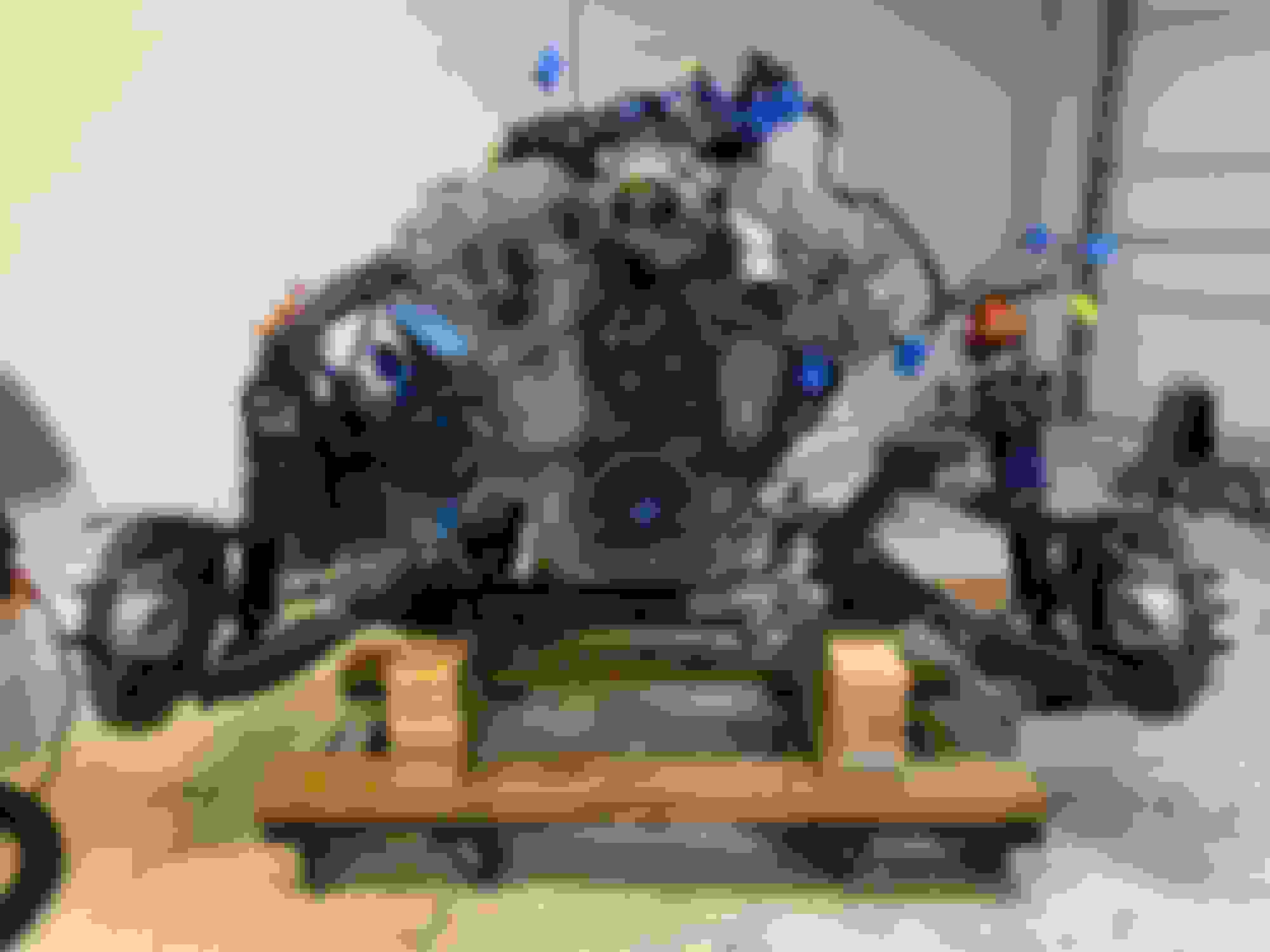
Wooden Dolly's: I think I ended up buying 6 of these from Harbor Freight. They're like 8 bucks a piece on sale, so not a huge investment, but if you are short on garage space like me, these are huge. I originally used them for rolling around / storing both engines & both transmissions. I also used them for the rear subframe while I was building it up as one complete system to install back in the car (and roll back under the car when I wasn't working on it.) And I used them for the front subframe cradle so I could install everything as one piece from under the car. (This was totally ripped off from Gooflophaze and his LFX build & I'd advise anyone else doing this to do the same...it worked great...more on this below.)
Front Subframe Cradle: Again, this was totally's Gooflophaze's idea, I just ripped it off. (THANK YOU Gooflophaze!) This allows you to basically put everything together on the front subframe, lift up the car and roll the tranny / engine underneath and then set the car back down on to the subframe. Building it 13" off the ground was the magical height that allowed me to basically just lower the car onto the dolly and bolt the subframe in all. Gooflophaze had an issue with his setup having too much weight in the front causing the engine to want to tip & said he would build his with a extra dolly upfront, I didn't have that issue, but as you can see in the first picture, I placed my dollies more up front verses in the middle because of the info he shared. FYI..I thought I was being clever and originally attached a 3rd dolly to this cradle further back for the transmission, but that keeps you from getting a jack under the transmission when it comes time to bolt it to the engine, so best to leave the tranny dolly unattached to the cradle and just pay attention to it when rolling around incase it starts to slide out from underneath.
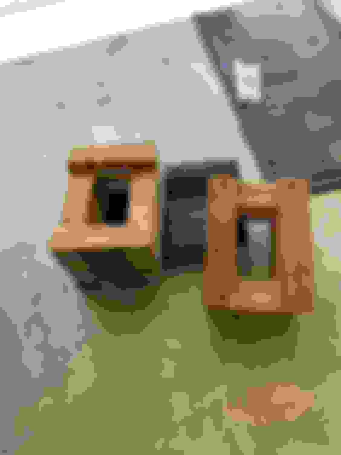
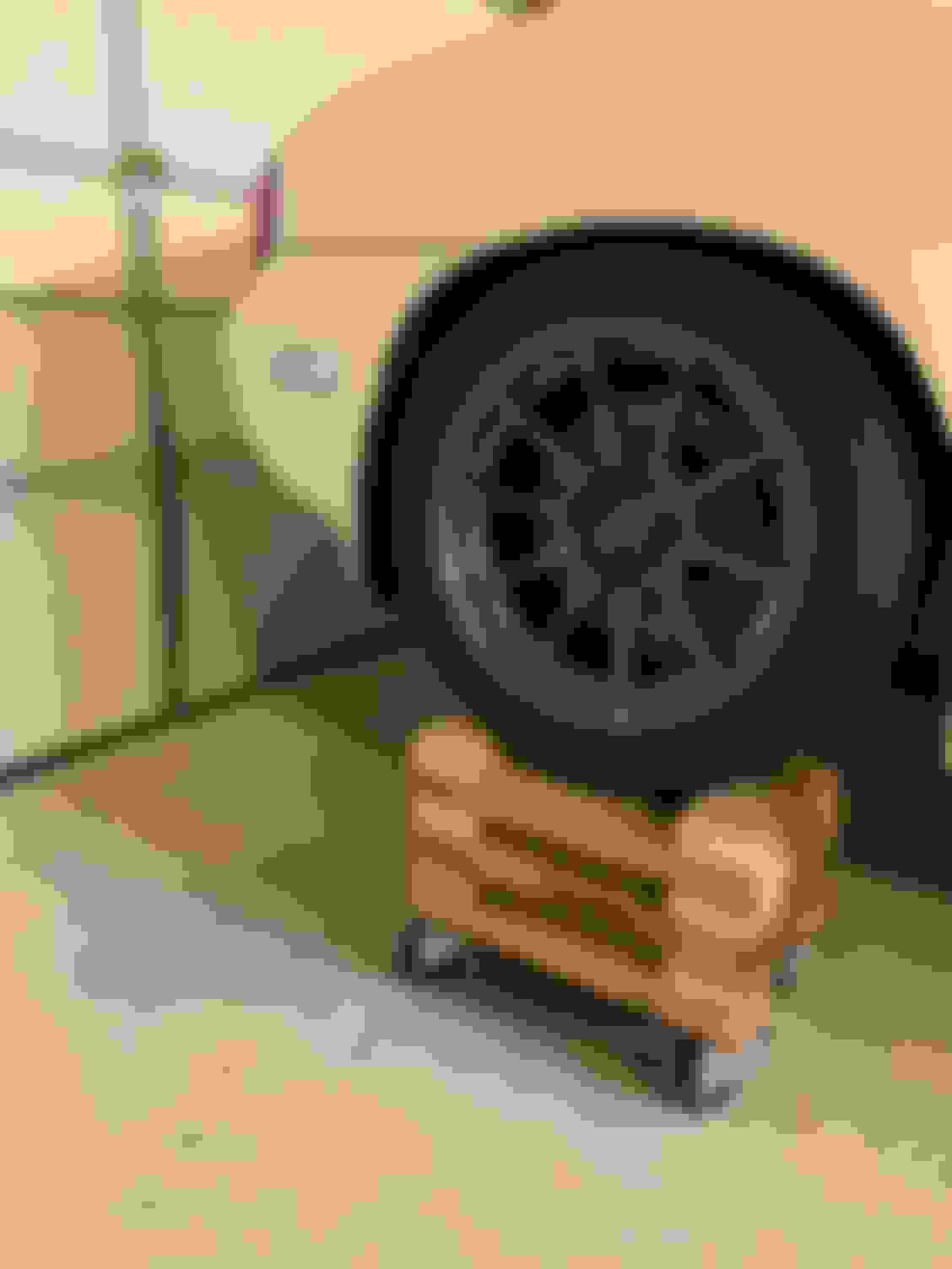
Roller Skates / Vehicle Dolly Lifts: If you couldn't tell already, I like to be able to roll things around. I bought these roller skates years ago when building a different car. I wanted the car higher to work underneath, while still on the dollies and not be sketchy, so I built these box cribs out of scrap 2x4's. Because the dolly's have bolts sticking out the top, I drilled holes in the bottom of the box cribs, and the bolts help hold them in place. This has worked great, and the car is super stable and safe to get under and still roll around with no issues. Since I'm about to build the exhaust (I so wish I owned a lift!) I may build these up 2 boards higher.
Currently, I'm using just the two rear dollies and the front subframe cradle to roll the car around. The front subframe cradle / HF wooden dollies are a bit hard to roll due to the weight on them now, compared to the rear ones, which are built to handle the weight better. I may build two more box cribs for my front dollies so the car rolls much easier, but for now, the car can be rolled around, is very stable and pretty much level, so no real reason to mess with it.
The fuel system work started in January when I removed everything, made a huge mess pumping the gas out of the tank, and upgraded the fuel pump. After that, I didn't touch anything until August of this year...So pictures are from two different time periods.
The LFX (or an LS swap) requires a higher output fuel pump, a corvette fuel regulator / filter (it's all one piece), and a larger fuel line (3/8 vs 5/16 on the stock miata.)
I started with the fuel pump. Pulling the fuel pump is pretty easy when you don't have the convertible top on the car any longer. Remove the cover, unhook the fuel lines and then there are eight screws and the whole assembly comes out.
Bad picture of the original pump with regulator still attached.
I swapped in a Deatschwerks DW200 pump that's good for both E85 or gas. (The LFX can run on E85) They have one that is basically made for the Miata and besides the wiring, it's plug and play. The wiring is pretty easy, they give you a pig tail with two wires, that you need to splice into the existing wires from the old pump. But the whole thing went together very easily. While you are swapping out the pump, if you have a 99 or greater Miata, you will also need to remove the regulator since we will be using the corvette regulator / filter. The regulator is super easy to remove, it hangs off on the one end. It's just two bolts and you can leave everything else as is & it's ready to put back into the tank.
(Sorry, I didn't take a photo of any of this...just the finished product.)
I was really hoping to run the new fuel lines without pulling the gas tank, but I ran into issues trying and pulling the tank (once the gas is out of it) is relatively simple (just 4 hoses & 4 bolts) and it's not that heavy. To get the gas out, I purchased this cheap $10 harbor freight fuel pump that uses batteries. I didn't expect much, but it really pumped the gas out quickly. The problem I had was that the little clip that holds the cheap hose on the pump let go & gas went EVERYWHERE. But what does one expect from a $10 harbor freight fuel pump?
Once the tank is out, you can easily get all of the EVAP & hose "stuff" out of the way, because it's all tucked up in there held with clips that you can't reach otherwise.
Most people install the corvette fuel filter / regulator under the car right around where the stock fuel filter on the Miata was originally installed. Its not the most friendly of spots, but I ended up installing mine there as well. I saw where a guy who did an LS swap had placed the Vette filter / regulator on top of the fuel tank. (sorry, can't remember the guys name to give proper credit). I couldn't get it to work with the AN fittings on the PTFE hose, but if you use hard line, like he did the AN fittings are smaller and it all fits. It's a much cleaner install, but I also wondered how hard it would be to swap out if you had a roll cage or roll bar installed.
To install the Vette filter / regulator where the stock Miata fuel filter use to live, you will need a way to mount it. I drilled a hole and installed a rivnut, which looks to be exactly how everyone else does it. It's pretty simple and works. I'm not crazy about the location, but it should work without any issues. I then cut some PTFE hose to length and added the AN connections for the top two hoses.
Here is a picture of the Rivnut after installed & the hose being marked for length.
Here's what it looks like all complete. (Actually, I need to raise it up to the second hole on the filter...that will get it a bit more tucked in there. I added the hole (where the bolt holding it is in the picture) for when I was trying to get it installed on top of the gas tank).
I haven't done it yet (because I wanted to wait until the engine was in the car to measure for hose length) but I'll run the fuel line down the inside of the frame rail and use some rubber lined clamps to hold it all into place sort of like this...
I'm going to run it on the outside of the front subframe when it goes up the firewall to keep it away from the exhaust pipe, as you can see here.
Then I'll connect the hose up here at the back of the engine where the high pressure fuel pump lives...
As far as the flex fuel sensor so I can run E85, I'm going to install that later, but haven't decided yet where I'm going to put it. Originally I was going to put it really close to the high pressure pump on the firewall, but that area is going to have the radiator surge tank, so not sure I will have the room there. I need to figure that out before I do all the wiring so I can prewire for it.
Flex fuel sensor on one end, and hard line to the HP fuel pump on the other. Fits nicely at the back of the engine as well and makes it easier to wire.
Originally, I started putting this into the fuel system post, but decided to break them up because they are so large. Also, nobody ever seems to discuss the EVAP system on any of these build threads that I read and this puzzled me a good bit to begin with, so hopefully this helps someone. I'm not an expert here, just did a lot of reading on the subject, so if something is wrong, please let me know so I can fix it for anyone reading in the future.
I didn't really understand what the EVAP system does & why it's there. So incase you are in the same boat, here's the simple gist...Gas tanks are a closed system that need to vent to keep the pressure inside the tank the same as the outside world, otherwise they either slowly implode on themselves, or bust open due to positive or negative pressure differences. Venting the tank is needed for the pressure to stay the same as the outside world. Adding air into the tank when fuel is removed to keep from imploding and removing gas fumes from the tank when the gas gets hot and expands in the tank to keep the tank from busting open.
The first direction, allowing air into the tank, is done by the gas cap. The gas cap will allow air to travel into the tank, but nothing to escape out of the tank. (That's why they check your gas cap when you get emissions testing done to make certain it doesn't allow anything to get out.)
The second direction, allowing gas fumes out of the tank, is the tricky part. Before emissions, cars use to vent to air (VTA) through the gas cap which was super simple. Modern cars, do not let these gas fumes VTA, but the tank needs to be able to release these fumes so it doesn't bust open from too much pressure. So, the EVAP system allows the tank to vent out the gas fumes, and sends those fumes into the intake so they can be burned while the engine is running making for cleaner air. Unfortunately, you can't just take a hose from the gas tank vent to the intake on a car and expect this to work. There has to be some middle men involved. Those middle men are a bunch of parts that basically lets the gas tank vent into a holding tank from time to time (This holding tank is a canister / box filled with charcoal) and when the engine is ready for those fumes, (i.e. engine running / hot enough etc.) other middle men pull those fumes from the charcoal canister / holding tank to burn them up.
Anyway...enough with my overly simplistic explanation of what the EVAP system does. Onto what I did to it to make it work for my swap. Because "Racecar", I went with simplicity and removed all of it. (The charcoal canister under the car, the valves & sensors & all the lines). Once all removed I was left with the rollover vent on the top of the tank & the two little fuel lines on the fuel neck to deal with. (and all the wiring harness BS...ugg)
Although the gas tank vent is on the top of the tank. You really want to get the fumes from the highest spot in the "gas tank" which for the Miata is the top of the fuel filler neck & thus why the NB Miata's look a bit odd and have the 4 fuel lines attached to neck. Those lines are the main filling hose (largest), the fuel filling vent (medium size hose), and the two EVAP lines (small ones). I'm fairly certain Mazda could have designed / packaged all of this much better, (i.e. one vent for both fuel filling & EVAP) but I think they were using what they already had (the NA Miata's don't use this same EVAP system) and made it work this way.
I attached a hose from the rollover vent to the bottom of one of the original hard lines that I had previously removed (Thus causing me to remove the gas tank and reinstall it again...) You can barely see the line tucked in the side in the picture below. I zip tied the rubber hose because it kept wanting to rub on items otherwise.
The hard line exits out into the trunk with the rest of the tank lines. I took a piece of hose and attached from there to the bottom of the two EVAP connections on the filler neck. For the top EVAP connection on the filler neck, I connected another rubber hose on it exiting out under the car on the drivers side where the power antenna use to exit. In case you are wondering...the stock Miata setup has this exit on the passenger side into a charcoal box for storage of the fumes, thus why you have the two hard lines, so one line can run back to the passenger side.
Sorry the picture is a bit busy, but I think you can follow the two lines...
I used this 90 degree fitting & hole left from the power antenna for the exit out the drivers side. Worked perfect!
I'm unsure if I'll get a lot of fumes with this method or not. I may add a small catch can that will VTA and fill it up with some charcoal and place that under the car if the fumes are too much. FYI...I stole this idea from Revlimiter. He did something similar to one of his cars and he seems happy with it.
Lastly, I need to remove or plug the EVAP Purge Solenoid Valve on the intake manifold of the LFX. This piece would be the part that allows the fumes to enter the intake.
Removing the purge valve leaves the following hole that needs to be blocked.
I was thinking about trying an EVAP block off plug for an LS engine. I can't find any specs on size, but it sure looks like it would work. Even has an offset for the bolt height being a tad lower. Has anyone tried this? They are cheap so I'll probably pick one up and just try it out.
If that doesn't work, I'll figure out some other way to close up this hole.
And that is all the EVAP changes. Once I figured out what I was trying to do, everything was pretty simple.
On the evap purge solenoid, the hole it leaves is a very awkward size and shape. I ended up just filling the evap solenoid tube with epoxy and then left it bolted to the manifold. Works just fine to keep the hole plugged.
That LS plug kit looks like it might work and would be cleaner. I'll check the evap solenoid part number and see if it interchanges with the LS engines.
Edit: The evap solenoid is specific to the LFX, so no idea if the LS cap will swap. I'll probably end up ordering one as well just to see.
It is a really odd shape. I had sort of the same idea with the epoxy if the LS block off plate doesn't work. I was considering just epoxying the intake manifold hole itself. The purge valve end would be easier & cheaper if I ever want to add the EVAP back.
I did a quick cross reference on the solenoids too, and they are different, I found a picture of the LS solenoid end on the internet...
Here's a picture of the LFX solenoid end...
They are close. Hard to tell with pictures, but It looks like ours might go into the manifold a little deeper, but that shouldn't be an issue with the block plate.
I'll order one up later tonight and let you know the results when it gets in. Happy New Year!
So I had to go to Summit Racing today to exchange a couple items and bought an EVAP delete plug while there. It's not perfect, but pretty close and will definitely work.
If I really cared, I could always grind down the offset, that would make it fit perfect, but it does seal as is.
I'm more OCD than I'm acting here. Its bugging me a bit that it's not ground down and painted black so it matches the intake better. My real OCD is the valve covers not being painted! BUT...I told myself a couple months ago that if something can be done after the car runs and doesn't require a ton of rework, it needs to be set on the back burner for now. Goal is to get the damn thing running!
I've also over restored a car before. It became no fun to drive because I was always worried about messing up the paint. (Or more specifically, other people tearing it up) This car will get driven hard and a little banged up just driving on the track and runs a high chance of getting seriously torn up (my two local tracks are unforgiving). I'd guess 1 car gets into a real accident each track day and a couple get into lesser accidents. I don't want to be worried about the "paint" and definitely don't want to won't be hard parking it.
That all said, not going for a half *** crap can car build either. I want it to look good and be done right / reliable. Fingers crossed I find the right "blend" between the two.
Nice progress - thought I'd throw this up this solution I used on my LS3 for the fuel filter after being dissatisfied with the "oem" filter mount - lesson learned on the LFX was that the passenger corner gets real busy, easier to route fuel under the drivers side (and the LS allows you to flip the injector lines to the other side easily). https://aeromotiveinc.com/product/2-5-t-bolt-clamp/ - there are some ebay copies that are cheaper and I cant' remember the exact size I ordered, and I did make the filter thicker with some old silicone intercooler coupling to get a good grab. Steel plate with some M6 threads welded on, then welded that onto the body. Edit: should also mention this is v1 of this fuel line - the tubing was a little bit lower than the frame rail, I cut it a little shorter, reflared, and used a pre-made 12 inch AN hose with a 90 fitting. It's nice and tucked up now.
Goof...Thanks for posting up that clamp. With the two bolts, I can see how it allows you to use that angle which tucks the fuel line up there even better. The single bolt hole on the "stock" Vette filter sort of keeps you from getting the perfect angle. The fuel line you bent up looks great & tucked up there already, but I can see how a 90 would work a bit better, but still what you have v1 looks great. I really like that you ran hardline too.
Since my earlier post, I stuck mine up a little higher using the original bolt hole on the filter. Its better, and pretty protected now, but I wish it was a little better protected by either the rear subframe brace or the frame rails then it is.
Its funny you mention how the passenger corner gets all filled up. I don't have heater hoses or AC hoses and that area is still tight. I put the wiring harness back on the car to check fitment for where to install the O2 bung and where to install the bung on the coolant tube. It's tight, I didn't get the wires that go back to the transmission ran correctly. I think I'm going to have to remove the coolant tube to get the wire harness back there. I really like the idea of running the fuel line on the drivers side. If the LS sit's like the LFX you have a little extra room on that side too. I noticed the engine is offset a little bit to the passenger side to make room for the steering.
Is this a new LS build? or an older picture from the last one you built?
I should probably do another round of updates - the LS3 and LFX builds kinda merged more towards the end of the LFX thread, as I tried to apply lessons learned on the LFX into the LS and show those off - and, subsequently, I've made improvements on the LFX backported from the LS - just recently, redid the fuse box mounting and fuse box type, and I should probably document "Adventures in learning how to fabricate Air Conditioning Lines" at some point. There is a real short LS3 thread I made here but it wasn't really breaking any new ground.
No new projects underway at the moment, but there is an RX8 sitting in the corner that needs a new powerplant...
Very much appreciate your build thread. I've read it countless times and it's helped me tremendously with mine. And will even more so here soon, since I'm about to start all the wiring!
That RX8 will be a cool build. I was looking at the Keisler Automation RX8 kits the other day and it made me think that I should have looked at the RX8 radiator for my build. Quick look at size makes me think it would basically drop in, and I believe it uses the same NB radiator "posts" to hold it at the bottom. The in / out looks to be easier to deal with & no radiator fill / neck. I'm working on / almost done with all the coolant stuff now and if I hadn't already decided upon / bought a radiator I might have bought an RX8 one to try. Only item I have left as an unknown is the radiator fill neck / overflow tube. I'm thinking the best answer is to cut off the neck & find someone who can weld up aluminum, since I don't have that ability, but how did you handle all of this?
1. Have the radiator cap at a higher pressure than the purge tank cap, so theoretically, it never opens. Then just in case it does, have the radiator overflow tee into the steam vent line and allow the surge tank to take any overflow from radiator / have the surge tank dump into an overflow bottle? (This is the method I was thinking about doing..)
2. Run the exact same radiator cap (say 18 lbs) on the radiator and the surge tank, have both overflow into the same bottle with the radiator able to pull back in fluid? (or same version of this, but with radiator at higher pressure cap than surge tank?)
Sorry, sort of jumped on a huge tangent when you mentioned the RX8 and I have been thinking about all of this lately.
I'm interested in your RX8 build when you decided upon what you want. If sticking with a Chevy, may I put in a vote for an LF4. I have a buddy with an ATS-V that's 550hp at the wheels with basically just a tune. It's stupid fast.
I respect the goal of a lot of Keisler parts - they look really nice, well engineered, buuut I kinda want to flex my new fabrication skills and see just how much I can make on my own / how badly I can **** off the RX8 purists (holy crap, they're borderline toxic). I've even gone so far as to seeing if I can adapt caddy SRX axles to RX8 outers with just a spline cut and save costs, instead of having new parts made. And my dad mistakenly bought a "spare" getrag diff off ebay, but it's from the year after the ones we use on ours, so the case is different - and it sat in a box in a corner for 6 months before we opened it, so no chance on returning. The RX8 goal, though, is mostly to have a daily driver. My LS is "too nice" and I can't actually enjoy it for fear of getting top slashed or stolen or dinged or... if I were to actually take it anywhere (pre-covid). So I'm actually considering an automatic transmission.. I know, not sexy. I flirted with the idea of going older, like maybe the "Merican Barra" Vortec 4200 since they're cheap, non-direct-injected, could be megasquirted, and apparently take to boost well, but ultimately too tall for the engine bay.
I haven't actually torn into the RX8 yet, it's just been sitting, so I can't say I'm familiar with all the dimensions yet with regards to radiator. On the LS I used https://www.summitracing.com/parts/hre-34327rnf , which just barely fits between the frame rails, has the inputs/outputs on the correct side, but it is an SBC port size that I had to adapt with TIG to more easily mate up with the LS - and while I was at it, I altered the angles to make it a little easier for hose routing.
As far as pressures go - I was looking into modifying a radiator cap for the LFX by welding or some other aftermarket method, but ultimately, I just closed off the overflow port with a silicone cap. Functionally the cap doesn't do anything at that point, it's just a plug. If I had to do it over again, I'd weld a cap over the neck with TIG, but functionally the sealed port does the same thing - and now that the radiator has some miles on it, I don't think I'll bother welding dirty aluminum unless there was some major reason to. Could also retap and put in a bolt in place of the port, but unless the silicone fails, the only reason to change it would be aesthetics. And I can't remember if I made that update in my thread or just mentioned it in Passey's - but we ditched the Cadillac(?) plastic surge tank and went with an aluminum tank from summit. I'll post a picture in a little bit, just realized my phone was out of juice.
I think this is the tank we used, can't find my summit receipt - https://www.summitracing.com/parts/ctr-80-202 - it's either that or the 1.25. Top elbow runs to the steam port. Had some hard starting issues that I attributed to the battery, and rewired the whole thing to the LS spec with the massive main relay, and ended up extending the power wires off the GM harness another 12 inches or so to mount the new bussed fuse box - fuse box is mounted on 3 corners so it's not going to wobble and spark. Still need to put split loom over the wires and tidy up / make a new alternator wire. Also.. it turns out the hard start turned out to be that inline AN fuel filter, it was clogged (argh!). So that's kinda suspect now, because the tank was corroding and has been cleaned, the wix filter in the FPR should be doing 10 micron (supposedly), and this AN should also be 10 micron. Confounding.


 0
0