When you click on links to various merchants on this site and make a purchase, this can result in this site earning a commission. Affiliate programs and affiliations include, but are not limited to, the eBay Partner Network.
I really didn't get much done this weekend with high hopes of having everything under the car done & no longer needing to crawl under it. Unfortunately, it's that time of year where all the plants are having a wild orgy, the air is thick with plant sperm, and bubble boy's allergies are in hyperdrive. Needless to say, I felt like crap and got little done. I did spend a couple hours down in the garage, and I spent some time ordering a few parts / did some research, so something got done, even if it doesn't show.
Anyway...with the coolant tube in place & the radiator moved to it's new home, it was time to find / fit coolant hoses. FYI...All of this reads like I did things exactly in this order when in truth I was doing these things at the same time and trying to figure out fitment of each item. (Thus why the radiator bottom was moved, and a month later I moved the top of the radiator out when I realized I needed more space still.)
Water Pump Outlet
A lot of guys....(actually, I think every build thread but Passey's) modify the water pump outlet to give more space for the upper radiator hose. Some people just shorten it, but most also add a 90 turn. It's cast aluminum and since I still need training wheels for my MIG welding...this wasn't gonna happen...So my goal was to not mess with it. Thus the reason for moving the radiator the little bit that I did, and the fan over to the passenger side. I have enough room & did not need to modify it. (Small win!) FYI...anyone doing this in the future, who are also lacking skillz, I noticed (after getting my stuff all done) that Keisler Automation makes these pipes with a 90 for the RX8 swap, so you can probably buy it from him if you also can't melt aluminum.
Here's the stock one unmodified.
Here's a picture of LukeG's Exocet that I stole from his build thread. You can easily see with the intake off, the 90 bend and tube he put on his at the very front of the engine.
Upper Radiator Hose
Laugh all you want (I'm gonna cry personally), but I have 8+ hours into this damn hose. I really don't like the idea of adding points of failure with a splice and I'm convinced there is a rubber hose that will work. I'm also convinced that hose does not exist at any of the 8 different auto part stores around me. (Yes, I even visited a couple more than once with my little bent coat hangers trying to find the unicorn of coolant hoses.) NOTE: Although I told the guy behind the counter that I was swapping a Chevy engine in a Miata, I had 2 of them insist they needed to know the year to look up the car and find the hose. SMH
Bent some coat hangers to get the shape of hose I needed & then went looking.
I even came close once...(and this hose doesn't even need a reducer, it's 1.5 at the water pump outlet and 1.25 at the radiator...almost hose nirvana!)
In the end, after it was obvious I was wearing out my welcome at all the auto-part stores, I bought two hoses and a coupler/reducer.
(Part# incase anyone or my future self need them)
1.5 hose = 60910
1.25 hose = 61452
So I wouldn't have to look at my defeat, I spliced it under the intake, hiding it from my eye.
Lower Hose
I found this hose at the first store I went into...5 minutes into my search. I think finding it so early on, only drove me to keep looking more for that upper hose. It's stretch just a little bit, but should work perfect.
Part # = 62452
It's mainly hidden by the big boy sway bar, but you can see she fits nicely.
Expansion Tank & Steam Vent
If you aren't a Chevy guy, or old school, (both of which described me before this project) you're probably asking, "What's a steam vent?" and think an Expansion Tank is the same thing as a Coolant Recovery Tank (hint: It's not). Let's start with the steam vent. It's simple, it's an outlet (vent) at the highest point of the engine where any air bubble in the coolant can escape, so it's not trapped in the engine. (Remember air is lighter than water and travels to the highest point it can find to try and escape.) Traditionally, cars didn't have steam vents because the top of the radiator was the highest point in the cooling system, but in more modern cars (not just Chevy's), with lower hoods, the radiator ends up lower than the highest point on the engine, and the air bubbles have no way to escape / get trapped in the top of the block causing things to get hot pretty quickly.
Steam Vent on the LFX is on top of the water pump outlet. Some of the LS engines have 4 steam vents, one on each corner.
The Steam Vent will push coolant out of it along with the air bubbles, this is where the Expansion Tank comes into play. The expansion tank is pressurized like the rest of the coolant system (unlike a recovery tank that is not pressurized) and it's placed at highest point in the system. Thus the air bubbles (and fluid) will travel to the expansion tank. The expansion tank allows the steam to cool down and transform from its gas state back to fluid. With air being removed from the system, there is a need for more coolant to take up this space. This also comes from the expansion tank. The expansion tank dumps fluid back into the coolant system. Once the engine is filled with coolant / normally operating, the expansion tank is only half way filled with coolant, so there is room for steam to condense back into fluid and enough fluid in the tank that it can be added back to the coolant system, keeping everything at equilibrium. If for some reason the tank overfills / pressure does get too great, the expansion tank has a "radiator cap" on it that allows fluid / pressure to be relieved from the system just like a normal radiator does into a recovery tank or if really old school onto the ground.
Here's the tank I used, with the top elbow receiving the "steam" and the bottom elbow adding coolant back into the system (remember the hose barb that was added to the coolant tube in the last wright up...it connects there)
FYI...Top elbow is 5/16" just like the steam port on the engine. Bottom elbow is 3/8", 1/2" would have been easier to source and work just as well.
I needed a way to support the tank. I thought about installing it on the firewall at the back of the engine bay, but that area is a bit tight & everything gets connected back there, so I repurposed the bracket that was used for the washer fluid before. I added a piece of metal on it & welded some nuts on the back so I could easy screw on the tank.
I actually used one of the nuts on the bracket, so I only had to weld one nut on the back of this one. I haven't done that yet in this picture. Quick test fit before painting.
A hose connecting the steam port to the tank & a hose from the tank to the coolant tube. Add a few hose clamps to route the steam vent hose properly & Voila! Done!
This picture shows the hose attached to the steam port headed to the expansion tank.
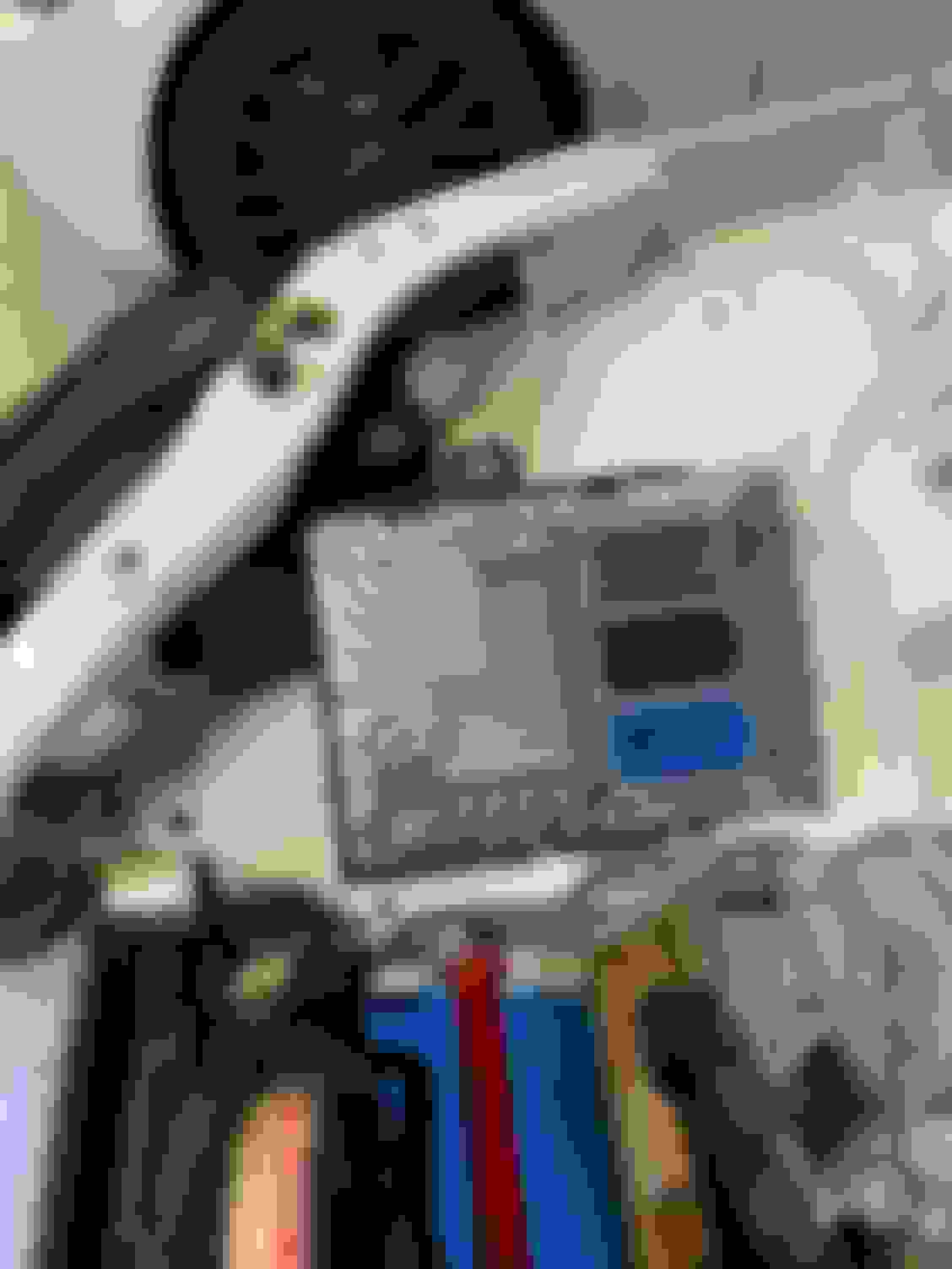
Ran the hose behind where the computer will live and up to the expansion tank.
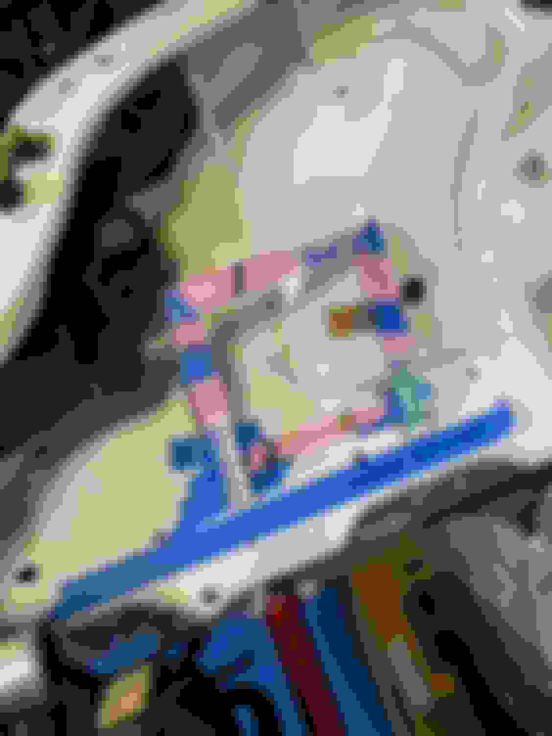
Here you can see the hose from the expansion tank that returns the coolant into the tube where we welded in the hose barb.
In the ideal world, I would have used a radiator that didn't have a fill tube / radiator cap, since this is all redundant with the expansion tank. Because I used a radiator with a cap, I needed a solution for the overflow. Some radiators, have this port taped and screwed in. On the SuperMiata radiator it's welded in place. Originally, I was going to run this into the expansion tank using a Tee into the steam vent line. I was speaking to Gooflophaze about this (found much earlier in this build thread) and he suggested I just cap it off. I didn't realize they made caps for this, but loved the idea and after a little shopping on amazon...I had a cap on it's way.
The cap blends in with the air intake behind it a little bit, but you can see it here. (This thing was thick and really needed for the radiator cap to be trimmed down if you were going to open the radiator cap regularly.)
The only item left in the cooling is running the overflow tube from the expansion tank. Once everything is filled correctly, it shouldn't burp any fluid. I'll add a small catch can behind the tank. I just need to find one first, and I haven't looked for one yet. For now, I can just run a tube down to the ground and let it overflow that way. (I plan on running distilled water since track car.)
That covers all the coolant work / changes. It doesn't look like much in these write ups, but it required a lot more time than I would have originally guessed.
Looking good! Make sure you get a raised bead on each side of the upper coolant hose coupler for the clamps to butt up against and seal. I'd be very wary of it without them as it will almost surely leak. Any local hot rod shop can do it for you quickly and cheaply. Or you can diy a pair of pliers to do it yourself.
Looking good! Make sure you get a raised bead on each side of the upper coolant hose coupler for the clamps to butt up against and seal. I'd be very wary of it without them as it will almost surely leak. Any local hot rod shop can do it for you quickly and cheaply. Or you can diy a pair of pliers to do it yourself.
Thanks! I used this guy as the coupler...I don't think it will leak. Or am I missing what you are telling me?
Here are the three hoses that we grabbed from the local auto zone. Two of them worked well for the upper and lower hoses with a bit of trimming
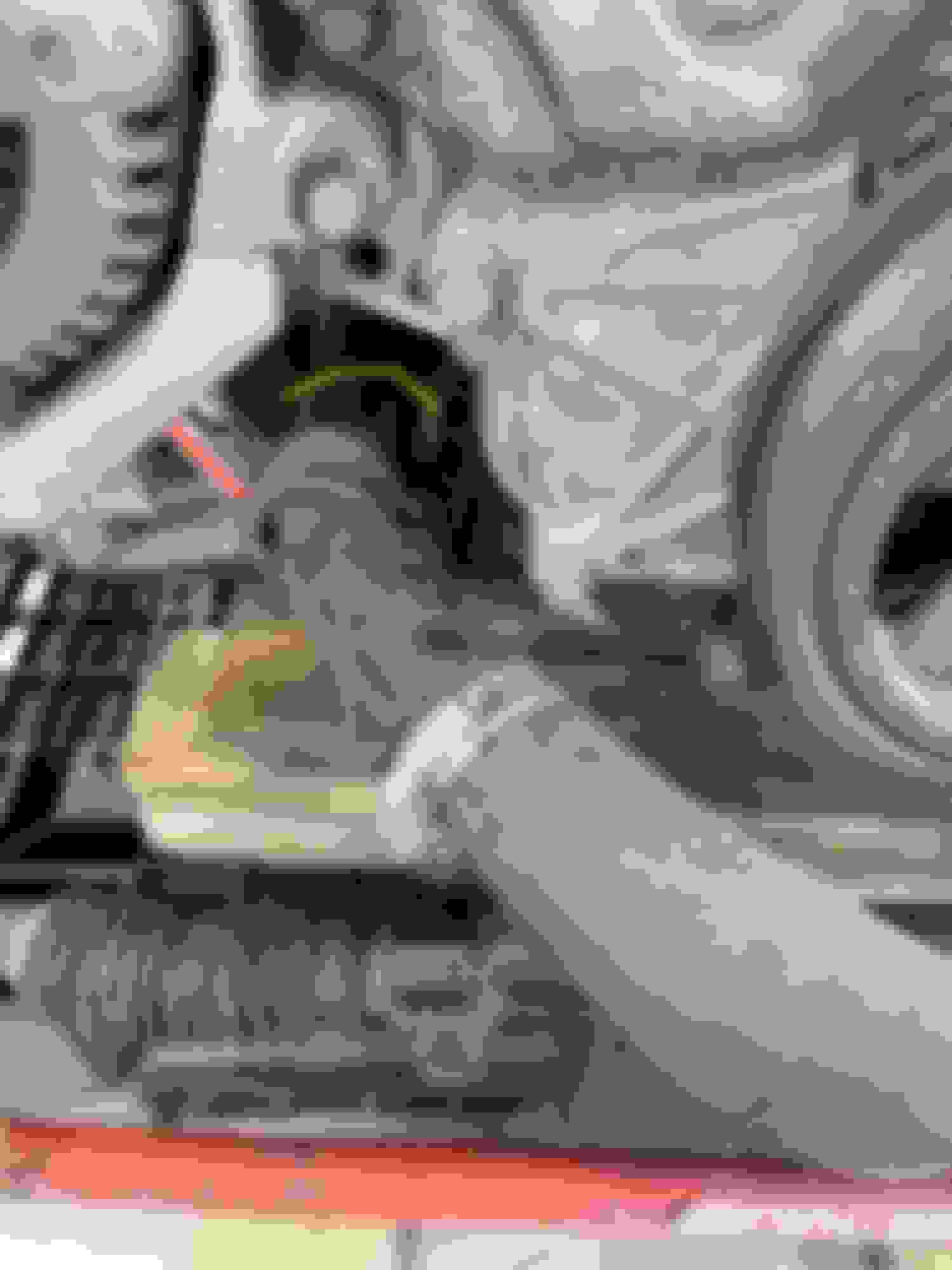
Here is what we did to the lower cts pipe. We just cut it where the yellow line is and removed about 2� and clocked the outlet so that it didn�t hit the sway bar. Also notice how we attached the bracket there at the front.
Hey, thanks for the info! These build threads are really the only directions on how to do this for people who are new to fab & engine swaps (i.e. ME) Cutting that pipe and rotating it like that is a great idea. It never occurred to me to cut the pipe in two / remove a chunk and then weld it back. I really like that solution. I also used the same spot on the alternator bracket to attach mine, but mine sticks out a little lower than yours does (still high enough to not be an issue.)
FYI, Just a follow up on what we found in our transmission that locked itself in 4th gear. It turns out that the 5-6 shift selector fork has a lot of play in it. It is the only fork that is constructed of 2 pieces instead of a single forged piece. The two pieces are held together with a single roll pin that deflects pretty easily. This allows a lot of unwanted movement in the selector fork. We tig welded the fork to the shaft and then used some wicked bearing retainer to hold it in place. The difference was substantial once we reassembled the trans. We will see if it fixes the issue we experienced.
FYI, Just a follow up on what we found in our transmission that locked itself in 4th gear. It turns out that the 5-6 shift selector fork has a lot of play in it. It is the only fork that is constructed of 2 pieces instead of a single forged piece. The two pieces are held together with a single roll pin that deflects pretty easily. This allows a lot of unwanted movement in the selector fork. We tig welded the fork to the shaft and then used some wicked bearing retainer to hold it in place. The difference was substantial once we reassembled the trans. We will see if it fixes the issue we experienced.
If this works please offer this as a service!
PS- I emailed you in a chain with Keisler about a dry sump setup.
Love the knowledge share. For the trans dis/reassembly - was there anything more exotic than a split bearing puller and press? Or did you even need to go that deep for the shift forks?
Love the knowledge share. For the trans dis/reassembly - was there anything more exotic than a split bearing puller and press? Or did you even need to go that deep for the shift forks?
We took the whole thing apart. There is nothing really special needed except for a 27mm allen for th plug in the bellhousing. We didn't have one laying around so we just made one real quick. The trick to getting the gear stacks out is each one is held into place with a circlip at the bell housing. One is accessed from the bellhousing (behind the plug) and the other from inside the case. Both need to be done at once kind of. Two person job really.
This is great info all around. Thanks everyone for sharing!
I'm guessing there is nothing that stands out with the answer, but I'm curious why they made a shifting fork as two pieces vs just one? (Not sure I've ever seen that before, but then again, I have only seen a handful or two of transmissions pulled apart and most of those were from big diesel trucks 30 years ago.)
I don't understand what you did here..."We tig welded the fork to the shaft and then used some wicked bearing retainer to hold it in place". I get tig welding the two fork pieces onto the shaft , but I don't understand the "wicked bearing retainer" part. Anyone able to explain that part to me?
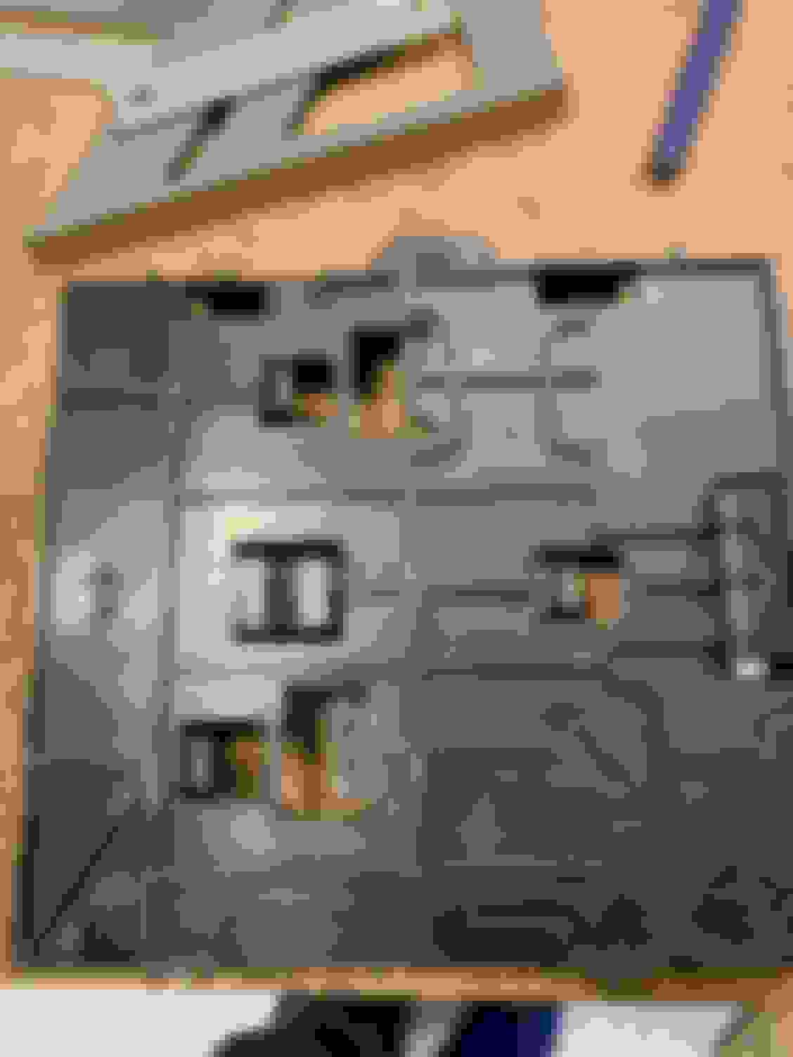
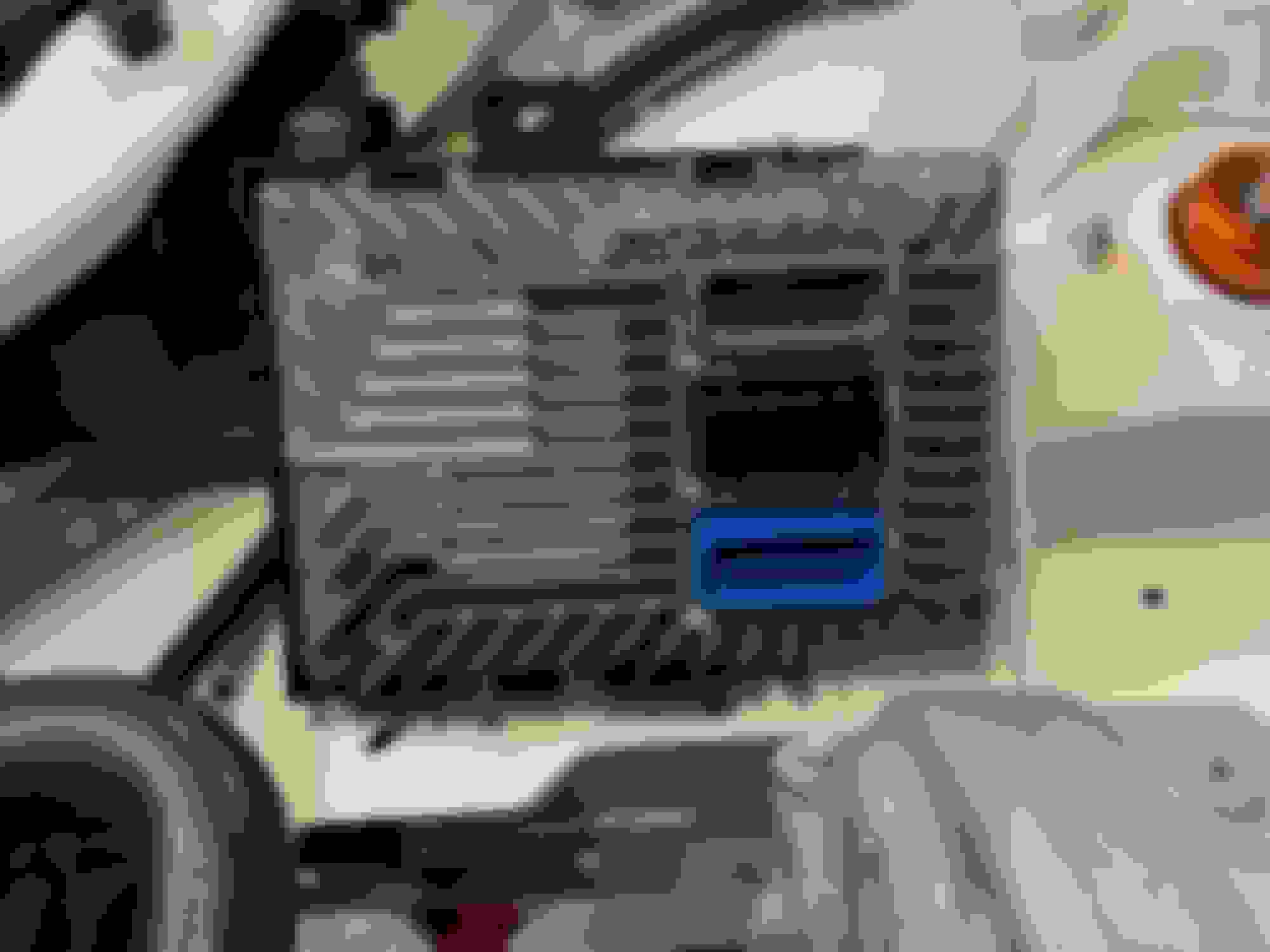
Sticking with my pattern of installing the items that can�t be moved to somewhere else easily, one of the next parts I put on the car is the ECU (engine control unit). Most of the people with an LFX swap (including myself) use the Chevy E39 ECU which pretty much must be installed in the front of the engine bay on the passenger side due to the wiring harness.
I�m sure you can move it, but that requires elongate over 200 wires. I�m obviously into masochism (who else does an engine swap?!?) but I�m not crazy. So, the Chevy computer needs to find a home in the front right of the engine bay. A spot where nothing is flat or easy to mount something too.
Unfortunately for me (and anyone else doing this) the ECU doesn�t have any holes or any easy way to attach it to anything. I checked out what others have done, and for the most part, people modified the plastic Chevy mount (Part # 22897960). I decided to do the same.
The Chevy mount also doesn�t have any good places to attach it to anything. It has some �clips� built into the backside that must hold it on the Camaro. The good news is that the plastic is pretty thick so drilling holes in it to mount it somewhere should work.
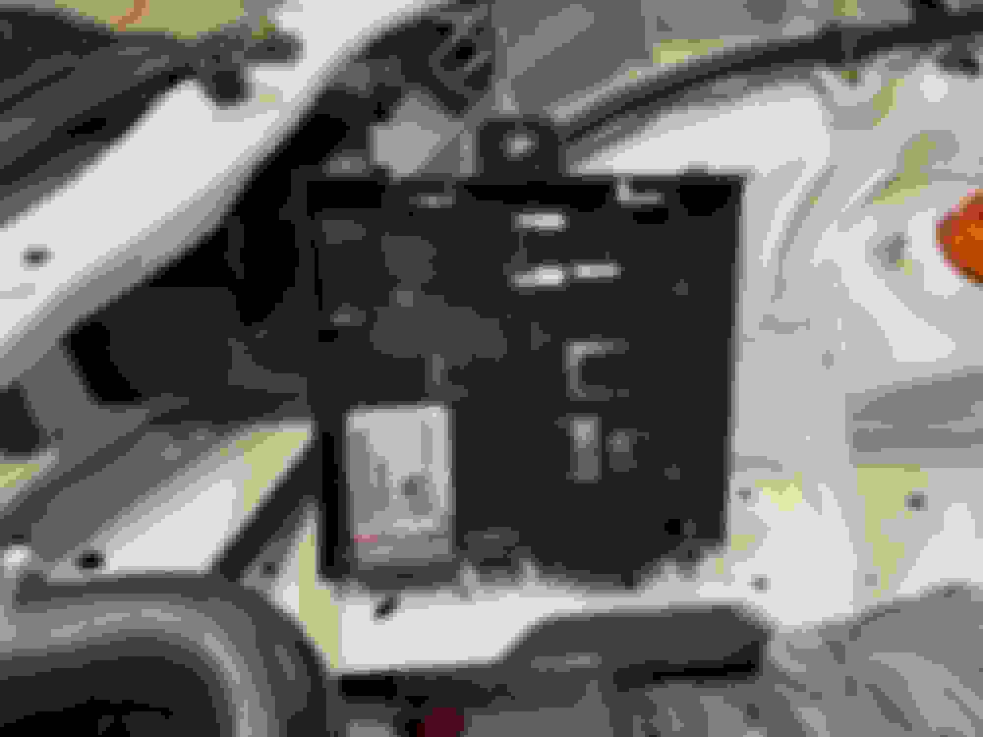
I really just wanted to lay the ECU flat, but after reinstalling the headlight, I realized I wasn�t going to have the room to do that. This looked like the best �spot� for it.
I have it leaning against the light & the little edge in this picture.
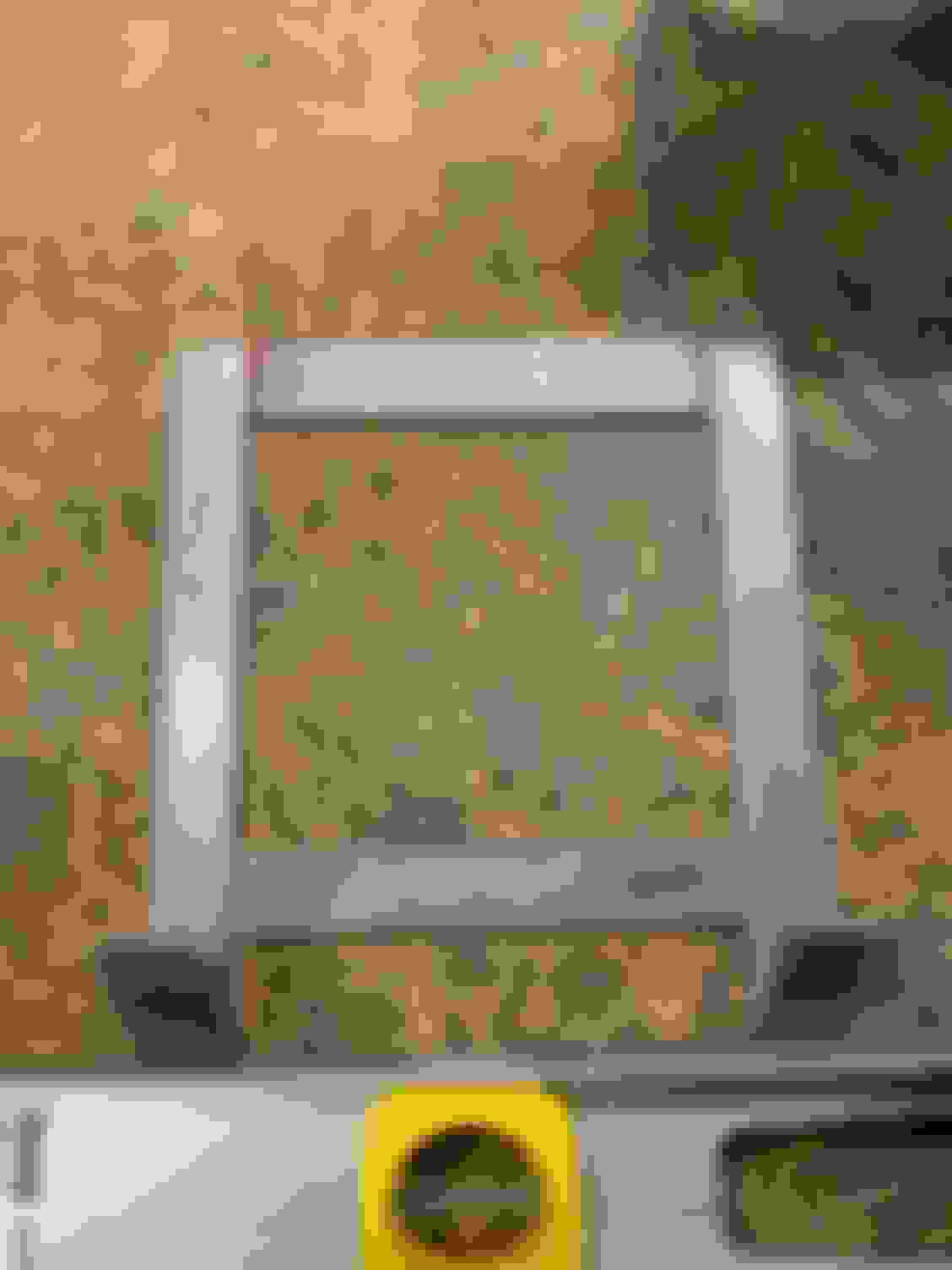
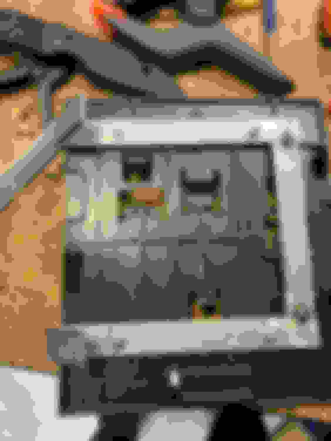
So, I needed to build a bracket to hold my mount. I rummaged through the recycling bin for some thin cardboard and went to town designing a bracket the old school way.
To make the bracket I sourced some 3/4� bar that was about 1/8� thick from my local HD Racing. I cut the 4 main pieces I needed using a band saw & on the long pieces where I needed to bend the �feet� I cut the metal about 50% of the way through which allowed me to easily bend them to the angle I needed.
I tack welded the top bar in place, and then figured out where I needed to drill the holes for the plastic mount to be attached to the bracket. I drilled out those holes on the bracket, but not the mount yet. Since the mount had those �clips� I had to cut them off first to make things flat.
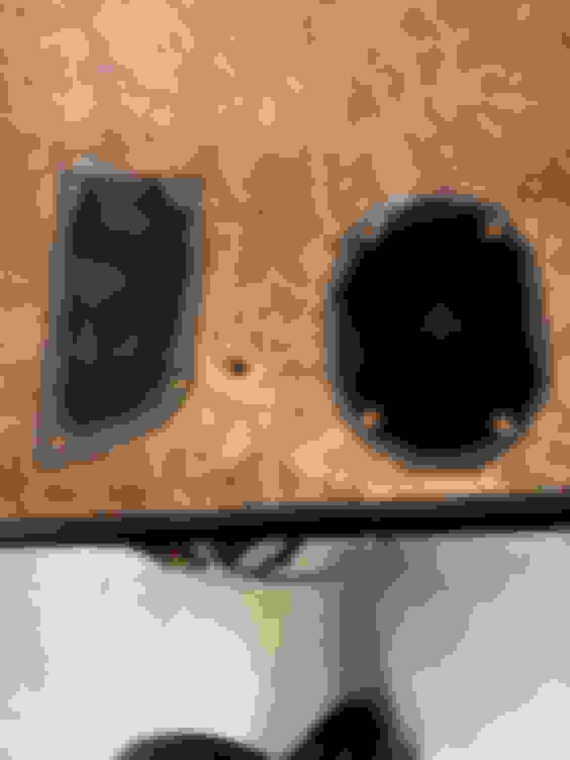
Here you can see the "clips" sticking up proud of the bracket
You can see where I cut them off here (all but the one, which wasn't in the way.)
From there I drilled my holes in the plastic mount (counter sinking them with some flush screws) and attached everything with nuts on the back of the bracket.
I welded those nuts in place, added the bottom bar that I had put holes in for mounting to the car itself and added a little support piece that connects to the stud on the side of the wheel housing that use to be used for the coolant water bottle. I also needed to add an extra piece of metal on one of the feet to keep things level, since the one side is sitting on a �hump�.
Back of the bracket all completed. You can see the extra piece of metal on the leg at the bottom right. Front of the bracket all completed.
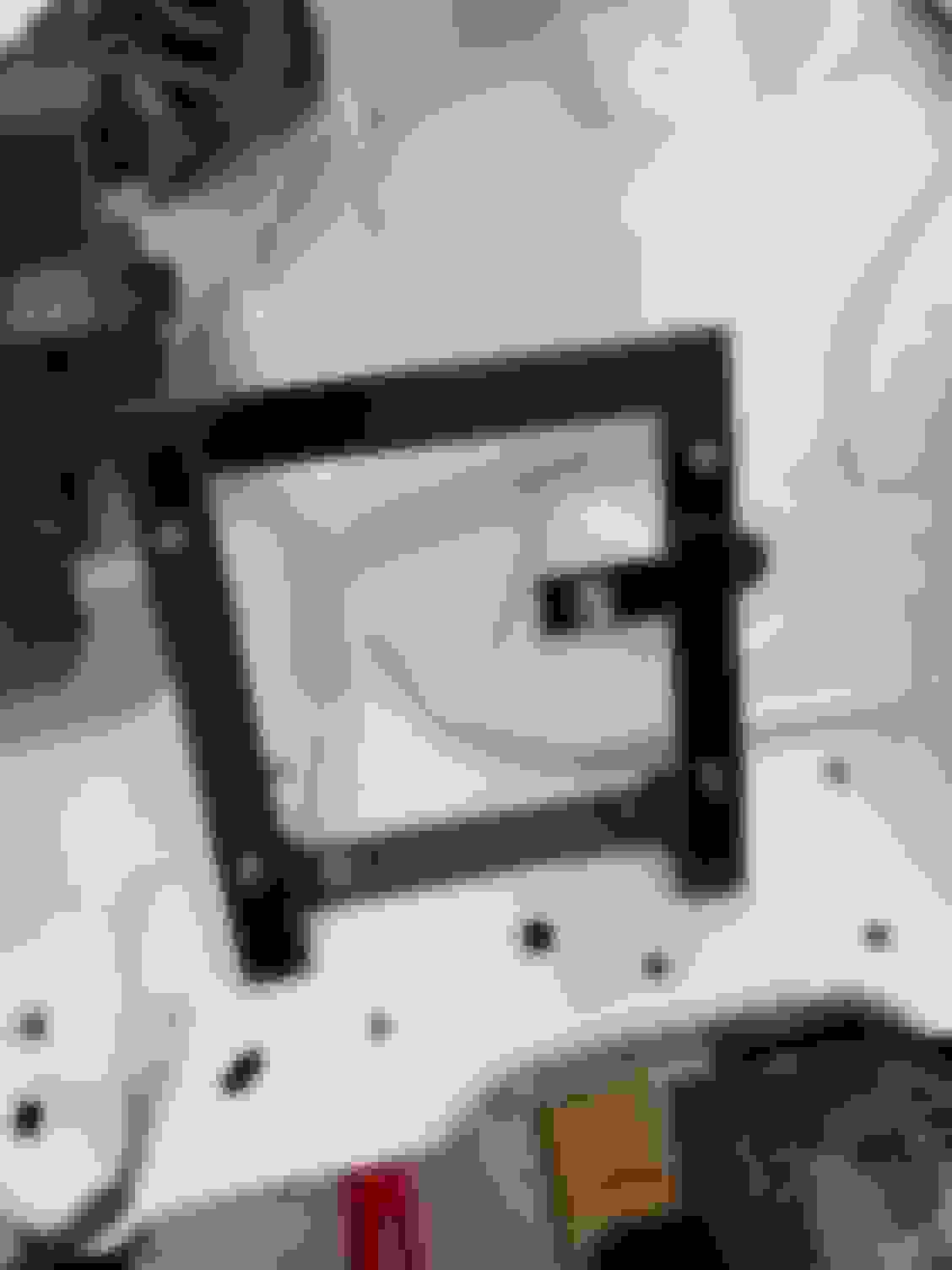
I installed it and figured out where I needed to drill some holes for rivnuts to hold the bottom of the bracket in place.
Ready to mark my holes for drilling out & installing rivnuts.
I didn't take a picture of me installing the rivnuts (I had one spin on me & spent forever getting that out before I had to redo it...) anyway, if you look at the left, you can see the two rivnuts with bolts sticking out. You can also easily see the "hump" that I was talking about earlier too.
A coat of paint to keep the rust at bay...and installed bracket / bracket & mount / & with ECU
So besides exhaust, this post should get me pretty close to all caught up (in the engine bay) as of last week. I'm leaving out the brake line changes I'm making, since I figured that would all go in one post.
This post reads more like a progress report / lots of pictures more than anything else. Most of this doesn't look like much, but its the little stuff that eats up time in your build.
Air Intake
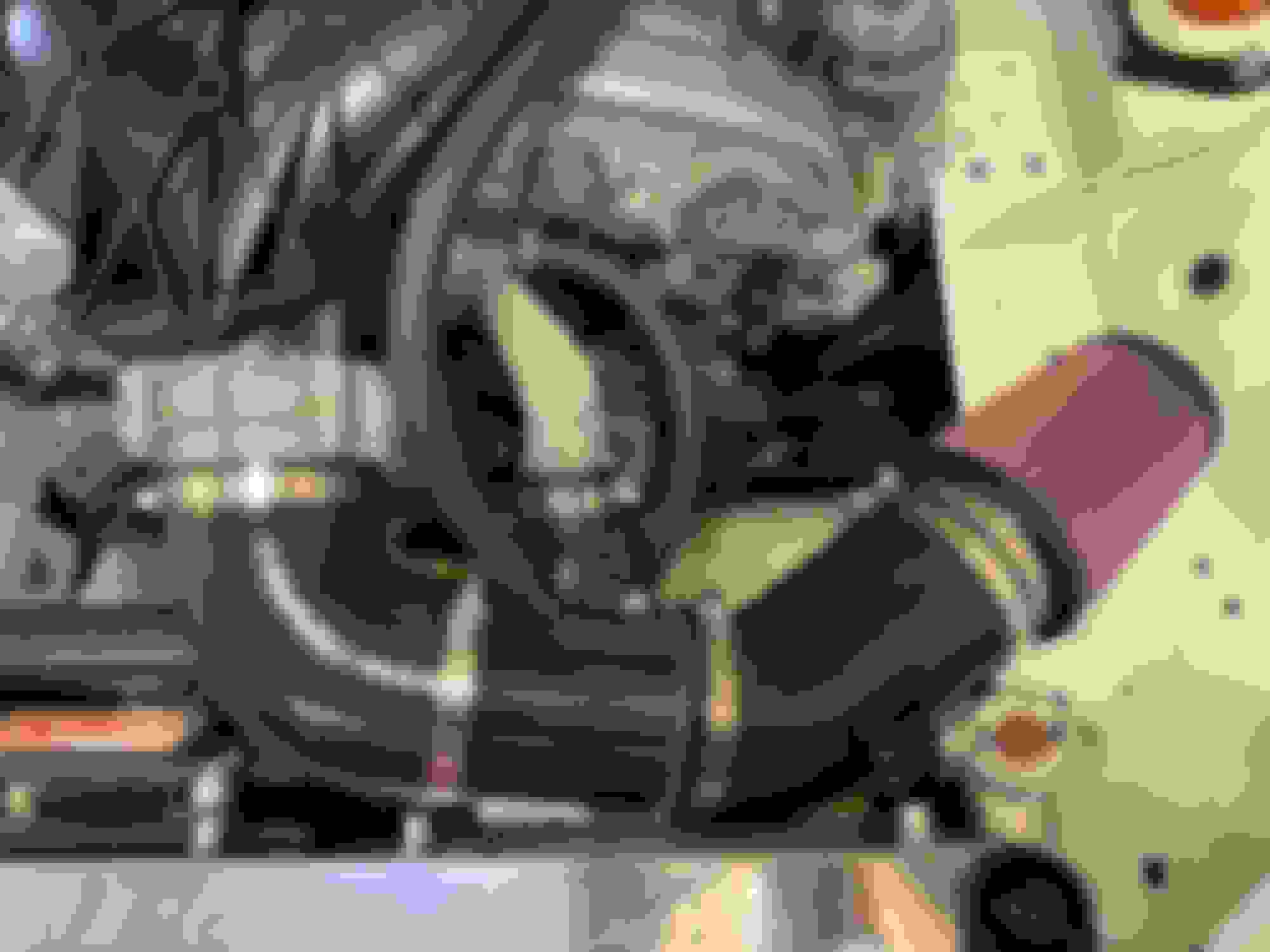
I wanted to put an Vette Snorkle on the car like the LS V8 guys do. (Yes, I know it's a bit tacky / black polyester corvette jacket wearing wanna be look to it, but I have no shame.) Anyway, I may still do this eventually, but simple is the answer here...and I called up Andrew @ Keisler and bought his setup since I couldn't find a 3" air intake tube that had a clean air connection and the Chevy MAF "bung" attached. (I don't have a TIG setup to fabricate one...leaving my other option to JB weld it and I didn't want to do that.) I ended up adding an additional 45 degree elbow (that I cut down on the one side) in the setup to keep the air filter from hitting the radiator fill neck and it also gets the filter out from directly behind the radiator. I would have preferred a larger air filter and ultimately install it in a "cooler" place, but this will work for now.
PVC / Clean Side Vent Hose
I really need to add a catch can, especially with this engine being direct injection & needing the valves cleaned already. But for now, I just put the stock PVC hose back on the engine to get thing running. For the Clean Side, the stock hose didn't fit right & is clunky, so I just used a piece of heater hose instead, and zip tied it to the intake manifold so its "out of the way".
Original "Clean Side" hose...I have no idea about the "bulge" and why it's there / what's in there.
Both hoses installed on the engine.
First Start
I already wrote about this out of turn. You can find more info about this back at post 60 something, but to put things in the correct time order/show when I did this work it goes here...FYI...this was mid January, I put oil in the engine & started the car for 1 whole minute! (no coolant) Was super excited about this! I spent a couple days getting up to this point creating a "junk" wiring harness. It was a good proof of concept on how I needed to wire things up. Here is a very quick clip of the engine running.
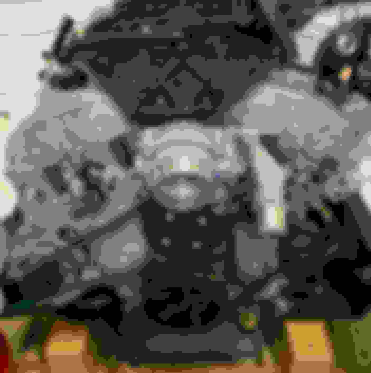
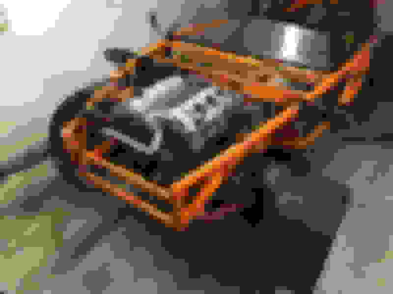
Harmonic Balancer
We had a couple warm days in early Feb and I painted all of the brackets & mounts that I wrote about already at that time. The rusty harmonic balancer has bugged me since day 1 and there never was going to be a better time with the radiator out of the car and a can of spray paint already in hand...So
Note: You all probably think I love High Gloss paint. I would have used a Semi-Gloss on about everything, but I had a can of High Gloss Black handy in the garage, and I didn't want to run to the store. This doesn't catch your eye as much in real life.
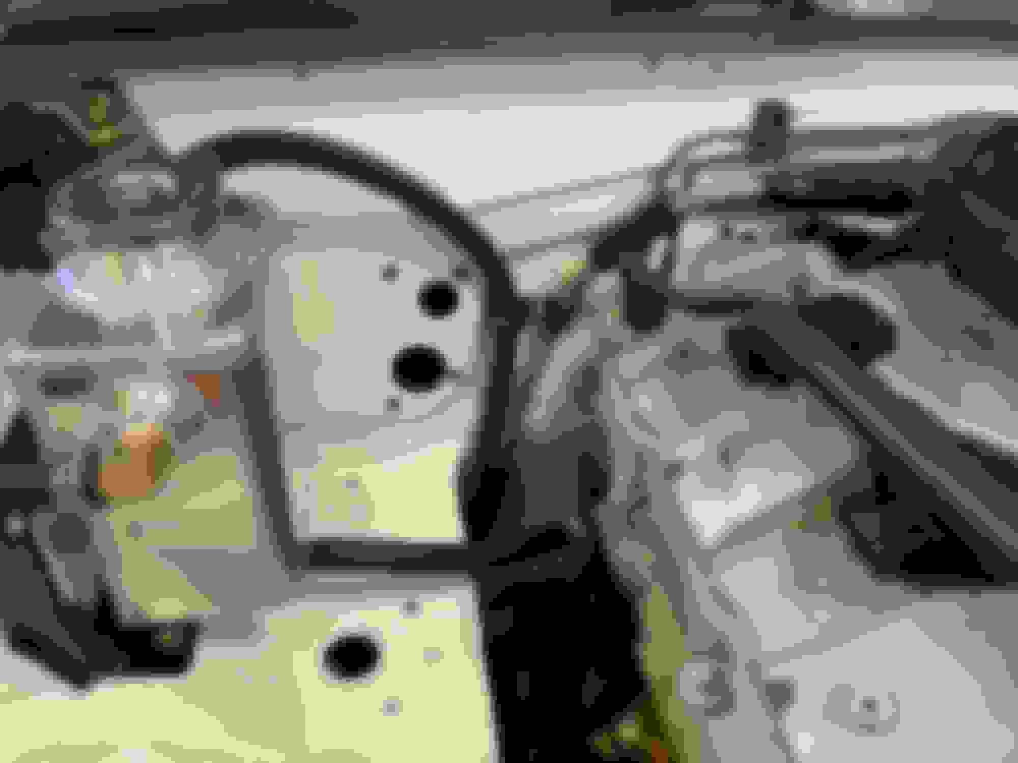
Firewall Holes
I had left a couple holes in the firewall that I should have blocked off before painting the engine bay. Ideally, I would have welded metal here before I painted. My first idea was to rivet some pieces of metal in place. Unfortunately, I wasn't going to get the rivets in from the engine side without removing the engine...and I didn't want the blind side of the rivets poking out into the engine bay since it's tight enough in this area. So, I settled on some button head screws and just drilled holes in the firewall to screwed a couple pieces of metal over these big holes.
I stuck a little RTV on these before installing so they wouldn't rattle. You know...because I'm really going to be paying attention to that on the track. SMH
Covered up the AC holes...and you can see the one drip I had when I painted the entire engine bay.
Back here was a pita. Looks like plenty of room from some views, but NOPE.
Fuel Line & Overflow Tube
I installed an overflow tube that for now is just draining under the car. I'll probably add a catch can between the expansion tank & the overflow tube, but for now, this will work. I attached both to the firewall and added some rubber hose protection on the fuel line where it wanted to saw off the paint & any other things it was touching already. I'm thinking I might make a heat shield for this little corner to keep heat off these & the brake line. That's something I probably need to do before tracking the car, but for the road I think I'm fine. These lines are 4 inches away at their closest point to the downpipe.
Overflow tube & fuel line both heading under the car.
I tucked both lines down behind the brake line...and wrapped the fuel line with some rubber hose anywhere it was rubbing.
Clutch Line
This line which came from the V8R kit needs to be 2-3" longer. It would allow you to attach it to the firewall and keep it out of the way better. Instead it's sort of stretched in a direct path to the clutch cylinder looking like the kid wearing highwater (aka Flood) pants in middle school.
Sorry, bad picture, but you can still semi see that it's pulled taut.
I put some rubber hose sleeves over the areas it's going to rub and mounted it as out of the way as I could. I wish I could have mounted it to the firewall and ran it under the brake booster.
So, what's left for the engine bay before we are drive this thing...(not counting the electrical, it's only a day or two's worth of work left!)
1. Exhaust needs to be cleaned up & install the header wrap (will do a post on that soon)
2. Brake lines need to be all hooked up & brake & clutch cylinders need to be filled / bench bleed.
3. Need to add Coolant (actually distilled water)
4. Electrical needs to be completed
5. Tighten a few things still (harmonic balancer bolt is the main one...it's just torqued to 70 ft lbs right now, it needs to be stretched X degrees more.
6. Body work (hood cut) and reinstalled with bumper & fenders
Just noticed - looks like you have a bulk hose running to the brake booster. OEM has a 1-way valve built into the hose so the booster have a reservoir of vacuum. Dunno how important it is, but instead of testing it, we adapted the OEM hose with a coupler.
Thanks for the heads up! I didn’t realize I needed one until recently. I just installed one over the weekend when I started working on the brake lines (and immediately stopped after breaking my cheap flaring tool). Funny enough the stock line that was on the car didn’t have the check valve in the tube, because I was going to reuse it like you did...so I bought an ATE brake check valve that’s OEM for some Chevys (gotta keep it in the family...lol) and installed it inline.


 0
0