When you click on links to various merchants on this site and make a purchase, this can result in this site earning a commission. Affiliate programs and affiliations include, but are not limited to, the eBay Partner Network.
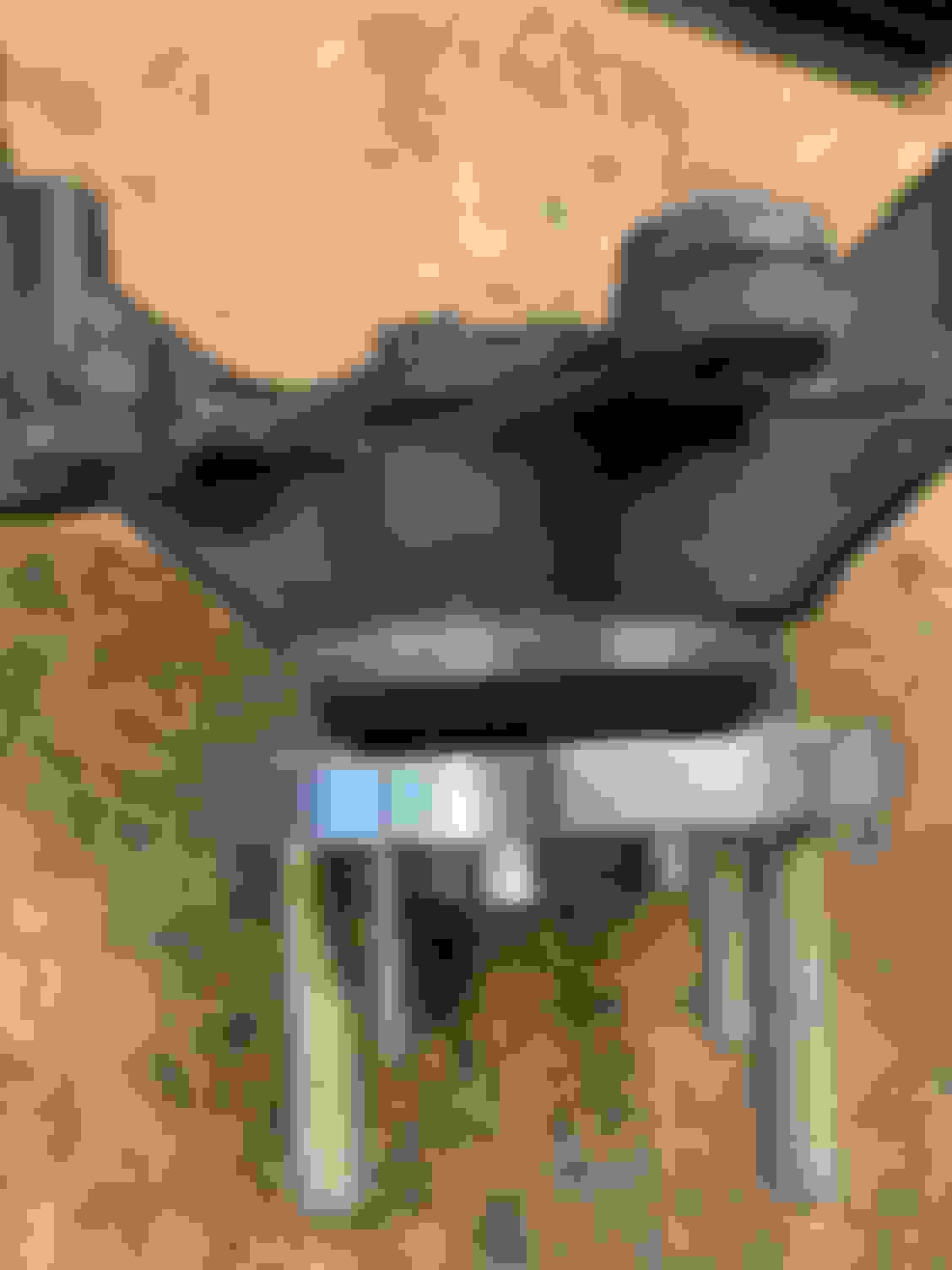
V8R Hubs...I don't believe the axle nut gets staked like the Miata one does. But, it's not a traditional castle nut either...as you will see in the pictures. Do I just stick a big cotter pin in the hole & "Send It"? Which allows the axle nut to back out until it squeezes against the cotter pin & in my opinion would just shear off. <--Very Bad.
Do I need to "drill out" the two "Castle" parts I need? (But even so, I don't think the cotter pin would lock the nut because the nut is basically past the hole.) Or am I just over thinking all of this?
Also, I only torqued this to 150 ft/lbs. thinking I needed to use the Miata torque figures, since V8R doesn't send any info. Just found out while researching this that it's supposed to be torqued to 225 fl/lbs. The nut is really already past the hole and this will make it even more so, granted it's probably only a 1/4 turn more to get that 75 ft/lbs...
One last bit of info...These are the hubs that wouldn't allow the brakes to sit centered over the rotor and needed me to shim the caliper out 1.5 mm to fit...Starting to think even more that I got the wrong part here, but would like other peoples thoughts before I reach out to V8R.
I would just call Shandelle in the am and he'll tell you what to do.
I will, just it�s going to end up taking a while before I get an answer back / I don�t think I�ve ever called there and got someone on the phone. It�s always email.
Originally Posted by gooflophaze
Which stage axle's are those? IIRC, both our stage1 and 2 used subaru staked nuts.
Stage 2...I went with the stronger than needed since I plan to track the car.
I've written back and forth with V8R a few times now and I'm a bit at a lost...(I can copy and paste the actual emails below if someone really wants to read them)...but here is the gist...
Me: How are the rear axle nuts supposed to be locked on?
V8R: V8R asked DSS (Drive Shaft Shop) if the nut was self locating (I think autocorrect issue and he meant self locking) and they responded: "Yes, once torqued to OEM Axle Nut specs it's not going anywhere as long as the bearings and everything is solid."
Me: I'm uncomfortable with this answer. The nuts are not self locking, they easily spin on to hand tight. Also, this is a track build and I run over curbs, there will be a time everything is not solid. I then mention that I still think there is an issue with the hubs...now we have two points (calipers won't line up without a shim) and the cotter pin hole is not right, that the hubs are an issue. I ask for the following: Either to return the hubs and get a new set, or 1st measurements for the hubs so I can see if they are correct or not.
V8R: "The original joints, which you have, were from a Mazda 626 and that is why the retaining hole is not flush. ... The best option would be to review the hubs first. I don't believe the issue is there, but it would be good to review it. If you can provide the hub measurements I can confirm them to our CAD model."
I'll be taking some measurements and sending them to V8R. That said, does anyone have pictures or can take a picture of their rear wheel hub and nut (that has the stage 2 Getrag kit, built greater than 6 months ago...they changed up how they build them.)
Do you all feel this is a safety issue or am I making a mountain out of a mole hill here?
I don't see why you couldn't stake it if you wanted to. Not an expert here, but it seems like you could line up one of the nut indentions with the hole on the bolt so it actually locks it in place when you hammer it.
It also looks like DSS sells axles with a traditional nut that is meant to be staked. I'm willing to bet you could call them and get a couple new axle stake nuts for pretty cheap if you wanted.
Unfortunately, It's not torqued on all the way in the pictures and pretty much past the hole already. I could get a shim for behind the nut and that would possibly line it up. That is a possible solution, if I can stake it (the nut is pretty thick). That would probably line it up to use a cotter pin if I wanted too.
That said, why hasn't V8R or DSS stated to do that? (I even brought this up in my first email to V8R, that I don't have a washer / shim behind the nut incase I was supposed to have one.) Instead I'm told it's a self locking nut, when it's pretty obvious it isn't.
Maybe I have the wrong expectations, but every time I shim something back there it has cascading effects. For example, because I had to shim the brake caliper, now I have to use spacers to keep the wheel from being to close to the caliper. (It's 1mm from touching without the spacer.) Now because I put in the wheel spacer, I have to roll the fenders (which I was going to do eventually anyway, when I go to a 245 / 10" rim) but you are getting the idea.
Sorry, I'm a bit frustrated and please don't think I'm taking any of this out on you. I really appreciate the help & your solution is a really good one.
This looks like a top lock distorted thread nut. Since I am terrible at explaining things....
Distorted thread locknuts have a section of thread that is shaped so that it must elastically deform to mate with the threaded shaft. This causes a surface normal force and therefore the increased friction required for locking. Because their construction is all metal, they continue to work at elevated temperatures. Distorted thread locknuts may be categorized according to where the distorted thread is located or the shape of the distortion. For example, enter lock nuts have a distortion in the center, allowing them to be started from either end, while top lock nuts have a distorted thread at one end.
Basically once you tighten this down, as long as you have the nut past 1 thread, the locking mechanism is working. I agree that it looks like you are supposed to stake the nut but that is not how they are designed to function. If you look at the nut from the top down, through the hole, you will notice the flats where the indents are located. I snipped the pic you uploaded and (poorly) drew where you can see the flats in red and the rounds in blue. If you torque this to spec and there are no threads showing then you have a problem! Hope that helps!
Yes, I now see that it is a lock nut (which makes me feel a lot better about the situation). I was wrong and will let V8R know I was wrong. I couldn't see that with it already threaded on, once removed I can see that easily enough. I only had the nut torqued to 150 ft/lbs, and it's supposed to be 225 ft/lbs. (I need to go get a bigger torque wrench.) I'll do that here in a little bit, but I don't have threads showing at 150 ft/lbs & I doubt I get more than 1/4 of a turn more to hit 225 ft/lbs.
So...I still think I have an issue, but before I go any further down that path, let me torque these to 225 ft/lbs and report back my findings.
I got a torque wrench that would do 225 ft/lbs. It was a bit of a pain trying to torque with no parking brake and the car in the air. I had to put the tires back on the car and lower it so I had the weight of the car to help before I could get that click. (someone might need to go to the gym too...that actually required some muscle.)
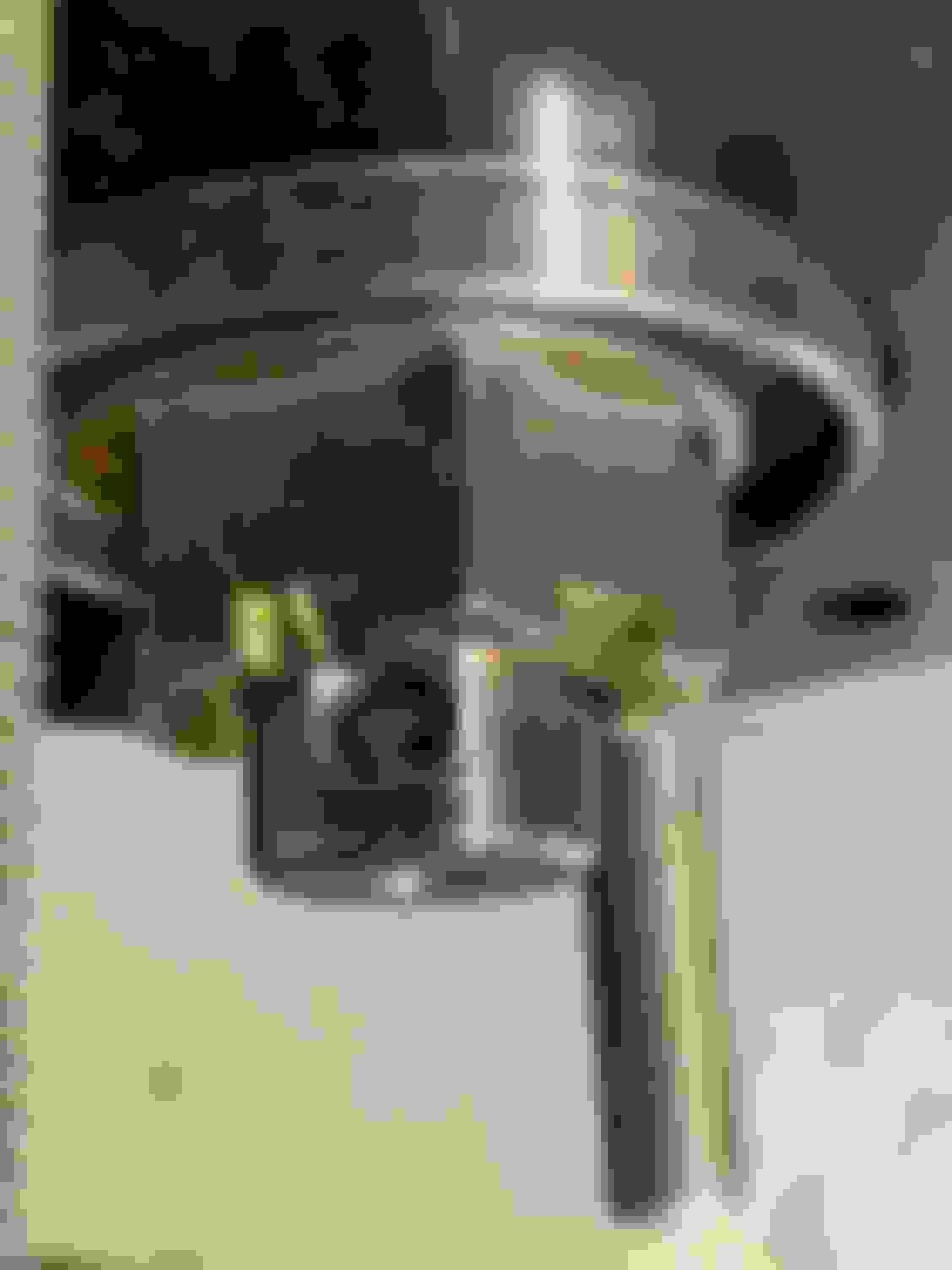
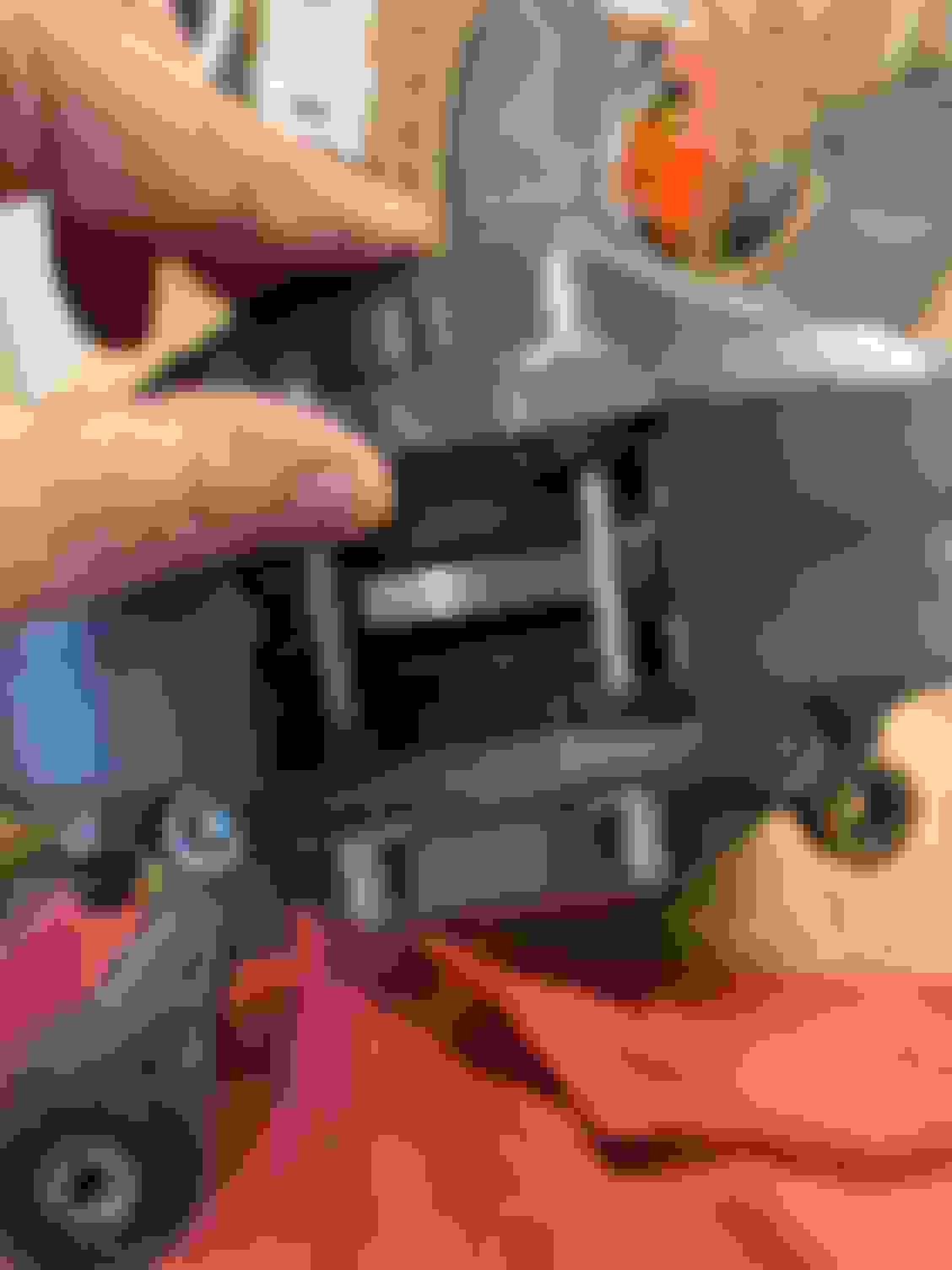
Here's a picture of the nut where you can see what UnderPSI (thanks again) was showing above.
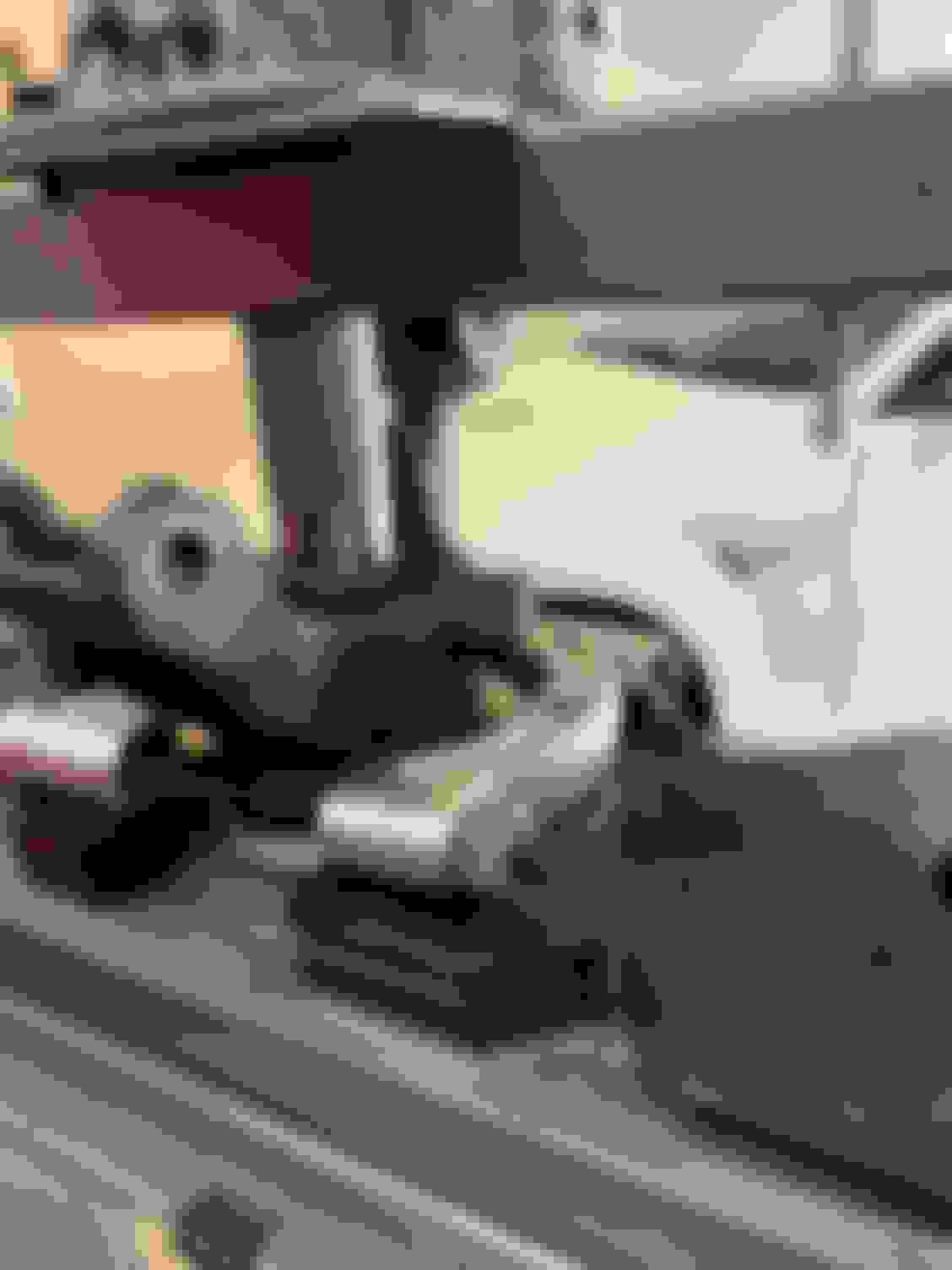
And here is what the nut looks like torqued to 225 ft/lbs. Unfortunately, I don't see any threads and at 225 ft/lbs, I can't tell if it's locking at all or not. Normally you can feel resistance when you get to the locking part, but I can't tell.
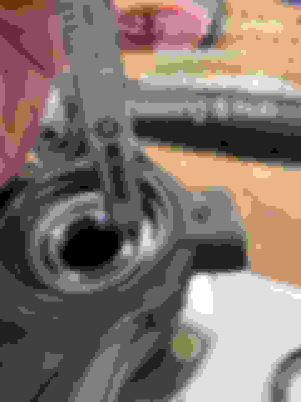
I also added a picture of the half shaft threads so you can see where they begin...which is basically right at the edge of the hole, so it's close.
I'm still thinking something is up with the hubs. (Although I've been wrong before & will be again, so if anyone in MT world thinks differently I'm happy to entertain those thoughts.) Since I needed to shim the caliper 1.5mm out further to center it, that would mean I should get 1.5 mm more thread engagement if the hub was sitting where it properly should be. The threads look to be 1.5mm, so that's 1 whole extra turn of the nut. I don't think that would give me a full thread sticking out, but it would definitely be a lot closer.
So at this point, I guess I need to press one of the hubs out of the knuckle and take a bunch of measurements. I can't see any other way of measuring the hub, unless someone else does. Sort of sucks that I have to take things apart and destroy a bearing & seal to measure everything, but I need to get this resolved and I've already sunk a ton of hours trying to figure out these hubs. I'm ready for this part of the build to be solved.
On Saturday I did a bunch more measurements & ended up removing the hub from the knuckle to send all these measurements to V8R. I thought it easier to just put all of the info here and send V8R the link instead of trying to attach all these photos to an email. Nothing that exciting to see here.
Axle Nut & Locking
So I took some measurements to see if the Axle nut is locking or not. (Spoiler alert...It's not able to thread on enough to lock)
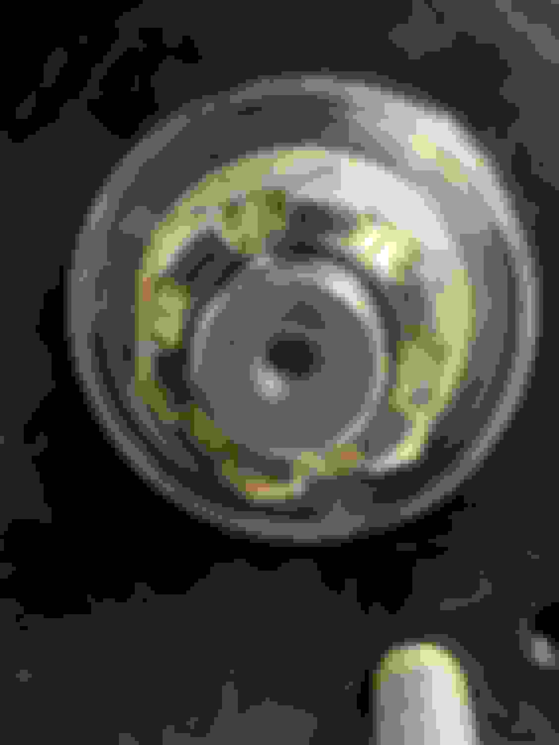
Axle Nut torqued to 225 ft/lbs (crummy picture, sorry)
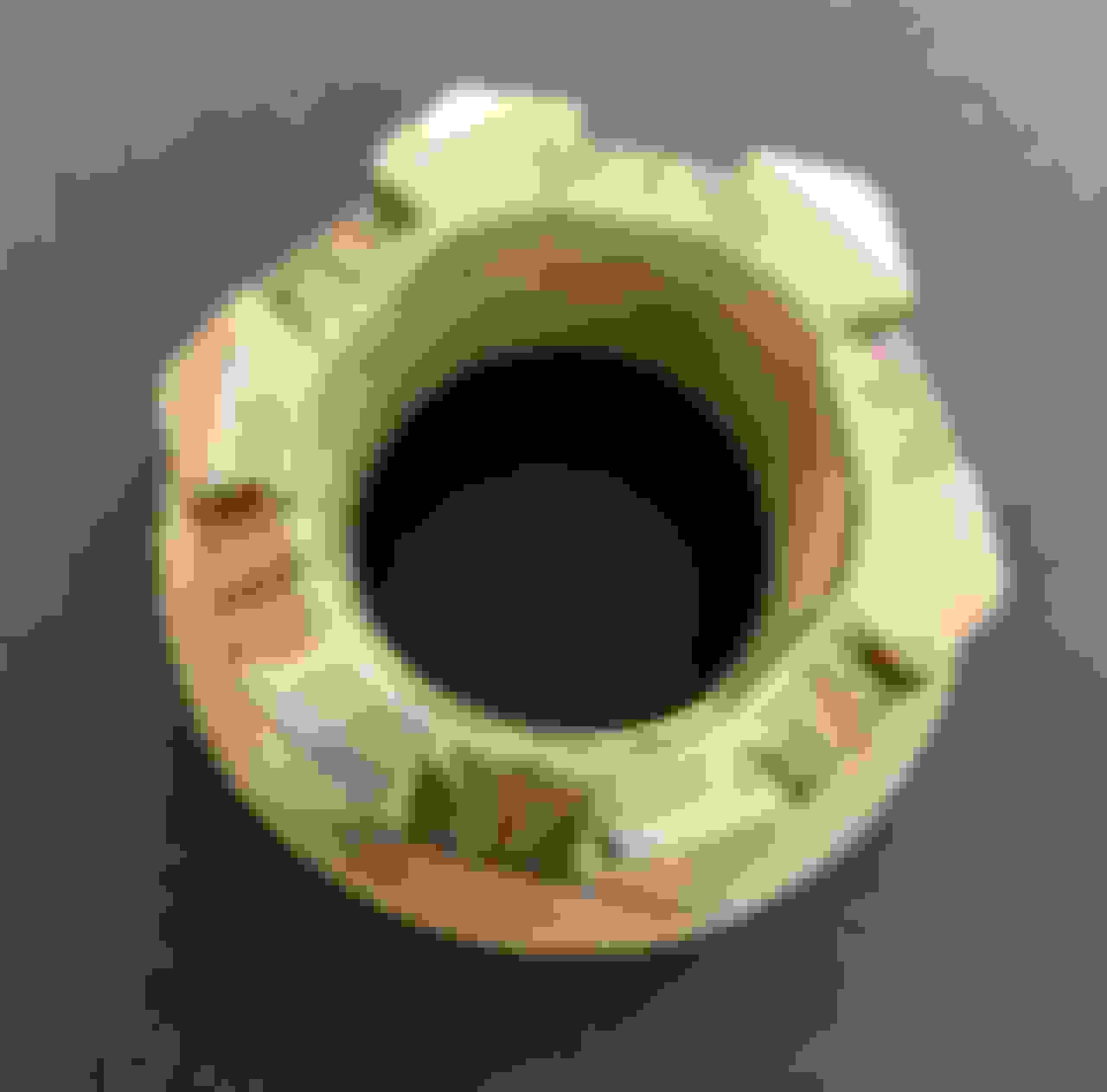
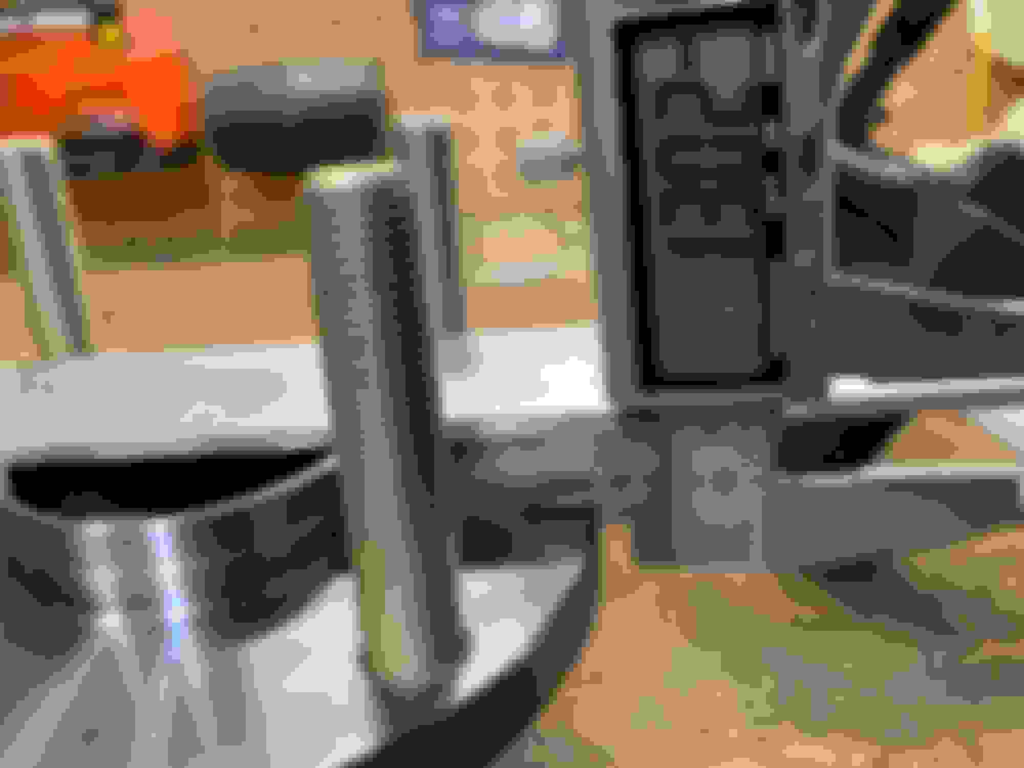
Axle Nut spun on by hand till it stops (nothing but nut & half shaft)
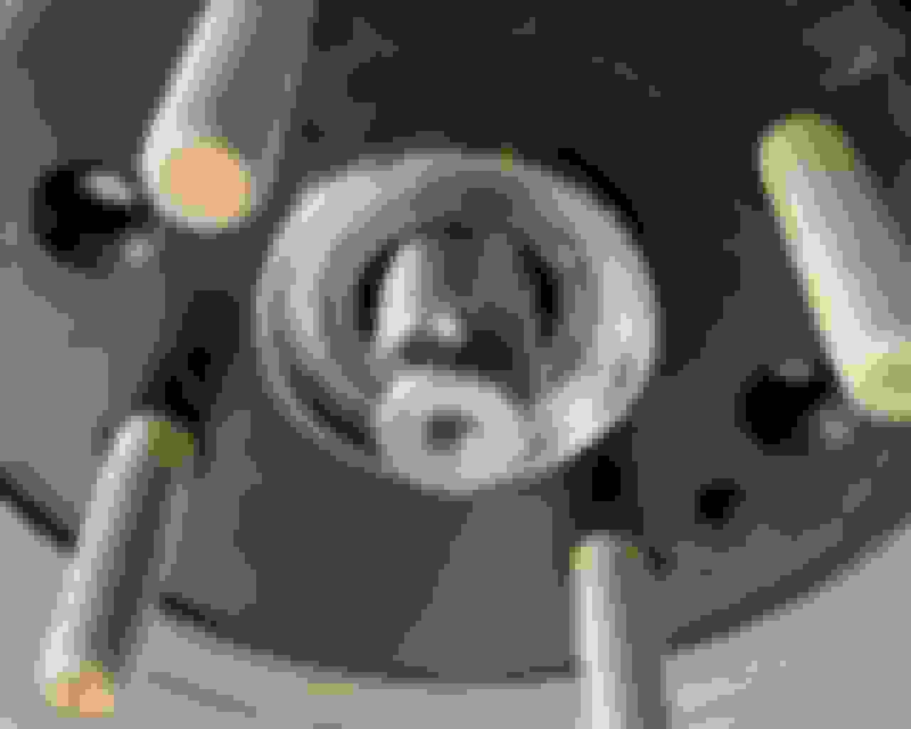
Axle Nut wrenched on with just the hub (no bearing or knuckle) and threads starting to show (The hub could move still about 1mm in this picture before it would be "tight" against the half shaft)
Hub Measurements & removal from Knuckle
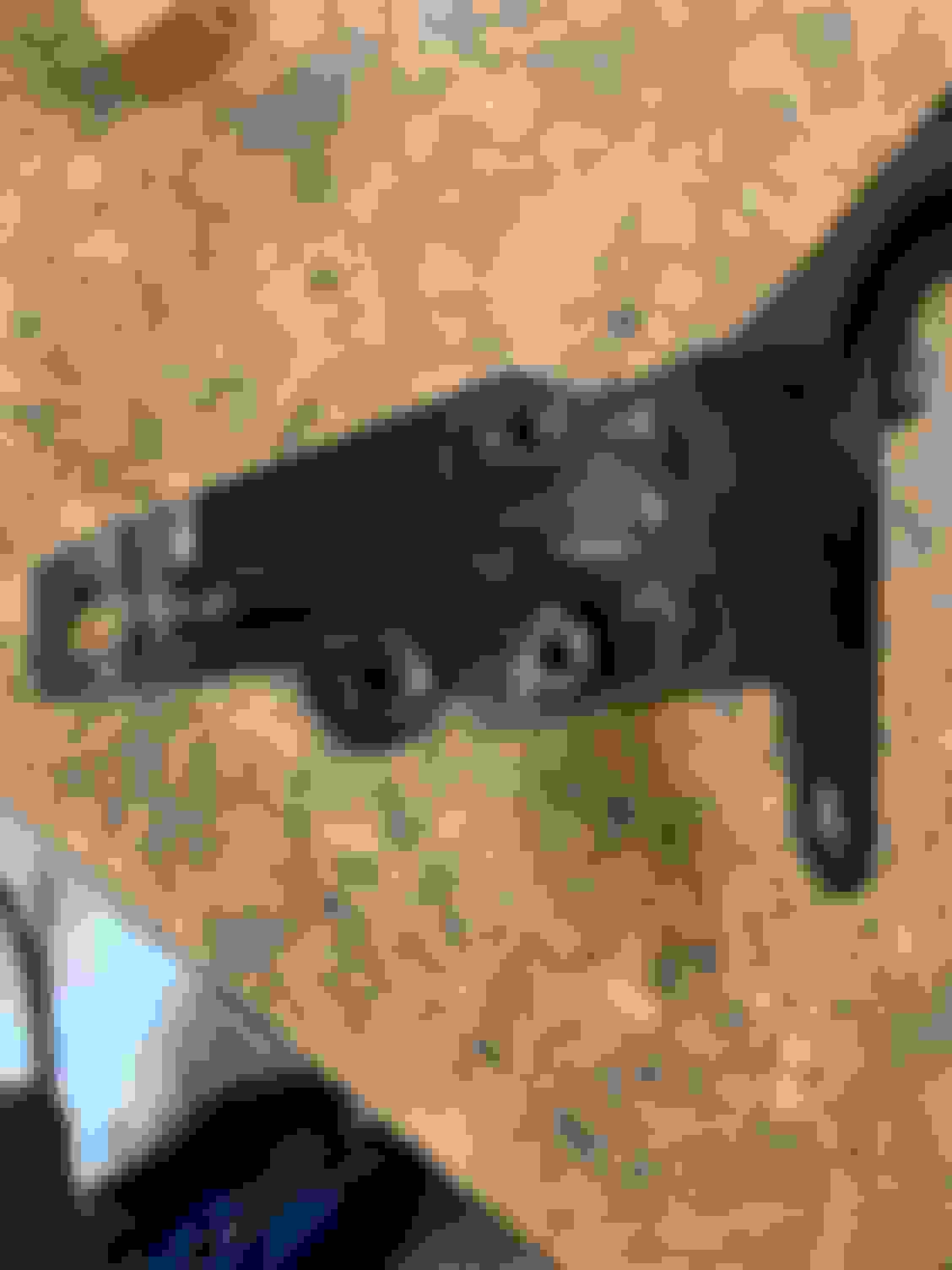
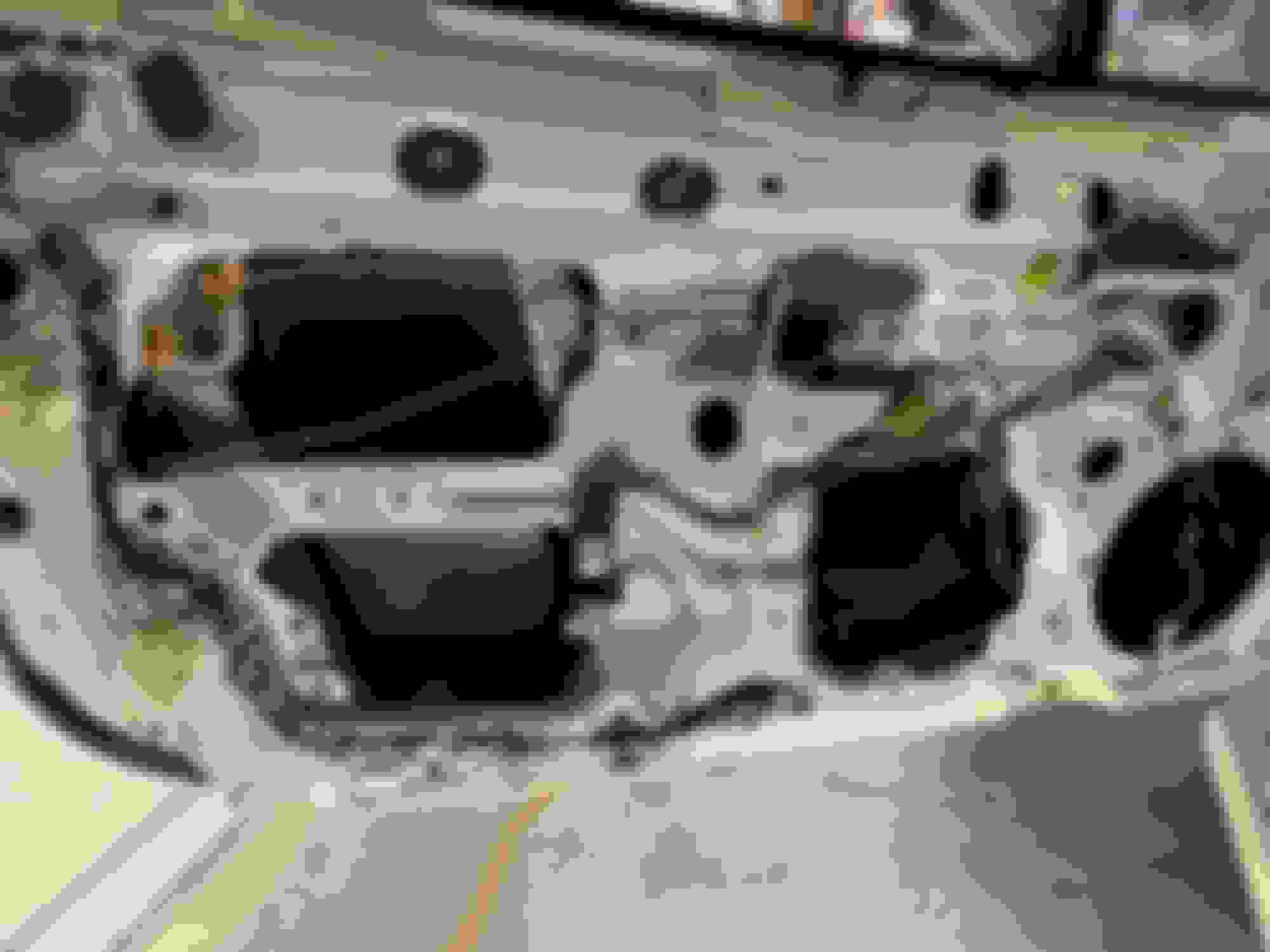
Here's the Knuckle removed from the car
Distance between Knuckle & Hub
Thickness of Hub
Backside of the Knuckle (Hub, Bearing, Seal still attached)
Removed the rear seal...Distance between the backside of the bearing (it's taller) and the hub. Sorry, I had issues getting this measurement, so you get a range. Note: Timken Bearing used here
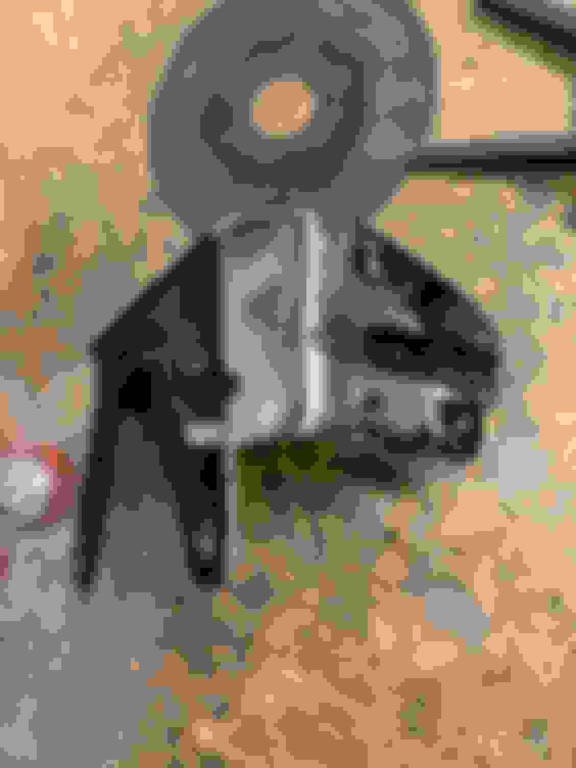
Pressing out the Hub
Knuckle with Hub pressed out. You can see bearing was in proper place with the C clip.
Hub with bearing race (you can see the bearing was pressed all the way onto the hub here & the measurement of the "ridge")
Bearing Race Length (the half that is still on)
Back of Hub Length
Front of Hub Length
Hub Overall Length
Hub has MZ5 marked on it
Half Shaft to rear of Knuckle (when still in car) @ 225 ft/lbs
& A closer shot
That's All Folks! for the pictures & measurements.
You are certainly doing a good job of trying to track this down. I am familiar with this type of fastener but I don't have extensive experience. Hopefully V8R can clarify what is going on here and get it resolved ASAP!
Still trying to resolve my issues. V8R responded earlier in the week that they believe the Hubs are good and not the problem. After some more testing on my end, which I'll document below, I'm in agreement with them. Now I believe I have two distinct issues, rear brake calipers not centering correctly & axle nuts not locking. Not one item causing both issues.
Testing the Hubs
For some reason, it never dawned on me that I have an extra set of knuckles with stock hubs in a box in my garage AND a stock Miata sitting in my driveway with stock hubs so I could measure & test items. Thank God I'm Pretty...Right?!?! SMH
So the main measurement that I took was from the bolt holes that the caliper mounts up to, and measured to the front of the hub on both the stock hub & the V8R hub. I just clamped a piece of flat stock to the back side so I could get an easy measurement like this...
The two hubs ended up being basically exactly the same. I was 1/10th of a mm off from each other, which is probably more user error with measuring than actually even off from one another.
Since I'm looking for answers, I decided to be a belt and suspenders guy and also installed the rear brake caliper & rotor to the stock hub to see if it still had the centering issue. As you can see here, It's still not centered
And here it is after I shim the bracket with a 1.6mm Grade 8 Washer.
Here's a picture of the shims...
Testing the Brake Calipers
Previously the running theory on why the calipers were not centering was because the hubs were not pressed in all the way. I felt pretty confident they were pressed in all the way, and when I pulled the hub out of the knuckle I was able to confirm that they were pressed in properly. With testing against the stock hub and having the same issue, I now can deduce the problem is in one of 3 potential places.
1. The caliper was made out of spec. (I have no way of checking / testing this, but this to me seems least likely)
2. I purchased the wrong rotors / the rotors I purchased are out of spec.
3. The V8R bracket is not the right size to center the caliper over the rotor.
Since the only item I can somewhat "easily" test is the rotors, I went and purchased another set of sport rotors to see if its the rotor or not. I had the same "won't center" problem with the new rotors and with the shims, everything centered up correctly.
Not the best of pictures to see that it's not centered, but it's the only one I could find with this rotor
I can still shim this and make it all work. I wish I didn't need to do that, since I now need to run a wheel spacer with my 9" wheels, but my intention is to ultimately run 10" wheels, and I shouldn't have any problems once I go big.
Axle Nut
I really didn't have any other "tests / checks" for this. I can't use my stock hub w/ knuckle to test since the splines are different. My only other thought was to possibly remove the rear seal on the knuckle and maybe that will allow the half shaft to press in further and I could get more thread engagement. I really think this is wishful thinking on my part and decided to not even bother trying it.
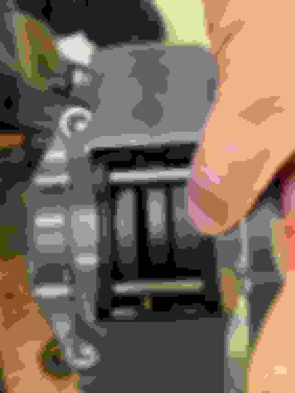
Since I've been giving this a bunch of thought...I believe the half shaft "stud" is not long enough for the axle locknut. Previously when I took the measurements. I had about 1mm left over once I had the threads just starting to show. But, that 1mm left over was without the bearing on the hub.
Arrow points to the 1mm of space left between the hub and the half shaft with no bearing or knuckle.
When the bearing is "attached" to the hub, there is a 2.75mm - 3mm where the bearing sticks out past the hub on the backside.
Subtract my 1mm left over from the 2.75 - 3mm that the bearing is proud of the hub, and I'm missing 1.75 - 2mm's worth of threads to get the nut on with the threads just starting to show. Add an extra thread (1 mm) to go past the nut & I'm really looking at being 3mm short.
So, I'm thinking this is the issue. I'll reach back out to V8R and get their thoughts on the matter.
While I wait for a response on my axle nut issue, I figured I could write up some other items I’ve completed. I'm sort of jumping ahead here, since this was completed the weekend I took all my measurements. (I still have some other items I did earlier this year), but this one is semi fresh in my mind, and isn't dependent on any of the work that I still need to write up / discuss.
This is what I started with...Master Cylinder and 2 of the 3 OEM brake lines installed. (Rear brake line & the passenger side front)
Bracket First thing I needed was a way to hold the "T" that's used to connect the two front brake lines to the Master Cylinder (OEM Master Cylinder has two front brake connections) and a way to hold the rear brake proportioning valve. So, I pulled out the original bracket that Miata designed for the OEM proportioning valve.
I did a quick test fit, but the LFX is a lot wider than the BP, and installing the proportioning valve on the bracket as is (like I did on my “stock” Miata) would have been touching the valve cover. So I decided to move "arm" of the bracket 90 degrees. I was going to bend it at first, but the groove in the metal made it too sturdy to bend, so instead I cut it off and tack welded it back on at 90 degrees. (sorry no picture of this) This semi worked, but the two nuts already on the bracket (that I decided I was going to use) were in the wrong places. (Top "nut" was forward and I needed it back, and the bottom "nut" was back and I needed it forward.) <-- These were in the wrong places to connect the brake lines from above easily. So I cut off my tack welds and flipped the arm over to get the nuts in the right place. I also added an additional nut, since the Wilwood Proportioning valve has two screw holes.
From there I did a quick test fit...Looks Good!
I pulled it back off, and cleaned it up some, by welding it up and cutting off the forward most tip that was no longer needed.
A little bit of spray paint & bracket was done.
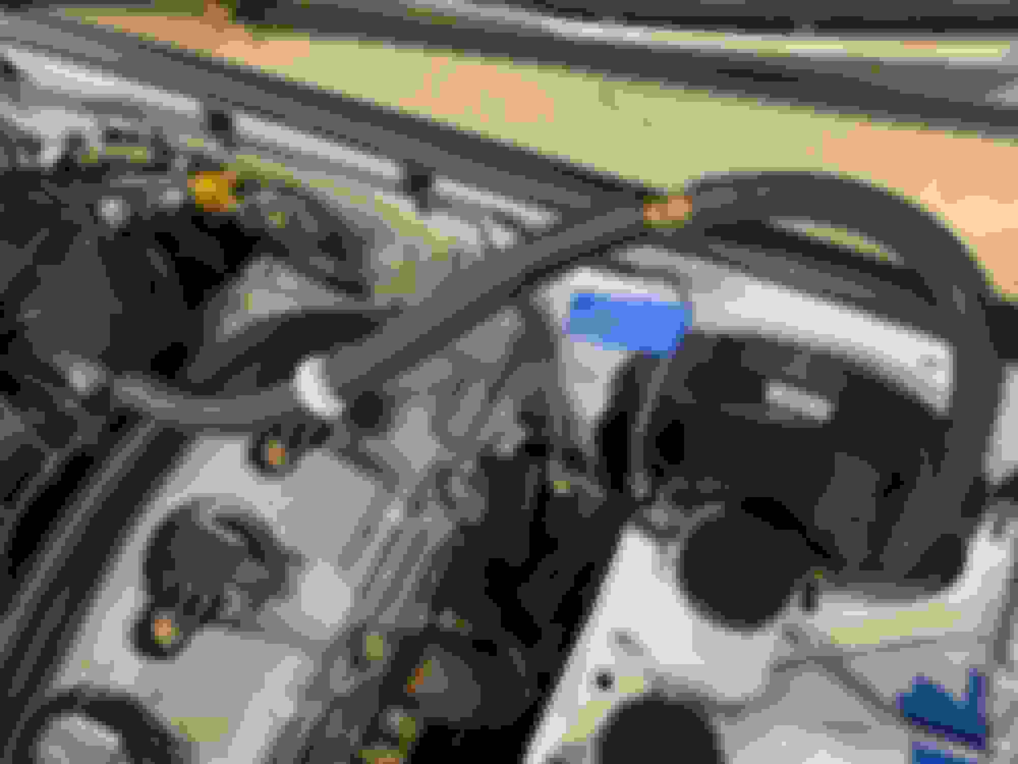
Master Cylinder Vacuum Hose
I installed this hose a while back (and made these changes a while back) but never wrote home about it.
The Master Cylinder vacuum hose on the Miata is smaller than the vacuum hose connection on the intake manifold. I’ve forgotten the sizes off the top of my head, but I went to Lowes racing and purchased a reducer with two barbed ends to connect the two different size hoses.
I also needed a check valve added to the hose, so vacuum can only go one direction. On a stock Miata this check valve is built into the Master Cylinder vacuum hose. My old stock hose was starting to dry rot, and funny enough, it didn’t have any check valve in it. So I purchased a brake check valve for some random Chevy and installed it inline.
You can see the check valve & the barbed ended connector that reduces here
To hide the two hoses being different sizes & spliced together, I connected the two hoses right where I mounted the hose to the back of the firewall. This hides the hoses being two different sizes by the adel clamp and just looks cleaner. Here’s this hose all mounted up.
Brake Lines
Let’s start with the worst part of making brake lines….The cheap *** generic brake flaring tools. In my opinion, they should all be melted down and made into rubber dog ****. Destined to still disappoint children everywhere, since they would fail at that too.
Best I could get out of the dog **** flare tool.
After wasting a bunch of time and never getting a good flare & then breaking the die…SMH I went searching online and found a tool that actually works. (if you are building brake lines…buy it and be happy! I picked this one up from Summit but Amazon and other places sold them too.)
What every flare looks like with this tool.
The other issue you run into is SAE 3/8-24 fittings needed for the Wilwood parts and Metric M10-1.0 fittings for the Miata OEM parts. (Lucky enough, you can use 3/16” brake tubes with both of these fittings) I hate mixing and matching, but it's what you have to do in this case.
V8R sends a couple brake lines with the Master Cylinder kit. They were too short for my setup, so I cut the ends off to re-use the fittings and made my own lines. The first line I made was from the Master Cylinder to the “T” for the front brakes. The Master Cylinder side needs a 3/8 - 24 fitting and the “T” side needed a M10-1.0 fitting.
My main issue with this line (and for some reason I didn’t take any pictures of this) was that I couldn’t get the line to thread into the “T” The fitting would work on it’s own, but with the flare I couldn’t get it started. It was all too long. That’s when I learned about Bubble Flares (normally used on Metric European vehicles) using a different fitting than a double flare (dbl. flare is what the Miata uses).
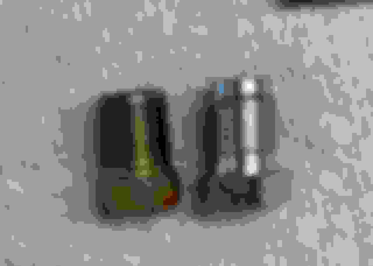
Silver one is used for Bubble Flares, notice the "tip" is different. The Gold one, is the Metric fitting that works with the double flares.
I didn’t want to waste time buying / waiting on new fittings, so I took one of those OEM short lines that the V8R lines were to replace and cut the fittings off from it. Then I cut off the flare from my new line, put the correct fitting on it, and made a new flare…That solved my problem and I had my first new brake line done.
Here I was measuring length and after getting my bend in the right spot.
The next line was from Master Cylinder to the proportioning valve. (3/8-24 fittings on both sides) I wasn’t sure if I could get the first 90 degree bend to happen before the little brace on the shock tower. (I think it use to be where the cruise control was bolted to the body…) Anyway, I took a coat hanger to bend into shape and measure how long of a line I needed to go around it. I figured this was the longest length I would need, if I couldn’t take the more direct route over it.
Lucky enough, I was able to get a 90 degree bend about a 1/4 inch above it and had a much more direct route / the route that I wanted to take.
For the OEM rear brake line that attaches to the top of the proportioning valve, I needed to cut off the old flare, remove the Metric fitting and put a 3/8-24 fitting on the line. This would have been basically impossible with the rubber dog **** brake flaring tool. I couldn’t get a good flare on the bench with the tool being held in a vice. I was a bit worried about making this flare, but the good flaring tool worked great and it was simple.
Cutting off the old flare so I could change the fittings
New SAE 3/8-24 fitting attached with new flare at the end.
After I had the new fitting & flare, I bent the line a bit to get it to connect. What I thought was going to be the hardest fitting, ended up being one of the easiest.
The only line left was for the drivers side front brake. I pulled out the stock line and test fit it. The line would need to be bent a lot, and also ran up alongside the exhaust down pipe.
I decided to make my own here. Its still a bit closer than I want, but it’s a good 1.5” further away from the pipe than the stock line was. The stock line had a rubber covering on it incase it contacted the body of the car. I mimicked that by using some shrink wrap tubing. To get the thickness, I put a second piece of tubing over the first. This might all end up in a sticky mess vs being clever. We shall see.
Stock Line in "Grey" with my line in "Copper"
All of the brake fabrication is done to get the car running on the street!
What’s left on the brakes...
1. I read somewhere that I need to pull a spring or something like that out of the master cylinder. It’s down where the brake line attaches to the Master Cylinder on both the rear and front lines. (I need to find that and read up on it again)
2. Bench bleed the master cylinder & then bleed all the lines.
*** Items below to be done at a later time once I have car running ***
3. Install Brake Proportion Valve Cable into the Cabin
4. Modify the Singular Brake Ducts so they only point into the Hub
5. Install Brake ducts hoses
It's been a bit since I've updated, but I have been working on the car some...Ordered a bunch of electrical stuff from amazon, ebay, del city, summit, etc. last week & just waiting on my Del City package to arrive so I can get to work on losing what little hair I have left wiring. That was going to be the plan for this long weekend, but I ended up doing everything else but... Also still working with V8R on the axle nuts on the half shafts. They are working with the Drive Shaft Shop to come up with a solution for the threads. I'll let you know how that will be solved when I know.
Anyway...nothing super exiting below, but this should have me up to date on everything completed under the car as of today except for exhaust (which I'll put in a separate post.)
This is work that I did from January of this year till "today" under the car.
Fuel Filter Moved up a little higher...This was already discussed if memory serves, but I moved the Filter up a little higher so it was better protected.
Diff Vent hose I left this as a super long hose previously, and I didn’t care for an open end. So I purchased this little vent valve and installed it after cutting the hose a bit shorter. Then I tucked the whole line up at the top of the rear subframe and semi zip tied it all in place.
Here you can see the little vent attached before stuffing the hose back up out of the way
In this really crappy picture, you can barely see the hose all tucked up high and out of the way and barely see the zip tie on the bottom right of the picture holding it in place too.
Rear Subframe Brace I reinstalled this…(about 50 times while building the exhaust. It has to come down to get the exhaust out, but everything is very tight around the diff & this brace that I kept needing to install/uninstalling it to make certain everything would fit without hitting.) I have not idea if this even does much or not. It seems like a lot of guys leave these off, but I can see why you would when trying to install a 3" exhaust around it & the diff.
Here's a picture (got to have picts) of it loosely held in place since I kept having to remove it to work on the exhaust.
Brake & Fuel Lines under car mounted. Previously these were just hanging under the car & I needed to mount them properly. I thought of a few different methods of doing this including building little brackets like Gooflophaze did, but in the end I used some self taping screws for the brake line and just some bolts through the floor with nuts on the other end for the fuel line. This was the quickest way of doing all of this and got the job done. I also added some rubber tube anywhere the fuel line looked like it might cut something in two.
Here's the lines going towards the back of the car
I don’t like that I have the two lines crossing up at front, but I wanted to keep the fuel line away from the exhaust and this was the best way to do it. I also ran the radiator overflow dump down to this point & used one self tapping bolt to hold both of these.
Another angle of the shot above...the above shot looks like the fuel line is a lot closer to the bolt then it really is.
Gear Oil does anything smell worse?!?! I had to fill the diff with fluid and drain & fill the transmission. I put 75W-140 (red line with limited slip goodness) in the diff & 75W-90 (royal purple) in the trans. I need to change out the diff fluid again to a lighter weight oil, but I'm cool with running this for a little bit and then swapping it... And those cheap little pumps that look like a soap dispenser always seem to break after the 3rd or 4th time I use them. Of course, it broke on me while filling up the diff. I thought about buying a bean sprayer and converting it to "pump" fluid, but I figured that would be a mess to clean up. Ultimately, I ended up buying another one of those cheap pump kits. This one looks a little more like a hand held bicycle pump. It doesn't pick up the oil in the bottom of the bottles as well, but only needed 15ish pumps to empty the bottle vs the 100+ the "soap dispenser" version seems to need. That's a small victory in my book. Only other item to write about here...be smarter than me & do this before installing these parts under the car.
Clutch Line The clip to hold the hose was a bit of a pain to get into place under the car. This is also something that if I was smarter and did again, I would have had the line installed / clipped in before installing the engine / trans so I didn’t have to do this under the car.
Not crazy about how tight this line is & the U turn it makes immediately, but it is what it is I guess.
What's left under the car...
Need to torque & loctite the driveshaft (was just waiting incase it needed to be removed for some reason, but its getting to be time.)
Some odds & ends with the exhaust (But the odds & ends can be done after I have the car running & driving)
Bleeding the Clutch
I'm a happy boy to have under the car basically completed. I envy all you guys with a lift!
Figured I'd try and get a second update in tonight too. The items below gets the "interior" up to date as of today. Over the past few months, I only spent a couple days doing "interior" stuff, and most of it is stuff you would never really notice or see, but for the sake of the build thread...
Roll Bar
Ultimately, the idea is a cage in this car, but for the next year or so, it's going to be a road / track car, so a roll bar is the idea here. Someone posted this one used and I bought it without knowing if it was a hardtop version or not. (I figured the worst case was I would just resell it.) It turned out to be a Hard Dog..."I can remember the rest of it's super complicated and makes very little sense roll bar name" but its a rollbar for a NA with the soft top. While doing my research, I found out that this bar will work under a hardtop, just the side latches have to be bolted in. I plan on bolting in the hardtop anyway, so I'm good & decided to install the roll bar vs sell it.
Since there are multiple tutorials on how to install a roll bar...I'll just highlight a few things that ended up helping me / were different.
First, I had a hard time trying to get a drill bit and extension to fit and drill out the holes from the top. You really just need those holes as a pilot / guide, and then you can drill from below. I found that using a self tapping screw drilled out the holes so much faster & easier. (along with allowing me to get the drill to fit.) So...something to try if you can't fit the drill bit in there either.
The secret weapon...
Two holes drilled out using the self tapping screw for the roll bar from above
Second, the kid I bought the roll bar from, only had 3 of the 4 backing plates and missing a few bolts. (He told me that they weren't needed...SHM...to be 17 years old and invincible stupid again.) I ended up buying a piece of 3/16" steel and made the missing backing plate.
I found that I couldn't get the bolts to line up nice and straight on either backing plates. I didn't like the idea of running them at an angle, so I pulled out my dremel and elongated the holes a 1/16 to 1/8 of an inch longer. This allowed the bolts to hang down straight.
I only elongated the slotted holes on the backing plates...You can see the bolts sitting straight now.
Besides that...everything was business as usual with installing the roll bar. Just take your time.
Still needed to be installed in this pic, but gives the idea of what it looks like all finished up. (I forgot to take a picture when I was done.)
Removed the Fuel & Trunk Release
I pulled this out, mainly because the cables were in the way of getting the roll bar installed, but it's no longer needed & saves half a pounds worth of weight. The trunk can be opened with the key (and I saw on the "Thingverse" they make a plastic tube / insert you can print up and install in place of the lock that allows you to turn it by hand to open. I like this idea even more...Then I don't have to worry about a key with the car.)
The Fuel release is easy enough, if you reach up there you can easily pull a little lever to get the fuel door to open. I may add a line to it / or cable that comes out at the brake light for a faster opening, but for now...this works.
You can't easily see this lever, but if you reach up there, you will feel it, it doesn't take much to pull it to open the fuel door.
Door Panel
I had already removed the door panel & speakers from the passenger side, but still needed to do the drivers side. The hard part is just getting all the nasty tar off that held the moisture barrier in place. I don't know why, but I'm really surprised at how much more room you have with these things removed. I wanted to start tearing apart the door more, but I'll leave them like this for now. I want to keep the windows working for a little while longer.
I had half the tar removed and half still on here. I used WD40 this time to remove it. Last time I used Mineral Spirits. They both seemed to work about the same.
Mirrors
The previous owner had put a lot of Chrome and cheap pepboys gimmicky car "stuff" all over the car, the chrome is fine on an old 50's 60's car, but on newer cars, it isn't really my taste, and the cheap pepboys gimmicky stuff is really not my taste. Anyway, I've been slowly removing this stuff as I've been working on parts, but I haven't gone out of my way to remove items that I haven't touched. Anyway...These little blind spot mirrors that basically made the real mirrors no longer work were on this list of items. They kept reflecting back at me like a siren song while I was cleaning up the tar on the door & I couldn't resist removing them. So it took a while, but I slowly pried these things off & cleaned up the residue afterwards.
AIM Dash Sizing
I'm thinking about buying an AIM Dash. I'm gonna need gauges & want a lap timer too, so this seems like the best choice. I found the two different sizes that I'm thinking about and made cutout of them to test how they would fit. I want to go with the bigger 10" screen, but It looks like it might be cut off a bit too much trying to make it fit. I haven't made any decisions around this yet, it's not needed to get the car up and running, but I wanted to get an idea for now.
10" I drew out the screen size & mocked up some lights it also has in the frame to see how much would be cut off. I also think this will be hard to fit depth wise too, I'll definitely have to cut the hood to make it work.
6" This size would fit easily
Other odds & ends
I re-installed the dead pedal, since I ran across it while looking for something else. I also pulled out the 3 covers for the package tray. I installed the fuel hose cover, since I didn't need back in there any longer. The fuel pump/tank cover I set to the side since I know I still need in there to wire up the fuel pump. I also didn't install the "package tray" cover since I still need access for the wiring, but I cut it so it would fit now with the roll bar and just set it in place for now. I want to paint these pieces, but that's on hold until after the car is running.
Interior Items left to drive the car
The electrical switches / but that will be part of the electrical write ups
Seats & belts / harnesses
Steering wheel
I'll probably just steal the seats/harnesses & steering wheel setup out of my current track Miata. This would be the fastest for getting the car running for now and let's me concentrate on other items. Ultimately, I want a halo seat for the track, but current setup would be a good interim solution till I'm ready to put in the drop floor, cage, etc.
Another angle of the shot above...the above shot looks like the fuel line is a lot closer to the bolt then it really is.
Nooo! Reverse that protection - the sleeve should go on the SS line, where it will move WITH the SS, thus no (bugger all anyway) wearing action. The way you have it the SS line will fret the protection, in a place where you will be hard pressed to detect.
I use 3t axle stands when no hoist available, the extra height makes all the difference.
I like the idea of the 3T axle stands too. I thought about getting some at the beginning of the project, but I figured I was almost done so why bother.... (I didn't say I was that smart...)


 0
0