Notices
Build Threads Building a motor? Post the progress here.

Ian's 99 build thread

Old Apr 21, 2017 | 07:29 PM
  #901  
turbokitten's Avatar
Newb
 
Joined: Sep 2014
Posts: 21
Total Cats: 5
Default

Having looked at Ian's a lot I think the problem is that the pickup is on the left side of the tank and all the fuel just sloshes out of the sump area and into the right side of the tank during left handers... Mazda simply didn't design it for sustained 1.4 G turns followed by 0.5 G of acceleration all the way down the straight. Which brings us to what I think the right solution is:

Originally Posted by Sentic
Has anyone tried making a splash guard? something like a metal box around the pump assembly, with holes in it of course. ... enough volume to refill after a section with splash-inducing turns.
It's called baffling. There are a lot of designs out there. The simplest ones are just some walls around the pickup to prevent the worst of it:


Labyrinthine designs work better in sustained corners:


The very best ones have flappers to let fuel in from the high side, but not let it out on the low side:


The downside to the above is they require welding inside the tank. It's a great idea for a new setup, but really a pain to add into the OEM tank.

Another solution is to add a swirl pot / surge tank:


This is supposed to work flawlessly, but it requires two fuel pumps and a lot of pressurized fuel fittings outside of the main tank.

The most practical solution may be the Holley HydraMat. If they live up to the hype then $200-300 you get a bolt-on good-enough solution. https://www.holley.com/products/fuel_systems/hydramat/

All of the above is based on my research into ways to solve this problem. I don't actually have any experience with any of these so I'm still eager to hear from anyone who's tried solving this on a Miata.
Old Apr 21, 2017 | 07:34 PM
  #902  
turbofan's Avatar
Supporting Vendor
iTrader: (1)
 
Joined: Sep 2010
Posts: 8,146
Total Cats: 1,087
From: Lake Forest, CA
Default

My solution,should hacking that flange off and attaching a hose prove ineffective, will be to simply maintain more than 1/3 tank on track days.
Old Apr 21, 2017 | 07:53 PM
  #903  
codrus's Avatar
Thread Starter
Elite Member
 
Joined: Mar 2007
Posts: 5,298
Total Cats: 884
From: Santa Clara, CA
Default

Originally Posted by turbofan
My solution,should hacking that flange off and attaching a hose prove ineffective, will be to simply maintain more than 1/3 tank on track days.
That's what I've been trying to do in the short term. With the 300+ at the wheels and RR grip, I'm getting stumbling at 5 gallons left, which means it's probably going slightly lean without me noticing before that as well. 7 mpg on track times 6 gallons means 40-45 miles. That's 13-15 hot laps of Thunderhill, and at a little over 2 minutes per lap that gives me 30-35 minutes of hot laps.

moto IQ did a very cool surge tank/swirl pt on their FD project car, but, um, yeah. It's a lot of work.

Project [Rotary] FD RX-7: Part 3 - Fuel System (Chassis Side) > MotoIQ - Automotive Tech, Project Cars, Performance & Motorsports

--Ian
Old Apr 24, 2017 | 02:41 AM
  #904  
codrus's Avatar
Thread Starter
Elite Member
 
Joined: Mar 2007
Posts: 5,298
Total Cats: 884
From: Santa Clara, CA
Default

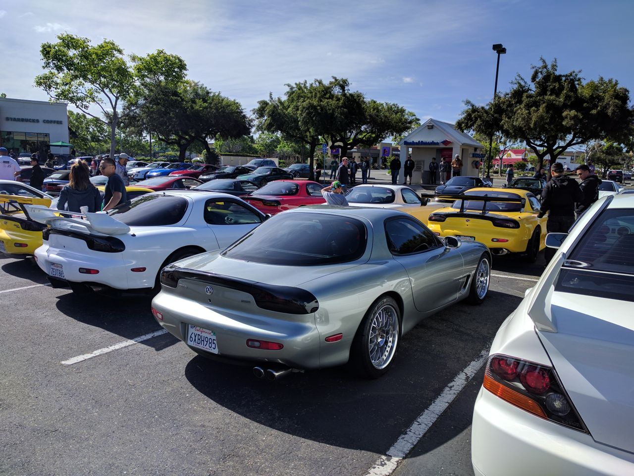
Took the FD to a "Japanese Super Car Meet/Cruise" today. I just did the pre-meet, didn't go on the big group drive up the peninsula to Treasure Island (too far, plus I don't do big group drives -- too much attention).

150 Supras, NSXs, FDs, and a few other types of cars there. It was like 1999 all over again, except without the Civics.


--Ian
Old Apr 24, 2017 | 11:40 AM
  #905  
Sentic's Avatar
Junior Member
iTrader: (1)
 
Joined: Feb 2008
Posts: 432
Total Cats: 5
From: Sweden
Default

Thats why I called it a splash guard and not baffling the tank. I'm thinking something square or cylindrical mounted to the fuel pump assembly.

But looking around, maybe aeromotives idea with "foam and bladder" is a better one.
https://www.aeromotiveinc.com/product/phantom-flex/

Or, as said before, the hydramat.

Last edited by Sentic; Apr 24, 2017 at 11:51 AM.
Old Apr 27, 2017 | 08:38 PM
  #906  
JasonC SBB's Avatar
Elite Member
 
Joined: Jul 2005
Posts: 6,420
Total Cats: 84
Default

Originally Posted by turbokitten
That's pretty amazing. Why haven't you guys jumped onto this yet?
Old Apr 28, 2017 | 10:47 AM
  #907  
aidandj's Avatar
SADFab Destructive Testing Engineer
iTrader: (5)
 
Joined: Apr 2014
Posts: 18,643
Total Cats: 1,870
From: Beaverton, USA
Default

Because for the most part the 3 people experiencing fuel starvation in miatas in the world, are in this thread. Its not exactly a common problem. And other cars have run similar setups without this issue.
Old Apr 29, 2017 | 07:54 AM
  #908  
Chilicharger665's Avatar
Elite Member
iTrader: (2)
 
Joined: Oct 2011
Posts: 1,694
Total Cats: 67
From: SE NM
Default

Originally Posted by JasonC SBB
That's pretty amazing. Why haven't you guys jumped onto this yet?
I mentioned that several pages back and got no response.
Old Apr 29, 2017 | 02:27 PM
  #909  
curly's Avatar
Cpt. Slow
iTrader: (25)
 
Joined: Oct 2005
Posts: 15,192
Total Cats: 1,398
From: Oregon City, OR
Default

I installed that mat in a fuel cell, it's a small PITA, but does seem to do that job, no more fuel starvation. The kit I used had cool glue down clips that secured the corners of the mat, but what they don't tell you in that video is that the NPT/AN hose for the pickup has to be positioned correctly so it doesn't move the mat around.

But Aidan's right, on our enduro car we use a completely stock fueling system that fuel starves on right handers, makes it back to the pits, and we fit an entire 10 gallons in a tank that's supposedly 11.9 dry.
Old Apr 29, 2017 | 03:44 PM
  #910  
DNMakinson's Avatar
Elite Member
iTrader: (3)
 
Joined: Jan 2013
Posts: 5,030
Total Cats: 861
From: Seneca, SC
Default

This is not the correct part. It meets their print on Amazon, but does not fit NB fuel rail or return.

On this part, CtC mounting holes is 32mm. On Miata parts, CtC is approximately 39mm.

Does anyone know the correct P/N? I know that people do use these to turn to AFPR.

EDIT: This one,
This One, FT061-001 This One, FT061-001
, appears to be more correct. And I found it much cheaper at Amazon.

Last edited by DNMakinson; Apr 29, 2017 at 03:58 PM.
Old Apr 29, 2017 | 07:27 PM
  #911  
turbokitten's Avatar
Newb
 
Joined: Sep 2014
Posts: 21
Total Cats: 5
Default

Originally Posted by Chilicharger665
I mentioned that several pages back and got no response.
Missed it! Here, have a cat.
Old May 13, 2017 | 11:04 PM
  #912  
codrus's Avatar
Thread Starter
Elite Member
 
Joined: Mar 2007
Posts: 5,298
Total Cats: 884
From: Santa Clara, CA
Default

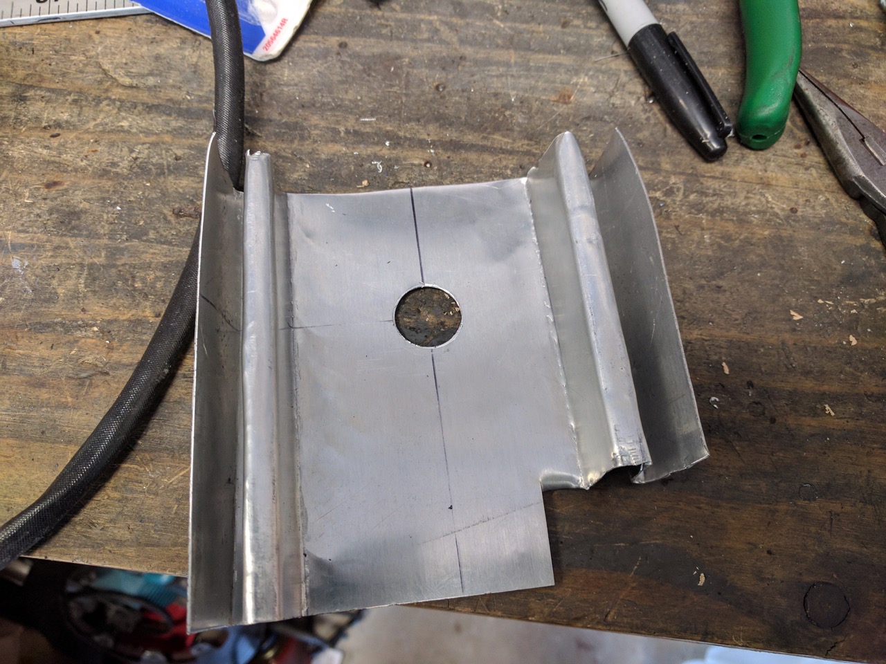
So at the last few track days the wideband has been pegging at 22:1 about halfway through the second session. It fixes itself once it cools all the way down at home, and seems to work properly after that, but clearly this isn't good. I've got a replacement sensor, but rather than put it in and do the same thing to it I wanted to try to fix the problem first.

So, one piece of aluminum sheet metal and some bending in the vise:


Of course, then I took the car out for a drive and it started spewing sync errors and shutting off once it went into boost. I had the wiring apart last week trying to reverse-engineer the serial protocol going to the racelogic TC unit, and must have screwed something up. Doh.

--Ian
Old May 16, 2017 | 05:40 PM
  #913  
JasonC SBB's Avatar
Elite Member
 
Joined: Jul 2005
Posts: 6,420
Total Cats: 84
Default

I suggest putting some kind of insulating washer between your heatsink and the exhaust pipe. Maybe a thick stainless steel washer?
Old May 16, 2017 | 08:12 PM
  #914  
EO2K's Avatar
Elite Member
iTrader: (37)
 
Joined: Apr 2010
Posts: 10,477
Total Cats: 1,924
From: Very NorCal
Default

You mean, other than the big wrinkly piece of metal in the picture?
Old May 19, 2017 | 05:15 PM
  #915  
codrus's Avatar
Thread Starter
Elite Member
 
Joined: Mar 2007
Posts: 5,298
Total Cats: 884
From: Santa Clara, CA
Default

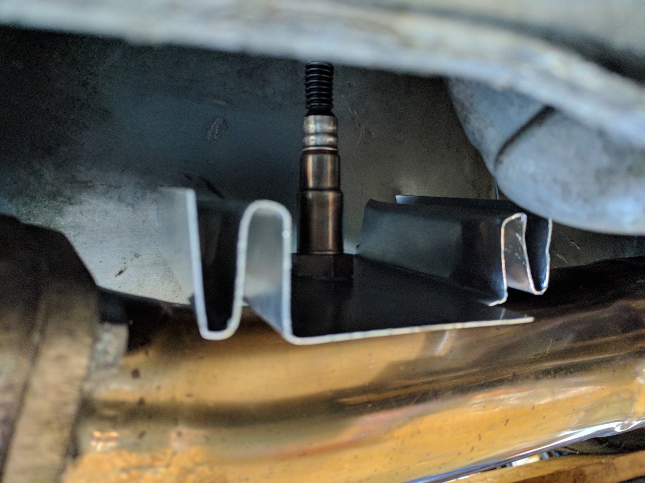
I think Jason is suggesting trying to insulate the heat sink from the exhaust itself, so that it works more effectively at cooling the sensor.

I dunno what good a stainless washer would do, though, since the whole exhaust is stainless.

I have also heard that these kinds of sheet metal "heat sinks" are actually more effective as radiant heat shields. I dunno, we'll see how it does at the track next week.

--Ian
Old May 19, 2017 | 05:29 PM
  #916  
Art's Avatar
Art
Junior Member
 
Joined: Jul 2016
Posts: 369
Total Cats: -251
Default

.

Last edited by Art; Jun 11, 2018 at 07:41 PM.
Old May 19, 2017 | 05:35 PM
  #917  
18psi's Avatar
VladiTuned
iTrader: (76)
 
Joined: Apr 2008
Posts: 35,821
Total Cats: 3,482
Default

Originally Posted by Art
O2 sensor horizontal instead of vertical might help with heat but can't tell from the pic. .
this actually sounds like a really good idea.
fm dp mounts it at the very top iirc, the hottest spot (but least likely to get damaged)
Old May 19, 2017 | 05:54 PM
  #918  
codrus's Avatar
Thread Starter
Elite Member
 
Joined: Mar 2007
Posts: 5,298
Total Cats: 884
From: Santa Clara, CA
Default

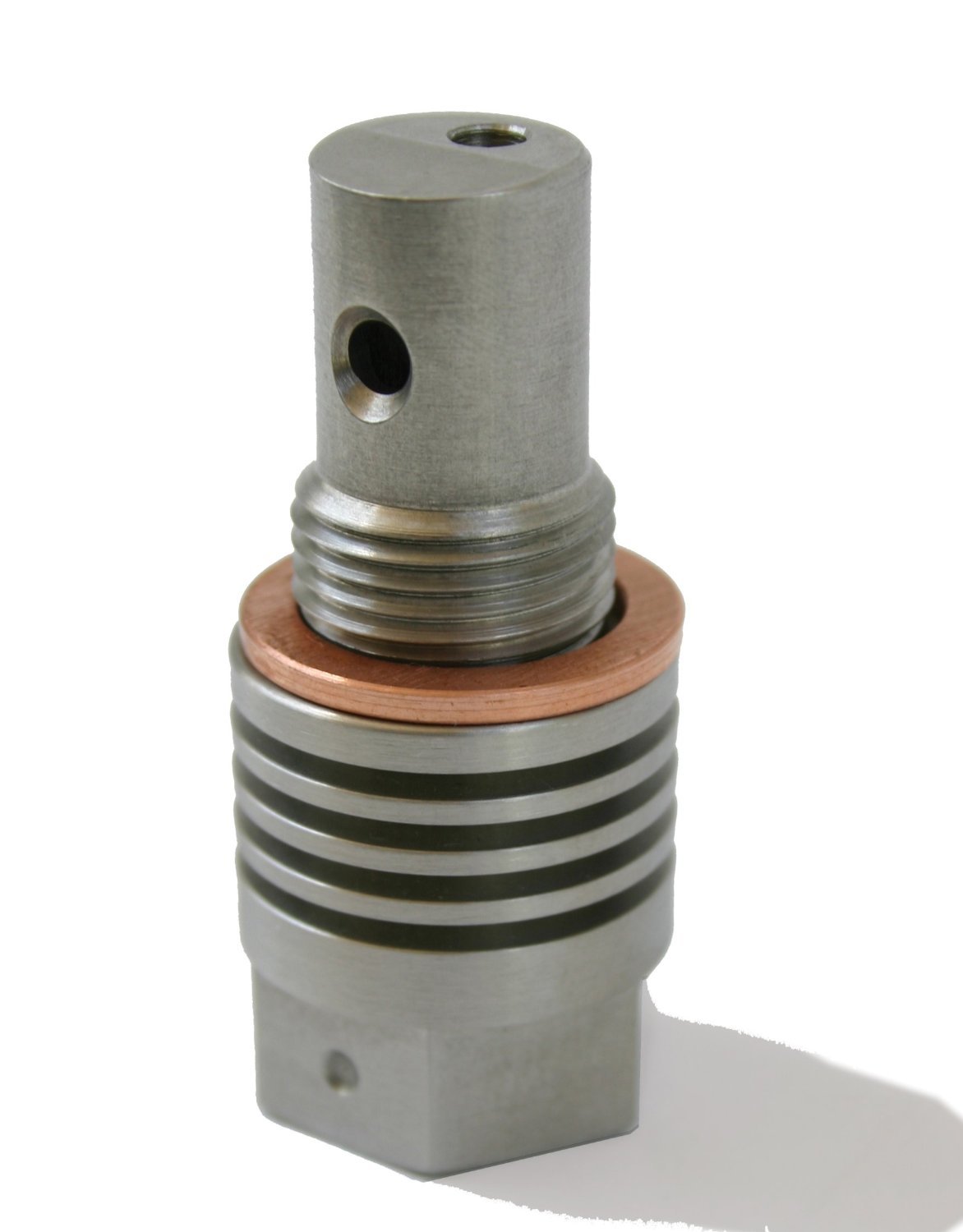
Yes, the FM downpipe points it straight up. It could probably lean over 20 degrees or so, but I don't think there's room to mount it horizontally. The LC-2 instructions say it should be between 9 and 3 o'clock.

Apparently Innovate sells this guy too:


Amazon Amazon

$65 -- I may try that if the heat sink/shield doesn't help.

--Ian
Old May 19, 2017 | 07:01 PM
  #919  
EO2K's Avatar
Elite Member
iTrader: (37)
 
Joined: Apr 2010
Posts: 10,477
Total Cats: 1,924
From: Very NorCal
Default

Would that not cut down on the flow of gas to the sensor itself? Possibly slowing down the readings?

FWIW I've got an 1/16" thick piece of brass about the size of compact disc with a hole in the middle the perfect size for an O2 sensor. Gesso had it in his random box of scrap so I tossed it on when we did my exhaust and its been there ever since.
Old May 19, 2017 | 07:12 PM
  #920  
codrus's Avatar
Thread Starter
Elite Member
 
Joined: Mar 2007
Posts: 5,298
Total Cats: 884
From: Santa Clara, CA
Default

Originally Posted by EO2K
Would that not cut down on the flow of gas to the sensor itself? Possibly slowing down the readings?
Well, Innovate makes it, so I assume it works with their sensors. It's got holes in specific locations and needs to be indexed a particular way.

--Ian

Thread Tools
Search this Thread

All times are GMT -4. The time now is 08:11 AM.