Ian's 99 build thread

Thread Starter
Elite Member

Joined: Mar 2007
Posts: 5,306
Total Cats: 887
From: Santa Clara, CA

--Ian
Reply
 0
0

0
Thread Starter
Elite Member
Joined: Mar 2007
Posts: 5,306
Total Cats: 887
From: Santa Clara, CA
After building the new filter circuit last weekend I got the flu (argh, I am so tired of being sick this year!). Down for most of a week, although during that time some trubokitty stickers arrived!
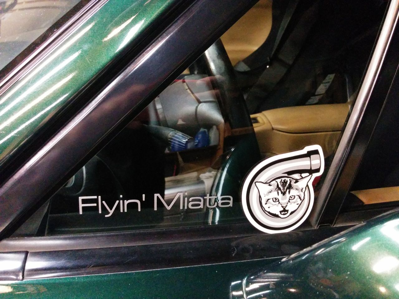
(not actually stuck on the window yet -- haven't quite decided if that's where I want to put it yet).
Anyhow, we went out and tested the filter circuit with some sustained driving today. Put 90 miles on it, (total of 120 on the motor so far) and with zero anomalous sync errors (just the sort-of expected ones when the motor stalls/etc). It's not definitive yet, but that's a very encouraging sign, I'm not sure the MS3 has ever gone that far without a random sync error before.
So while driving around we did some boost control tuning. Oh my god, tuning EBC with the external wastegate is SO MUCH EASIER than it was with the IWG. The MS3 boost control on the 2560 IWG was just about hopeless, the best I was ever able to get was to a slow rise to target followed by a dip with a slow rise back. With the EWG, on the other hand, we just threw in some conservative PID values (10/10/0, I think), took a random guess at the other settings, and it was 90% of the way there. A nice rise to target with a small spike that was easily tuned out by adjusting the delta value for enabling boost control.
The 2863 is definitely soggier on the boost response than the 2560 was. The 2560 would hit full boost around 3400 rpm in 4th/5th, the 2863 isn't doing it til almost 3800. I didn't expect the same kind of response, but this is a bit more of a step down than I'd hoped for. Ah well, it's not fully tuned yet -- needs dyno time to set the timing and the adjustable cam gear for the intake is just sitting at a random middle-ish location.
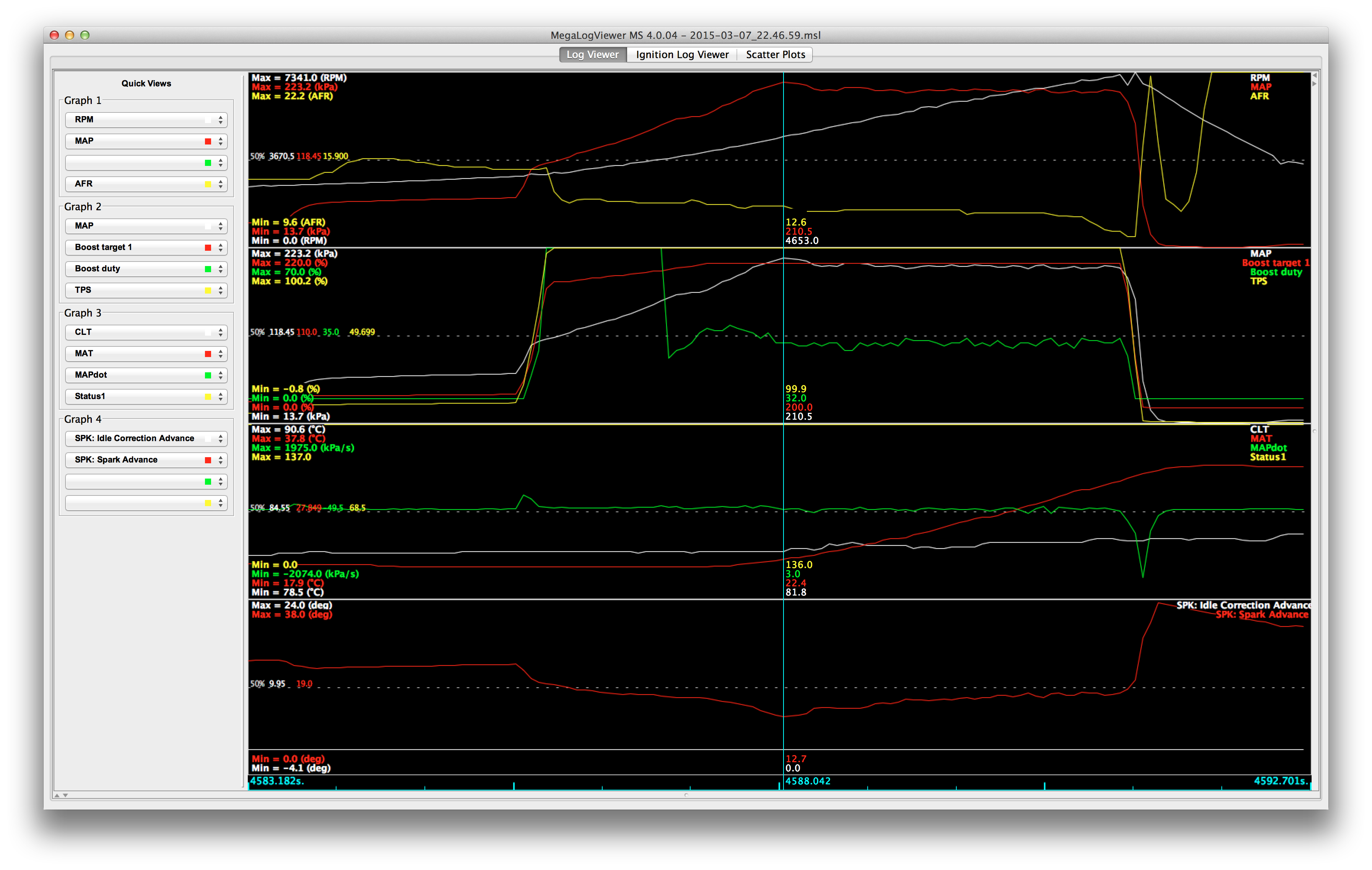
Did some datalogging of a 220 kpa run:
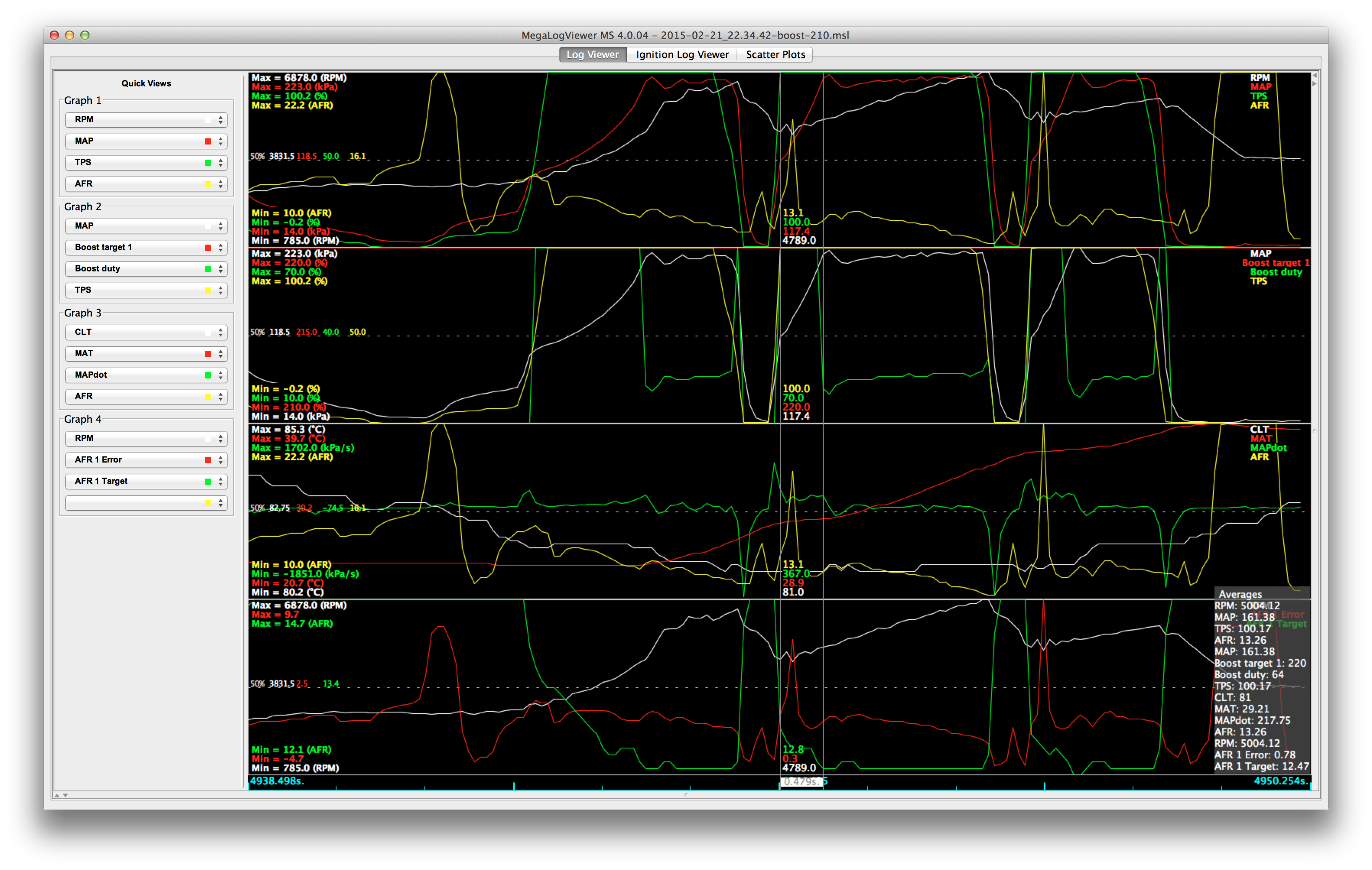
It's taking almost half a second to get back to full boost after shifting. This is about twice as long as it did with the 2560 -- I'm wondering if the bypass/blowoff valve is working as well as it should because I'm also getting a chirpy noise on shifting. It doesn't *quite* sound like compressor stall, but...
Another random observation is that this turbo is much quieter than the old one. It doesn't have the giant sucking sound from the intake -- perhaps the anti-reservsion inlet on the 2863 quiets that down? I dunno.
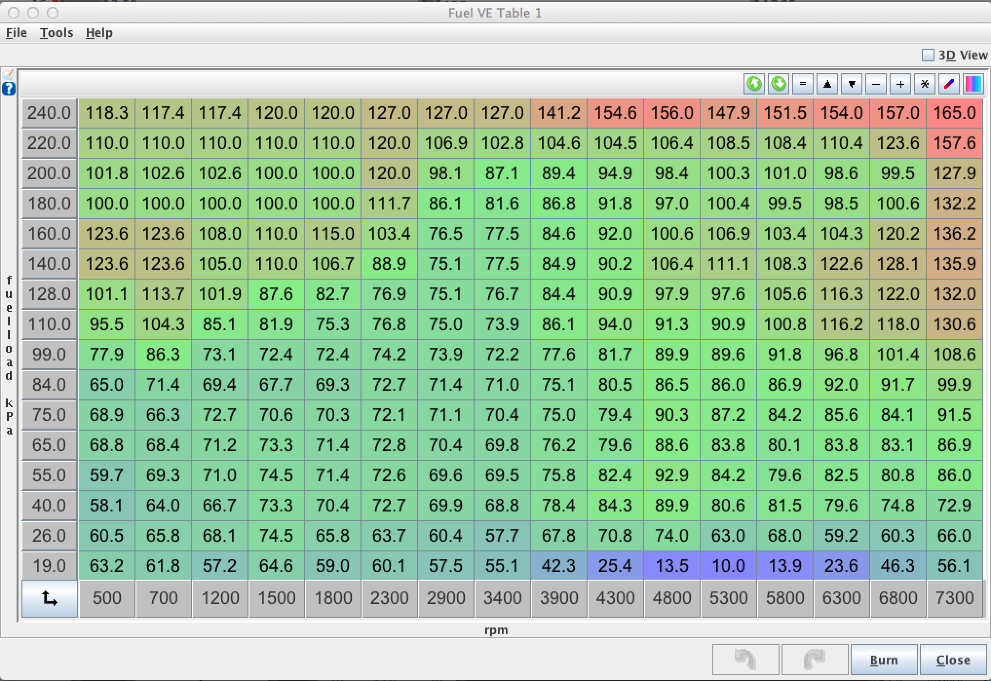
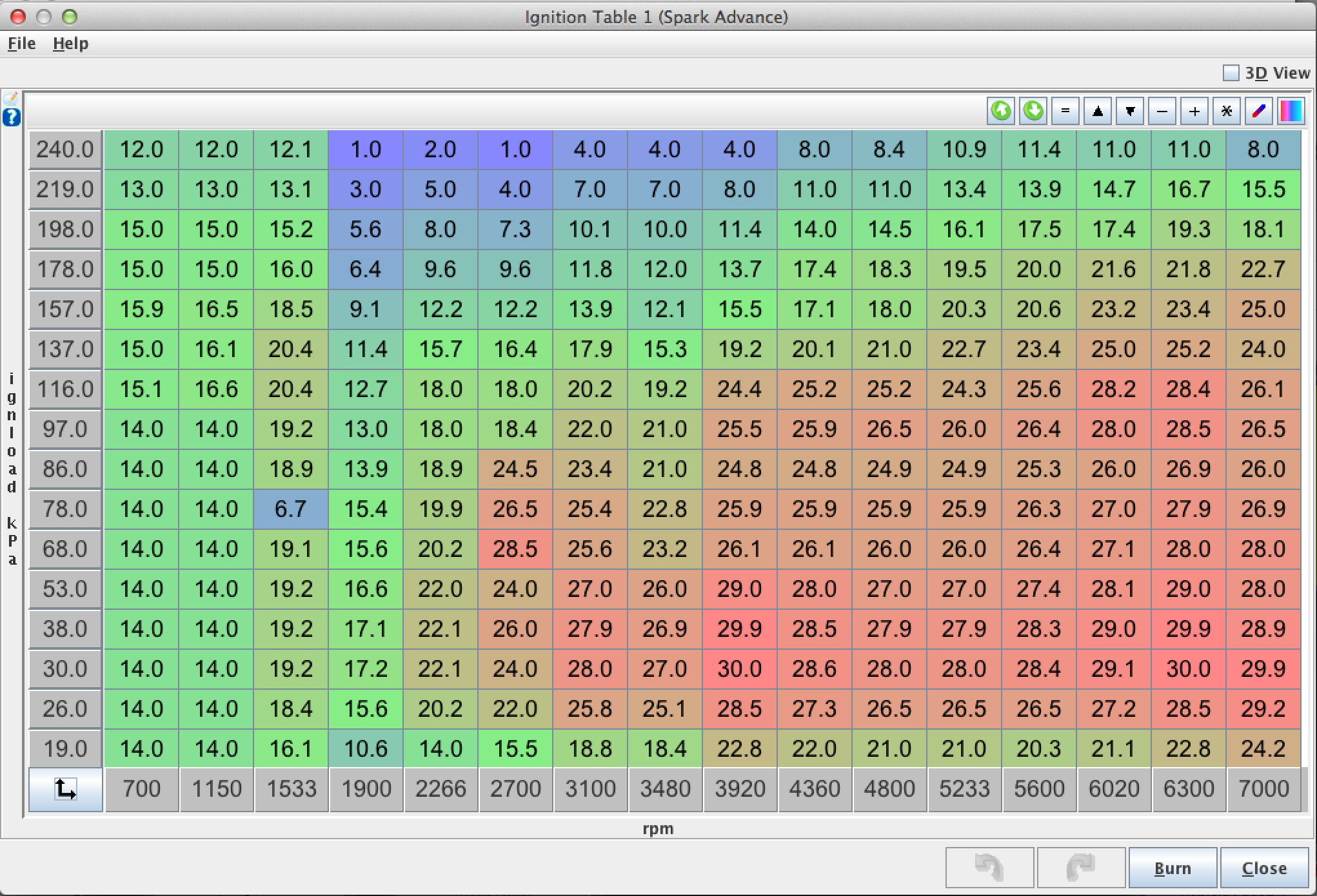
Random screen grabs from TS. The fuel isn't too bad, but the spark table is the wrong shape and needs a trip to the dyno. (If the advance seems aggressive, it's because I run 95 octane in the car).
It's running well enough now that I think I can risk driving it to work to put some miles on it. Once I get it up to 250 or so, I'll change the oil again and go dyno tuning.
--Ian
(not actually stuck on the window yet -- haven't quite decided if that's where I want to put it yet).
Anyhow, we went out and tested the filter circuit with some sustained driving today. Put 90 miles on it, (total of 120 on the motor so far) and with zero anomalous sync errors (just the sort-of expected ones when the motor stalls/etc). It's not definitive yet, but that's a very encouraging sign, I'm not sure the MS3 has ever gone that far without a random sync error before.
So while driving around we did some boost control tuning. Oh my god, tuning EBC with the external wastegate is SO MUCH EASIER than it was with the IWG. The MS3 boost control on the 2560 IWG was just about hopeless, the best I was ever able to get was to a slow rise to target followed by a dip with a slow rise back. With the EWG, on the other hand, we just threw in some conservative PID values (10/10/0, I think), took a random guess at the other settings, and it was 90% of the way there. A nice rise to target with a small spike that was easily tuned out by adjusting the delta value for enabling boost control.
The 2863 is definitely soggier on the boost response than the 2560 was. The 2560 would hit full boost around 3400 rpm in 4th/5th, the 2863 isn't doing it til almost 3800. I didn't expect the same kind of response, but this is a bit more of a step down than I'd hoped for. Ah well, it's not fully tuned yet -- needs dyno time to set the timing and the adjustable cam gear for the intake is just sitting at a random middle-ish location.
Did some datalogging of a 220 kpa run:
It's taking almost half a second to get back to full boost after shifting. This is about twice as long as it did with the 2560 -- I'm wondering if the bypass/blowoff valve is working as well as it should because I'm also getting a chirpy noise on shifting. It doesn't *quite* sound like compressor stall, but...
Another random observation is that this turbo is much quieter than the old one. It doesn't have the giant sucking sound from the intake -- perhaps the anti-reservsion inlet on the 2863 quiets that down? I dunno.
Random screen grabs from TS. The fuel isn't too bad, but the spark table is the wrong shape and needs a trip to the dyno. (If the advance seems aggressive, it's because I run 95 octane in the car).
It's running well enough now that I think I can risk driving it to work to put some miles on it. Once I get it up to 250 or so, I'll change the oil again and go dyno tuning.
--Ian
Reply
0
0
Thread Starter
Elite Member
Joined: Mar 2007
Posts: 5,306
Total Cats: 887
From: Santa Clara, CA
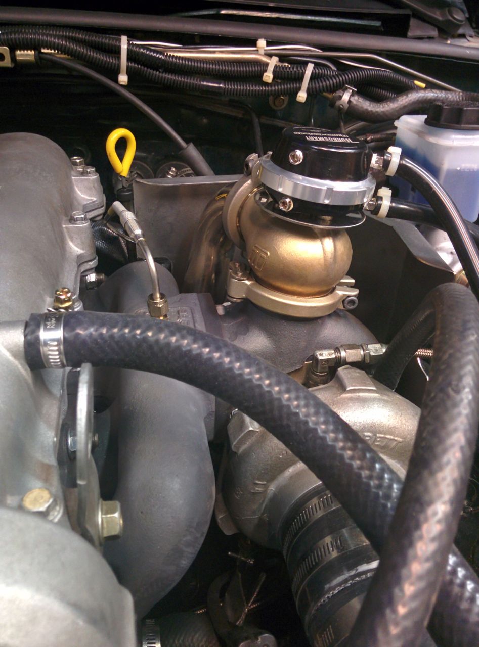
One random other shot from today -- the EWG is turning gold.
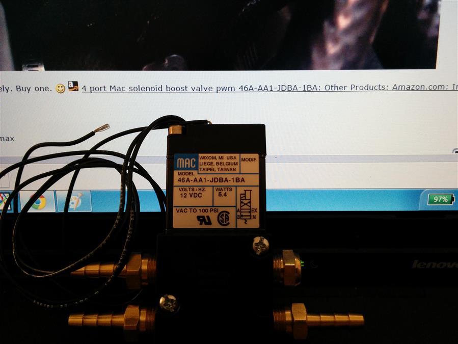
Also, E02K: This solenoid works nicely. Buy one.
--Ian
Also, E02K: This solenoid works nicely. Buy one.
--Ian
Reply
0
0


Newb
Joined: Sep 2014
Posts: 21
Total Cats: 5
The optoisolators are very nonlinear. The input-to-output looks like this:
Or if you look at it as a transfer ratio, it's something like this:
In other words: it's dead at the bottom; then has a window of high gain as it switches on; then it saturates and the gain becomes relatively low again.
The MS input looks like this: CKP === Opto === RC low-pass === Schmitt input on MCU
My theory is the problem happens when if you get some noise just when the optoisolators are switching on. There's no filter on their input side, so they receive the raw noise, amplify it (since they're in the high-gain region), and pass it on. If the amplified noise becomes larger than the Schmitt trigger hysteresis it can cause double triggers.
Oh my god, tuning EBC with the external wastegate is SO MUCH EASIER than it was with the IWG.
Regardless, the whole package is much easier to control. After setting some rough min and max duty values on the new solenoid we did some highway pulls. The Basic tuning mode still sucks, but after switching to Advanced mode it took less than ten minutes to have it running better than the old setup ever did.
Reply
0
0
Thread Starter
Elite Member
Joined: Mar 2007
Posts: 5,306
Total Cats: 887
From: Santa Clara, CA
Nothing much interesting happening with the Miata. I've driven it around some (150 miles on the motor now), and done some tuning, but there's nothing visual. Still trying to nail down dyno time to tune it properly.
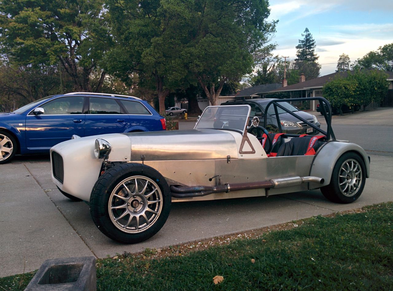
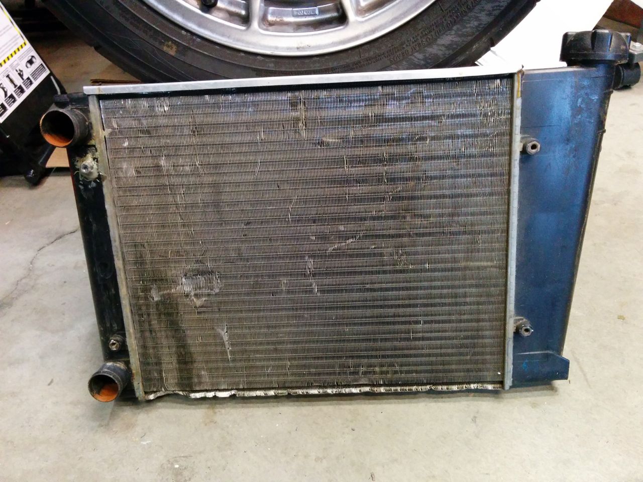
So I did some work on the Seven this weekend instead. The guy who built it did a few things that I find somewhat questionable, and I'm slowly working on fixing those. The fuel system was a nightmare (mostly fixed now by replacing literally every component except the tank, the pump, and the injectors), but the cooling system had some issues as well. Sevens have a narrow nose, so most conventional car radiators don't fit. There are a few standard car radiators that are about the right size, the builder had used one that I think is out of an early-80s BMW of some kind.
The core is roughly 15 inches square, with plastic side tanks, and it's a dual-pass because both hose ports are on the same side. There are a few problems with it -- it's very beat-up and he appears to have mounted it to the chassis using the fan bolts. One of the threaded holes had stripped and has an epoxied-on nut to repair it. Worst of all, the fill cap leaks and appears to have been RTV-ed on in an attempt to fix the leak.
Since I'm not totally sure what car this rad came from and don't feel like spending hours scouring junkyards looking for one, I decided to go with one from an early-90s Honda Civic. They're dirt cheap, I picked up an aluminum one from Amazon Prime (free shipping!) for $50.
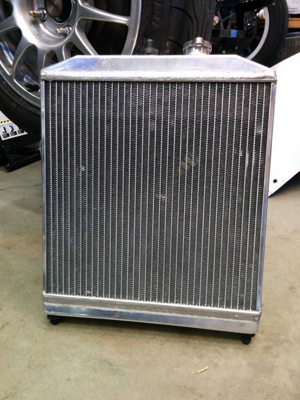
(The bent fins are from stupidly taking the cardboard off before test-fitting it. They were straight when it arrived)
Not sure if the fan he used was from the donor Miata or not, but it fits the Civic rad nicely.
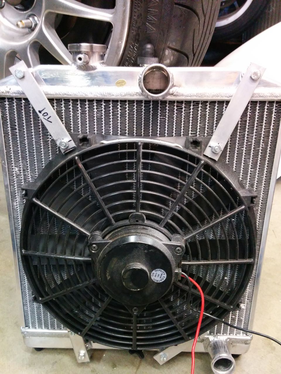
The Civic radiator uses post mounts like the Miata, and needs mounting bushings. I didn't have any extra of those, and nobody keeps them in stock. I did find a few generic "donut" bushings, and combining those with a large rubber vacuum cap made for a workable bushing.
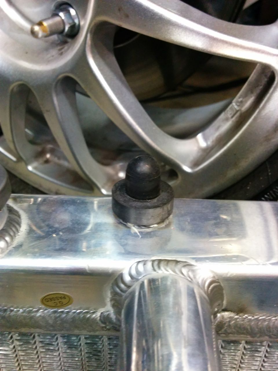
The core is about the same size, but it's top/bottom tank so it's taller and narrower than the BMW (?) one. The lower hose outlet wants to occupy the same space as the steering rack mount, so to clear that and also fit inside the nose it needs to be angled slightly.
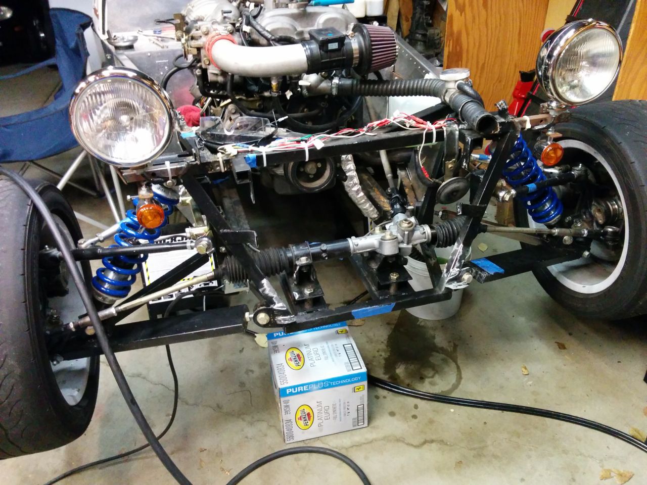
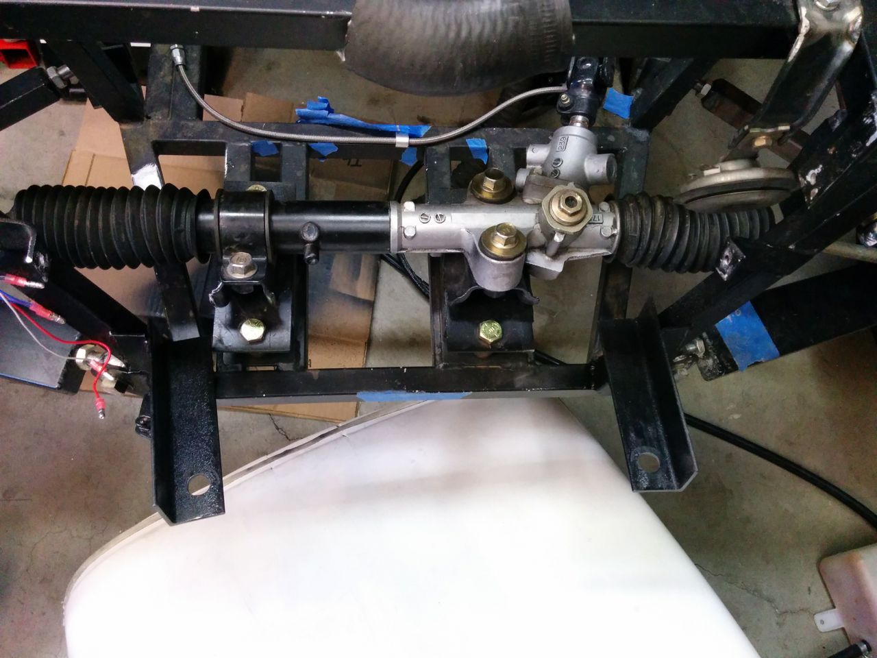
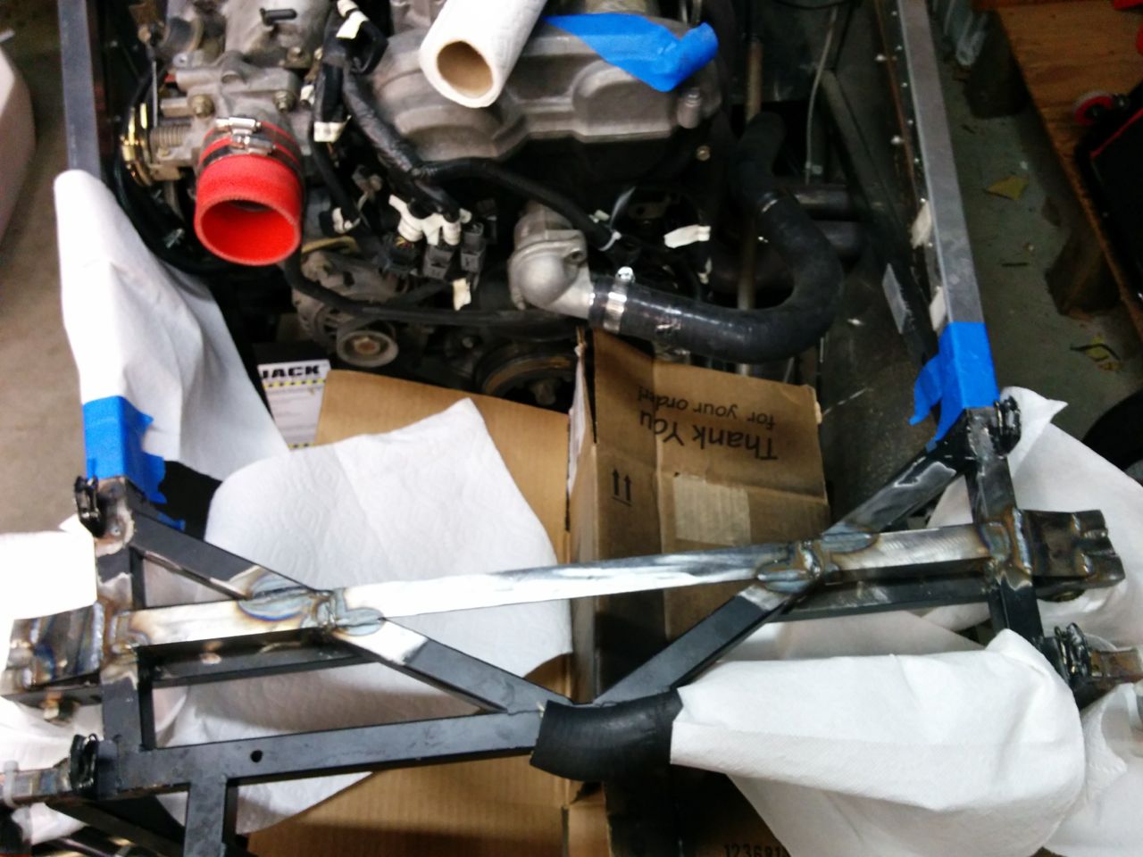
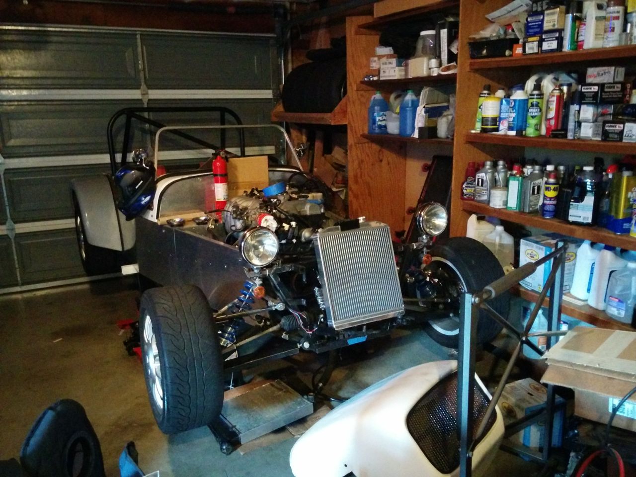
So, tear the front of the car down and we've got this. Yes, the wiring at the front is a huge tangled mess -- cleaning that up is on the list of Seven-related projects.
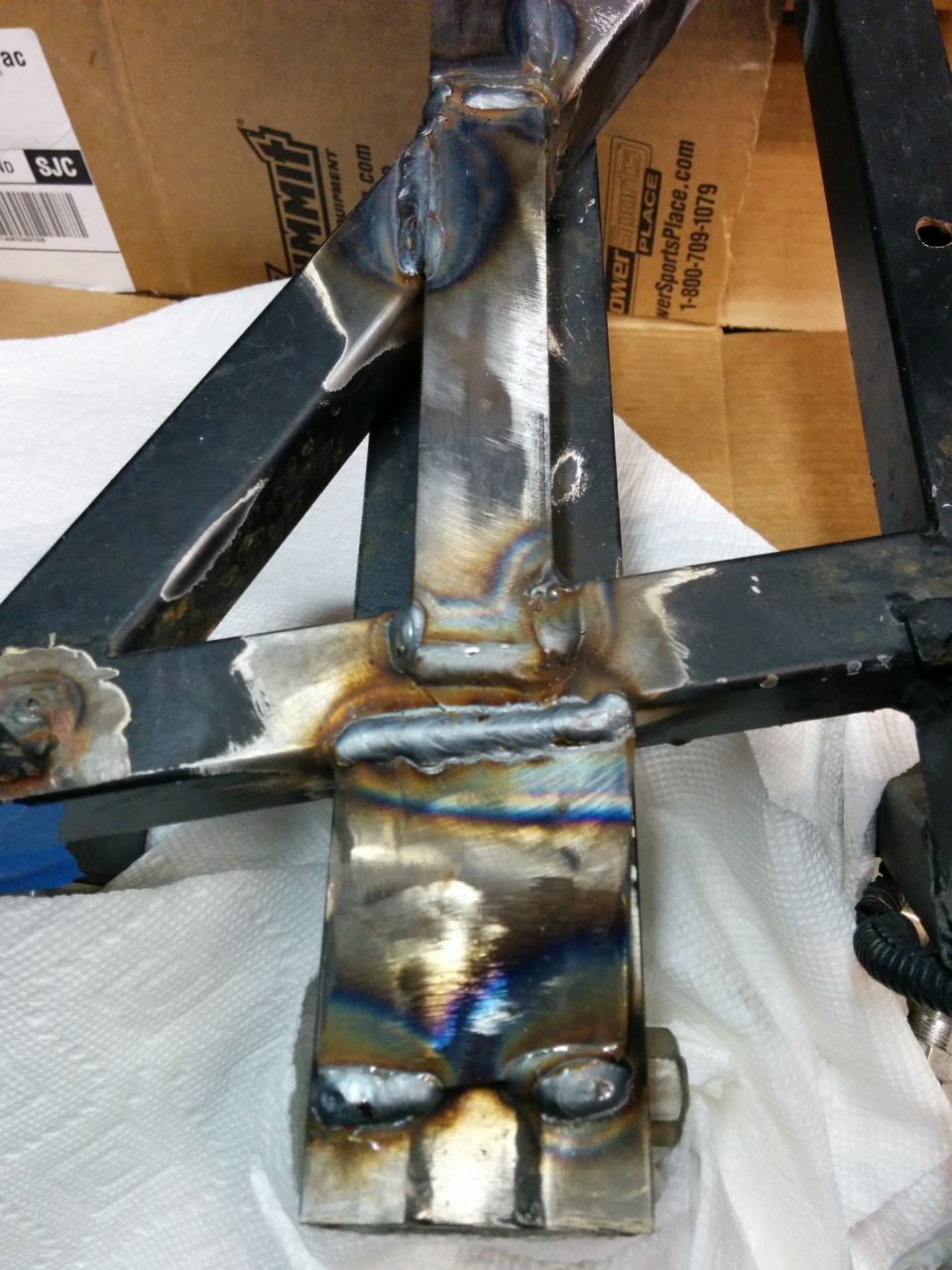
Some 1" angle iron welded on with holes in the bottom for the bushings. My welding still sucks.
And the bottom mount mounts are done! If the brackets look like they're mounted at different angles then that's because they are, but it's what's required to center the rad in the chassis. I'm not sure if that's because the chassis isn't symmetric (well, I know it's not, but I don't know if it's off that badly) or if the two bottom posts on the rad are in different locations.
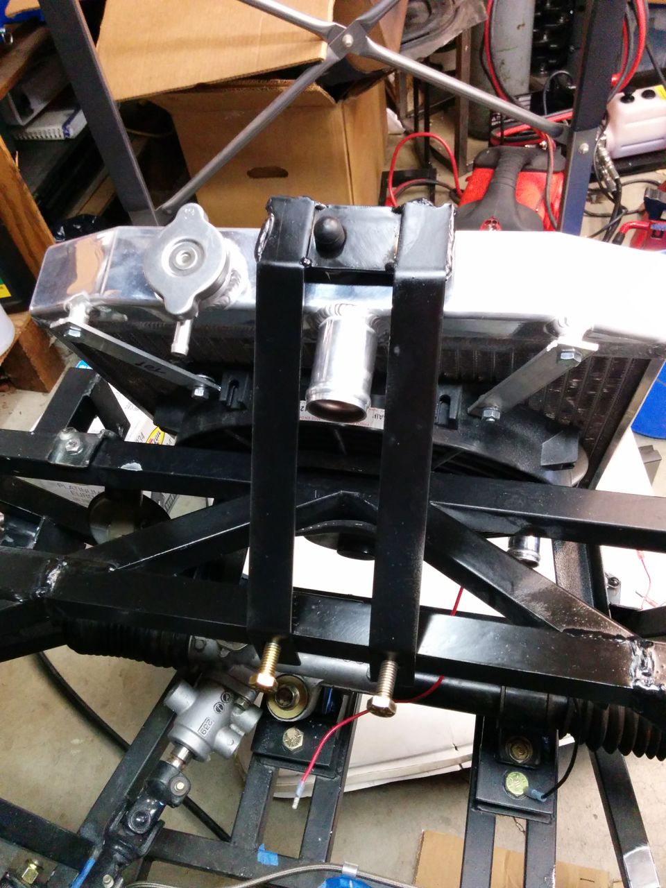
The top mount is trickier, because there's no structure that high in the front of the nose to attach it to. So I added a piece of angle across the nose:
It's amazing how much ugliness can you can hide by painting the welds black.
And then a massively-overengineered top bracket. More angle, a couple of bent pieces of flat, and some holes with welded nuts on the cross-angle:
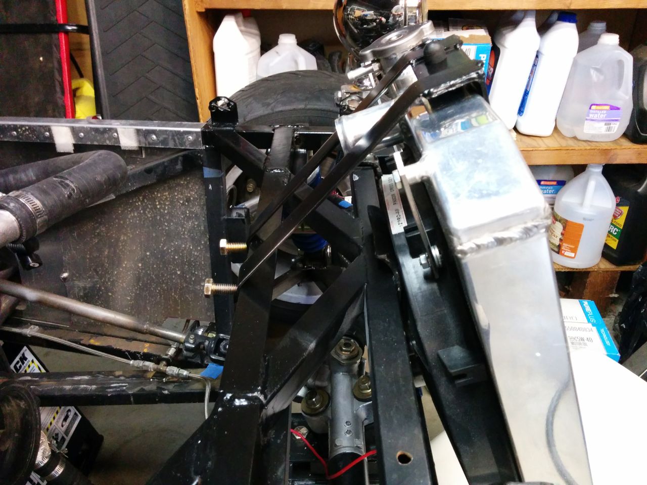
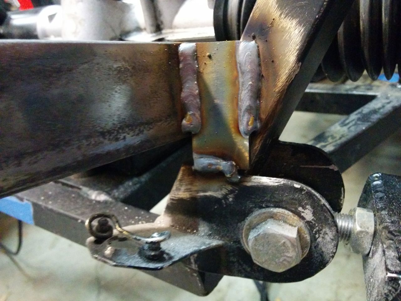
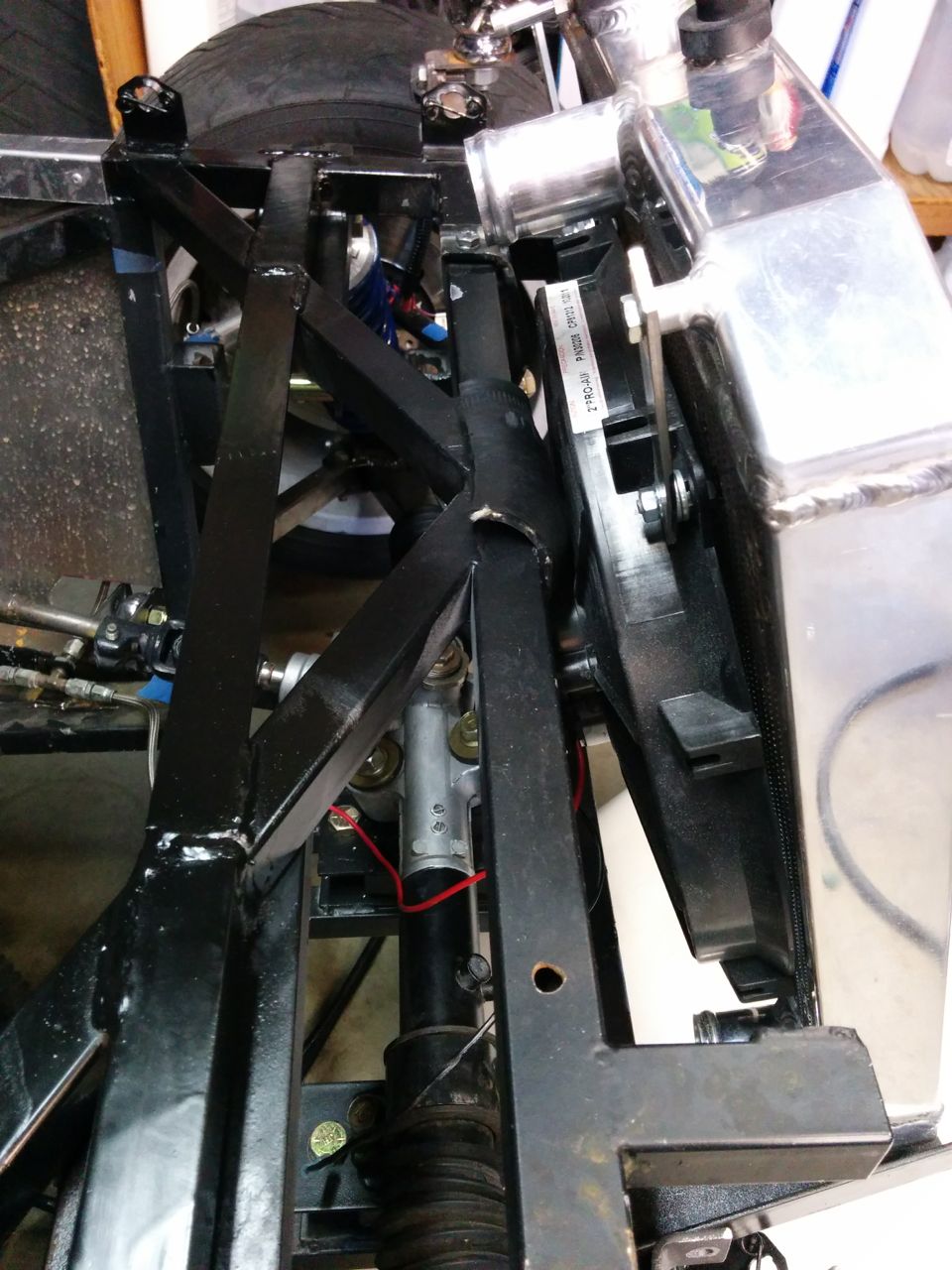
Another problem with the car is that the front suspension upper mounts are kind of stuck out into space, cantilevered using a couple of pieces of small angle iron:
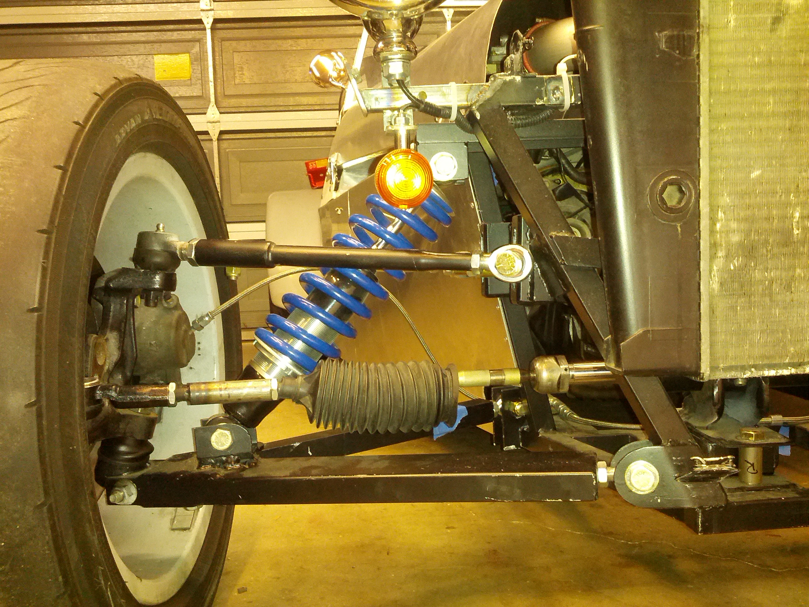
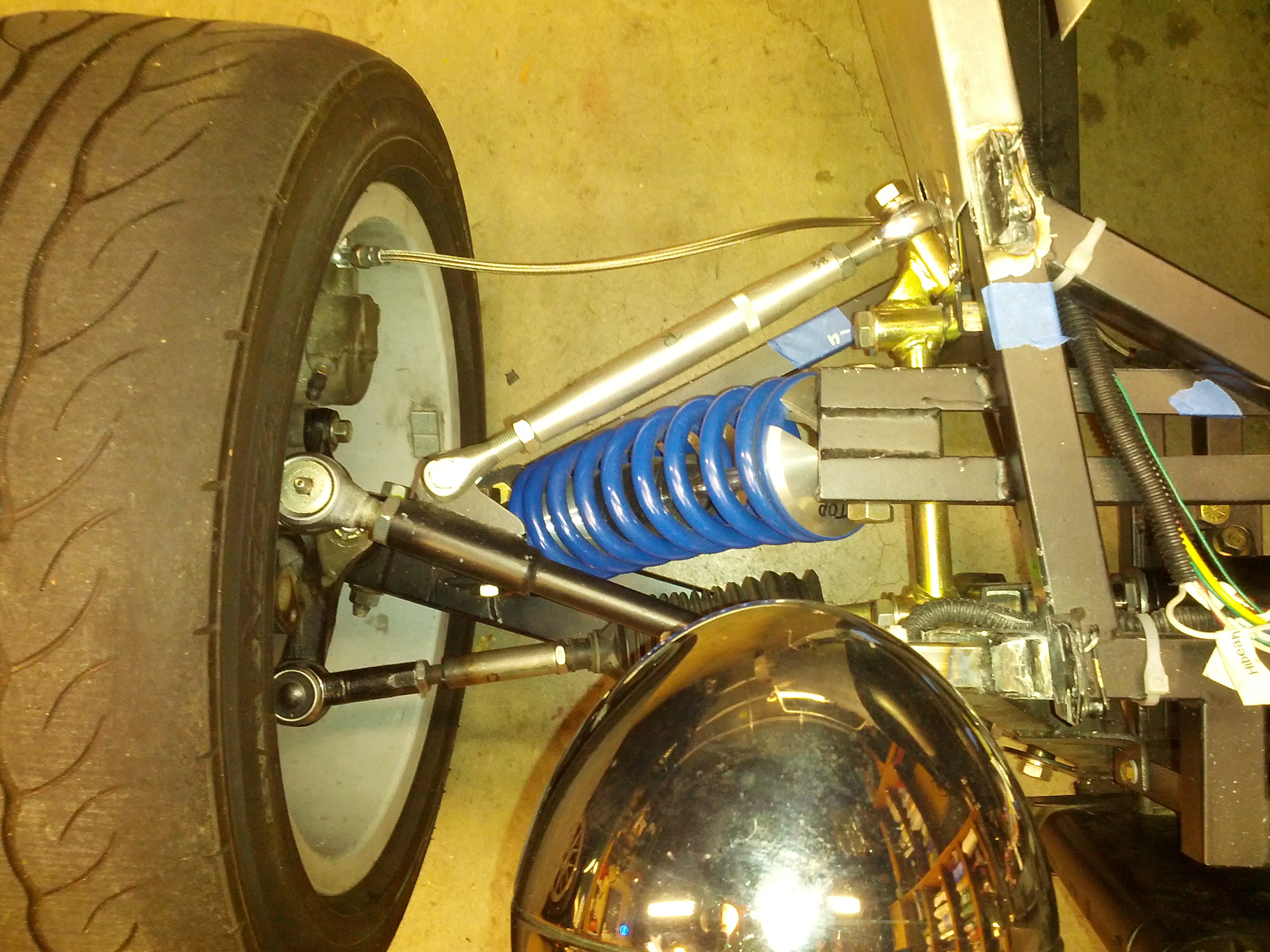
TurboKitten simulated this in solidworks and it looks marginal on strength. Fortunately, it's pretty simple to reinforce. Another piece of angle connecting the main side rail with one of the diagonal tubes on the nose, and a triangulation piece for the top mount bracket itself:
The original builder had put in generic corrugated hose top and bottom, which wind up in the wrong locations for the new radiator. For the bottom, an old Miata lower radiator hose, trimmed at both ends does a good job of connecting to the corrugated hose. For the top, I had a silicone Miata lower radiator hose lying around. FM makes these, they're supposed to improve clearance around the intercooler tubes. It never really fit in my car, so it just sat on the shelf, but it's damn near a perfect fit as an upper hose on the Seven.
So the mechanical bits are all done and it fits in the car. Now I just need to find a coupler for the bottom hose and then fill it with coolant and see how badly a $50 radiator leaks.
--Ian
So I did some work on the Seven this weekend instead. The guy who built it did a few things that I find somewhat questionable, and I'm slowly working on fixing those. The fuel system was a nightmare (mostly fixed now by replacing literally every component except the tank, the pump, and the injectors), but the cooling system had some issues as well. Sevens have a narrow nose, so most conventional car radiators don't fit. There are a few standard car radiators that are about the right size, the builder had used one that I think is out of an early-80s BMW of some kind.
The core is roughly 15 inches square, with plastic side tanks, and it's a dual-pass because both hose ports are on the same side. There are a few problems with it -- it's very beat-up and he appears to have mounted it to the chassis using the fan bolts. One of the threaded holes had stripped and has an epoxied-on nut to repair it. Worst of all, the fill cap leaks and appears to have been RTV-ed on in an attempt to fix the leak.
Since I'm not totally sure what car this rad came from and don't feel like spending hours scouring junkyards looking for one, I decided to go with one from an early-90s Honda Civic. They're dirt cheap, I picked up an aluminum one from Amazon Prime (free shipping!) for $50.
(The bent fins are from stupidly taking the cardboard off before test-fitting it. They were straight when it arrived)
Not sure if the fan he used was from the donor Miata or not, but it fits the Civic rad nicely.
The Civic radiator uses post mounts like the Miata, and needs mounting bushings. I didn't have any extra of those, and nobody keeps them in stock. I did find a few generic "donut" bushings, and combining those with a large rubber vacuum cap made for a workable bushing.
The core is about the same size, but it's top/bottom tank so it's taller and narrower than the BMW (?) one. The lower hose outlet wants to occupy the same space as the steering rack mount, so to clear that and also fit inside the nose it needs to be angled slightly.
So, tear the front of the car down and we've got this. Yes, the wiring at the front is a huge tangled mess -- cleaning that up is on the list of Seven-related projects.
Some 1" angle iron welded on with holes in the bottom for the bushings. My welding still sucks.
And the bottom mount mounts are done! If the brackets look like they're mounted at different angles then that's because they are, but it's what's required to center the rad in the chassis. I'm not sure if that's because the chassis isn't symmetric (well, I know it's not, but I don't know if it's off that badly) or if the two bottom posts on the rad are in different locations.
The top mount is trickier, because there's no structure that high in the front of the nose to attach it to. So I added a piece of angle across the nose:
It's amazing how much ugliness can you can hide by painting the welds black.
And then a massively-overengineered top bracket. More angle, a couple of bent pieces of flat, and some holes with welded nuts on the cross-angle:
Another problem with the car is that the front suspension upper mounts are kind of stuck out into space, cantilevered using a couple of pieces of small angle iron:
TurboKitten simulated this in solidworks and it looks marginal on strength. Fortunately, it's pretty simple to reinforce. Another piece of angle connecting the main side rail with one of the diagonal tubes on the nose, and a triangulation piece for the top mount bracket itself:
The original builder had put in generic corrugated hose top and bottom, which wind up in the wrong locations for the new radiator. For the bottom, an old Miata lower radiator hose, trimmed at both ends does a good job of connecting to the corrugated hose. For the top, I had a silicone Miata lower radiator hose lying around. FM makes these, they're supposed to improve clearance around the intercooler tubes. It never really fit in my car, so it just sat on the shelf, but it's damn near a perfect fit as an upper hose on the Seven.
So the mechanical bits are all done and it fits in the car. Now I just need to find a coupler for the bottom hose and then fill it with coolant and see how badly a $50 radiator leaks.
--Ian
Reply
0
0

Thread Starter
Elite Member
Joined: Mar 2007
Posts: 5,306
Total Cats: 887
From: Santa Clara, CA
There's a BP6D in the background in many of those shots! Plus a Miata 6-speed, 3.9 Torsen, halfshafts, uprights, hubs, brakes, wheels, factory '01 computer, hacked-up wiring harness, fuel pump, and, uh... OK, I guess that's about it. Like an Exocet but without the subframes or the A-arms.
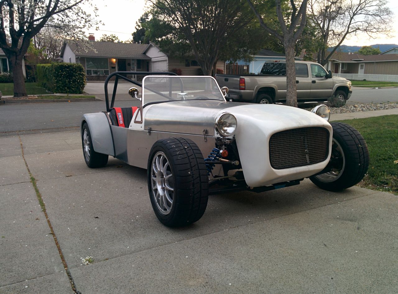
And yeah, I was noticing the "hot rod" look as well. I'm not particularly fond of it, so the nose will be going back on as soon as I've got the system bled.
--Ian
And yeah, I was noticing the "hot rod" look as well. I'm not particularly fond of it, so the nose will be going back on as soon as I've got the system bled.
--Ian
Reply
0
0
Thread Starter
Elite Member
Joined: Mar 2007
Posts: 5,306
Total Cats: 887
From: Santa Clara, CA
So this weekend I worked on finishing up the Seven's radiator. Got it plumbed in and the wiring up front all cleaned up, but alas the generic aftermarket coolant expansion tank I had bought turns out to leak, so I didn't get to start it. Argh. I gooped it up with RTV, we'll see if that holds. Probably not.
On to the Miata. My goal is to run TPS-based boost control, ranging from ~150 to 220 kpa between about ~ 50 to 100% throttle. Since my current wastegate setup makes 180 kpa, I needed to do something about that. Also, I plan to dyno it in the near future and need stable boost control at varying levels for that. So, since I have an EWG, you're supposed to be able to adjust the spring pressure in it. First step is to take it off the car and put it in a vise (man the v-bands make this so much easier). The vise is a spring compressor, apparently there's quite a bit of pressure there.
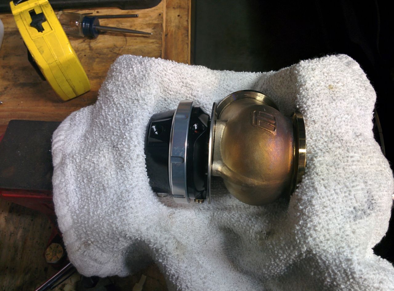
(Note, if you're doing this, make sure the vise opens wide enough to get it all the way apart. Mine did, but only afer I blew through the washer & cotter pin that were supposed to stop it from going wider. Oops.)
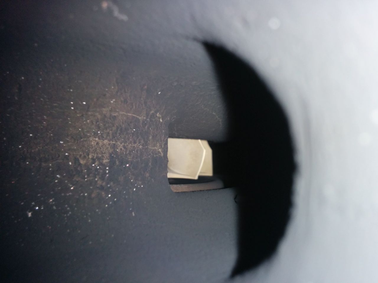
If you take the EWG off, you can see the turbine wheel through the hole! Whee!
Then admire the springs inside it. Mine has two, which are apparently both nominally 7 psi and should thus deliver 14 psi of boost. I get 12. Whatever.
TurboSmart identifies their springs with colored paint codes instead of numbers, for some stupid reason. One of mine had beige paint on it, instead of the red or blue or whatever it was supposed to be. Fortunately they also publish diameters and free lengths, so this didn't matter.
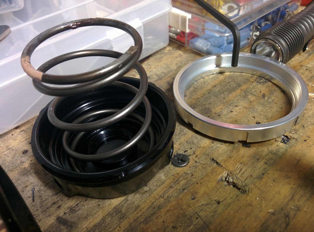
The TS instructions say it's OK to run one spring, so I removed the small one and just used the large one.
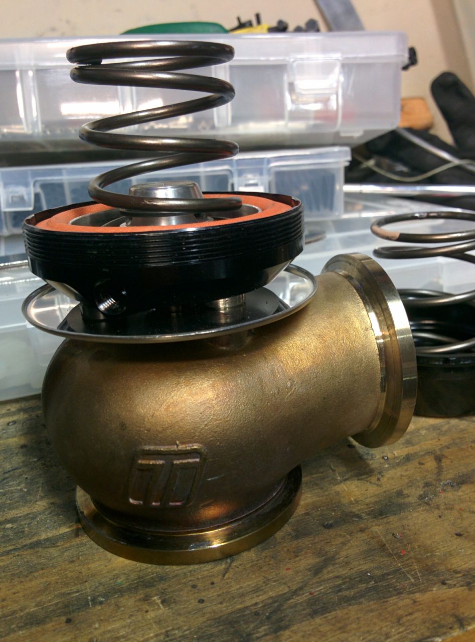
This turns out to deliver 6 psi of boost (which makes sense, if the two springs are the same and both deliver 6, that makes 12 which is what I saw before). 140 kpa, that's great. So we took the car out and tuned it at various boost levels, setting up the TPS table and initial duty cycle table. Works great. Man, this 2863 with EWG is so much easier to control than the 2560 ever was. A couple hours of driving around adjusting the PID values, setting up the initial duty table and the TPS targets and it's working really nicely.
Last summer when I first put the MS3 in the case, I tried to port over the timing numbers from the Hydra. Unfortunately the Hydra (2.5 at least) doesn't appear to have spark latency compensation in it, so the timing numbers from it are massively advanced compared to what the MS3 uses. It was so bad that when I ran that map on the dyno last May (with the 2560), some cells were 10 degrees past MBT. Have I mentioned I love using 50% race gas? It didn't ping, even with those stupid timing numbers in it. Anyway, that dyno session *also* turned out to be totally screwed up becasue the cat had failed, and the resulting timing map was a mess. So I reverted back to the timing map that was in the MS3 when I got it from Reverant. Very conservative numbers compared to what I had been using, which the EGT gauge made obvious, but I'll fix them on the dyno.
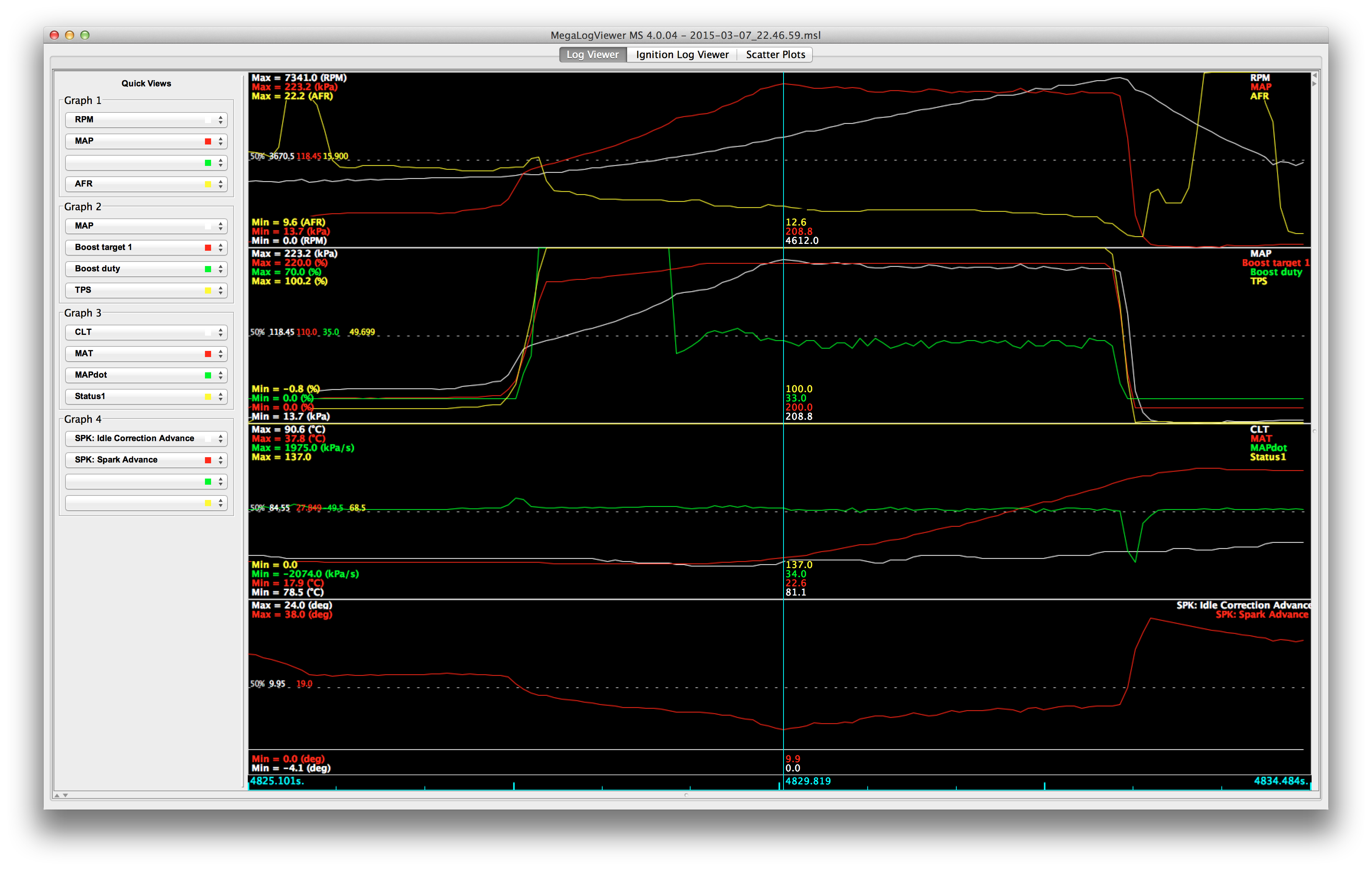
One of the annoying things about tuning a turbo on the dyno is that when you adjust the timing, a poor boost control algorithm with sometimes result in a different MAP value. This makes it difficult to find MBT because you can't tell if you gained power because of the timing, just because you gained a few kpa of boost. So we did a comparison run, the same on-ramp with the base map and then again with the timing retarded 3 degrees across the board. The MS3 EBC doesn't seem to care, the MAP level barely changed, so that's good.
Base map:
Retarded 3 degrees:
Hopefully dynoing it either next weekend or the week after.
--Ian
On to the Miata. My goal is to run TPS-based boost control, ranging from ~150 to 220 kpa between about ~ 50 to 100% throttle. Since my current wastegate setup makes 180 kpa, I needed to do something about that. Also, I plan to dyno it in the near future and need stable boost control at varying levels for that. So, since I have an EWG, you're supposed to be able to adjust the spring pressure in it. First step is to take it off the car and put it in a vise (man the v-bands make this so much easier). The vise is a spring compressor, apparently there's quite a bit of pressure there.
(Note, if you're doing this, make sure the vise opens wide enough to get it all the way apart. Mine did, but only afer I blew through the washer & cotter pin that were supposed to stop it from going wider. Oops.)
If you take the EWG off, you can see the turbine wheel through the hole! Whee!
Then admire the springs inside it. Mine has two, which are apparently both nominally 7 psi and should thus deliver 14 psi of boost. I get 12. Whatever.
TurboSmart identifies their springs with colored paint codes instead of numbers, for some stupid reason. One of mine had beige paint on it, instead of the red or blue or whatever it was supposed to be. Fortunately they also publish diameters and free lengths, so this didn't matter.
The TS instructions say it's OK to run one spring, so I removed the small one and just used the large one.
This turns out to deliver 6 psi of boost (which makes sense, if the two springs are the same and both deliver 6, that makes 12 which is what I saw before). 140 kpa, that's great. So we took the car out and tuned it at various boost levels, setting up the TPS table and initial duty cycle table. Works great. Man, this 2863 with EWG is so much easier to control than the 2560 ever was. A couple hours of driving around adjusting the PID values, setting up the initial duty table and the TPS targets and it's working really nicely.
Last summer when I first put the MS3 in the case, I tried to port over the timing numbers from the Hydra. Unfortunately the Hydra (2.5 at least) doesn't appear to have spark latency compensation in it, so the timing numbers from it are massively advanced compared to what the MS3 uses. It was so bad that when I ran that map on the dyno last May (with the 2560), some cells were 10 degrees past MBT. Have I mentioned I love using 50% race gas? It didn't ping, even with those stupid timing numbers in it. Anyway, that dyno session *also* turned out to be totally screwed up becasue the cat had failed, and the resulting timing map was a mess. So I reverted back to the timing map that was in the MS3 when I got it from Reverant. Very conservative numbers compared to what I had been using, which the EGT gauge made obvious, but I'll fix them on the dyno.
One of the annoying things about tuning a turbo on the dyno is that when you adjust the timing, a poor boost control algorithm with sometimes result in a different MAP value. This makes it difficult to find MBT because you can't tell if you gained power because of the timing, just because you gained a few kpa of boost. So we did a comparison run, the same on-ramp with the base map and then again with the timing retarded 3 degrees across the board. The MS3 EBC doesn't seem to care, the MAP level barely changed, so that's good.
Base map:
Retarded 3 degrees:
Hopefully dynoing it either next weekend or the week after.
--Ian
Last edited by codrus; Mar 9, 2015 at 12:40 PM.
Reply
0
0
Did the paint on the spring maybe change color due to heat?
Glorious post sir. I have a feeling I'm going to be very jealous when you get your boost control tuned out where you want it. I'm also digging the data, I love seeing how other people do these kinds of things and following along with their tuning methodologies. Keep up the good work!
Glorious post sir. I have a feeling I'm going to be very jealous when you get your boost control tuned out where you want it. I'm also digging the data, I love seeing how other people do these kinds of things and following along with their tuning methodologies. Keep up the good work!
Reply
0
0
Thread Starter
Elite Member
Joined: Mar 2007
Posts: 5,306
Total Cats: 887
From: Santa Clara, CA
Did the paint on the spring maybe change color due to heat?
Glorious post sir. I have a feeling I'm going to be very jealous when you get your boost control tuned out where you want it. I'm also digging the data, I love seeing how other people do these kinds of things and following along with their tuning methodologies. Keep up the good work!
Glorious post sir. I have a feeling I'm going to be very jealous when you get your boost control tuned out where you want it. I'm also digging the data, I love seeing how other people do these kinds of things and following along with their tuning methodologies. Keep up the good work!
I spent quite a while trying to decide if I should spend the money on the FM2R EWG setup back in September, at this point I'm really pleased that I did. It's working out nicely!
--Ian
Reply
0
0

Elite Member
Joined: Jul 2005
Posts: 6,420
Total Cats: 84
One of the annoying things about tuning a turbo on the dyno is that when you adjust the timing, a poor boost control algorithm with sometimes result in a different MAP value. This makes it difficult to find MBT because you can't tell if you gained power because of the timing, just because you gained a few kpa of boost.
Reply
0
0

Thread Starter
Elite Member
Joined: Mar 2007
Posts: 5,306
Total Cats: 887
From: Santa Clara, CA
So when I built the engine, I put in a BP5A cam and a Toda adjustable cam gear. Since I'm going to the dyno on Wednesday, it seemed to make sense to try to get some data on the cam gear before going there, and also to figure out how to adjust it in a relatively quick fashion -- don't want to burn dyno time turning wrenches any more than necessary.
I have a spare valve cover, but I didn't really want to dremel it. The plastic timing belt cover is cheaper and I've also got a spare one of those, so that's easier.
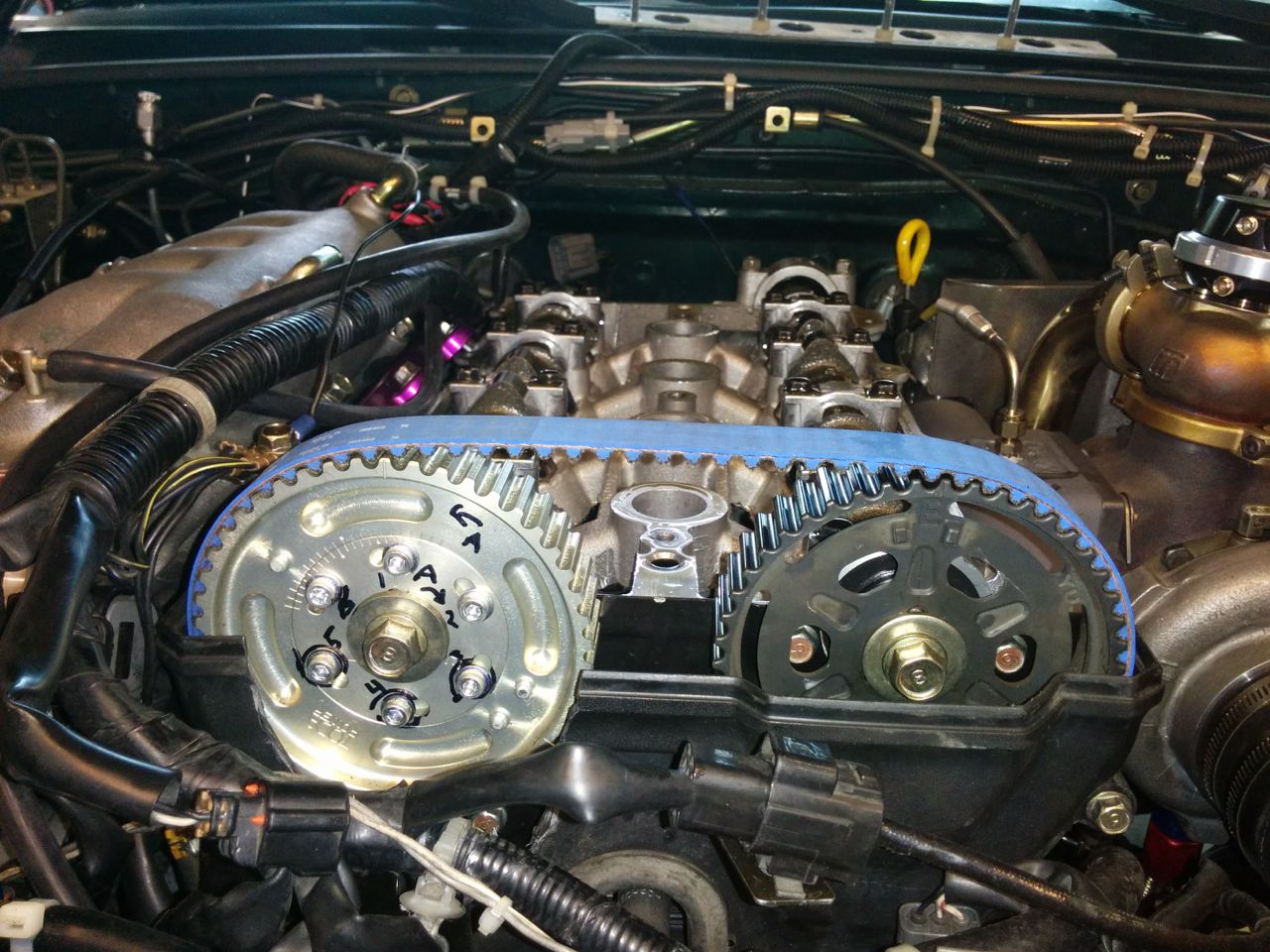
No problems with the wiring and this hole:
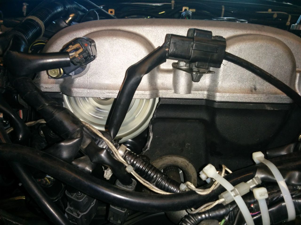
After a bit of practice, adjusting the gear like this is pretty quick. Loosen 3 bolts, turn the crank 360, loosen the other three, turn the crank to the right position (the Toda gear has an index scale on it), re-tighten the three, turn the crank again and do the last ones. Just don't burn your arm on the radiator while doing it.
So we ran it at -10, -5, 0, +5, and +10, reverting back to the base map each time. On each run we autotuned it at 150 kpa, then I extracted the data and graphed it:
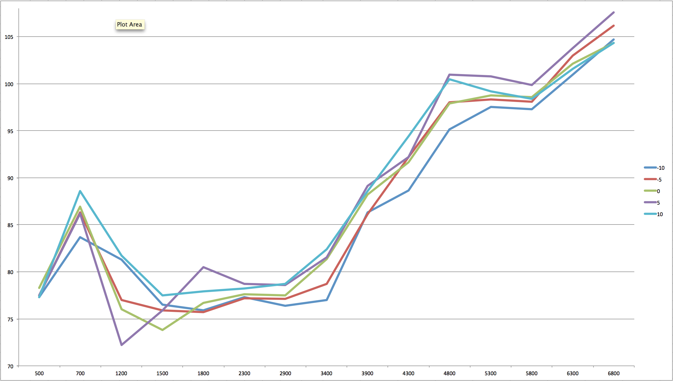
2900 and below are the 100 kpa row, 3400 and above are the 150 kpa row. I expected to see a low/high tradeoff in this, but nothing like that showed up. I dunno if this means it's too subtle to show up with just a quickie autotune and is buried in other factors, or if there's something else going on. The dyno will tell.
Does desirable cam advance change with the boost level?
--Ian
I have a spare valve cover, but I didn't really want to dremel it. The plastic timing belt cover is cheaper and I've also got a spare one of those, so that's easier.
No problems with the wiring and this hole:
After a bit of practice, adjusting the gear like this is pretty quick. Loosen 3 bolts, turn the crank 360, loosen the other three, turn the crank to the right position (the Toda gear has an index scale on it), re-tighten the three, turn the crank again and do the last ones. Just don't burn your arm on the radiator while doing it.
So we ran it at -10, -5, 0, +5, and +10, reverting back to the base map each time. On each run we autotuned it at 150 kpa, then I extracted the data and graphed it:
2900 and below are the 100 kpa row, 3400 and above are the 150 kpa row. I expected to see a low/high tradeoff in this, but nothing like that showed up. I dunno if this means it's too subtle to show up with just a quickie autotune and is buried in other factors, or if there's something else going on. The dyno will tell.
Does desirable cam advance change with the boost level?
--Ian
Reply
0
0