
Ian's 99 build thread


Looking good Ian.
I've got my Miata all packed as well. Rolling out of here at 6:30am to take the back roads up to Thunderhill.
(Santa Rosa to Middletown to Clear Lake to Williams and then up to the track.)
Distance is shorter for me and if I'm lucky I'll be able to avoid the morning commute.
I've got my Miata all packed as well. Rolling out of here at 6:30am to take the back roads up to Thunderhill.
(Santa Rosa to Middletown to Clear Lake to Williams and then up to the track.)
Distance is shorter for me and if I'm lucky I'll be able to avoid the morning commute.
Reply
 0
0

0
Thread Starter
Elite Member

Joined: Mar 2007
Posts: 5,306
Total Cats: 888
From: Santa Clara, CA
Back from Thunderhill. The car ran well -- the TSE radiator with the ducting was flawless, coolant temps were not an issue at all, which is the first time I've been able to say that on a 90F track day since before I first put a turbo on in 2002. Very, very pleased with that.
The EGTs, OTOH, were higher than I wanted. I'd turned it down to 180 kpa, but even so it would heat soak and by 3 or 4 laps in I was seeing 1500F+ EGTs for half the lap. I'm not sure if this is actually different than my previous setup or not -- the EGT sender is now mounted at the turbine inlet, rather than in the runners, so it's somewhat expected to see higher temps there. Also, the old westach EGT gauge didn't have any kind of warning light like the autometer one does, so I don't actually know how high they were going. Still, it does seem to be remaining higher than before.
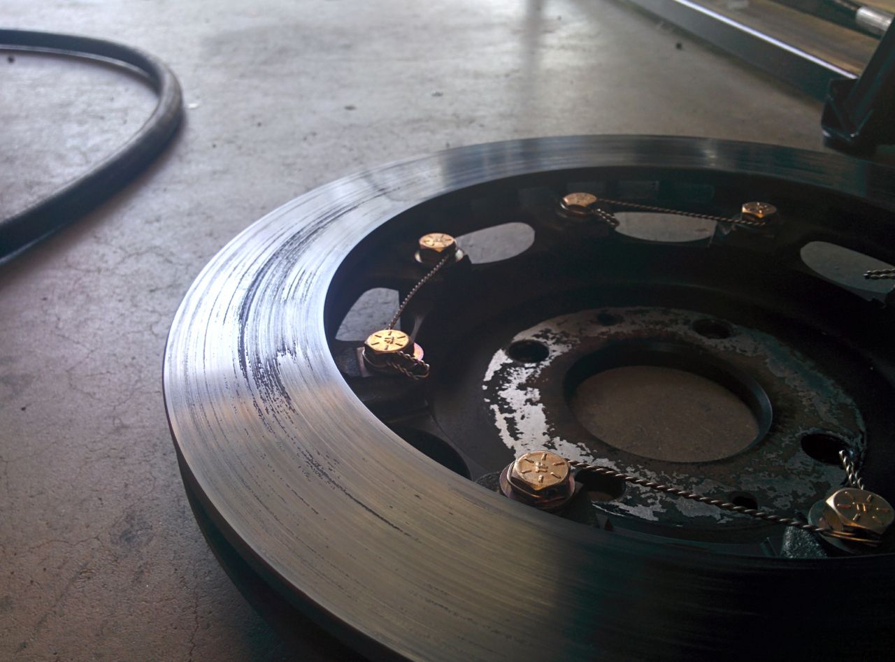
The 11.75s held up OK. Some deposits on the rotors, maybe I didn't bed them well enough? I dunno:
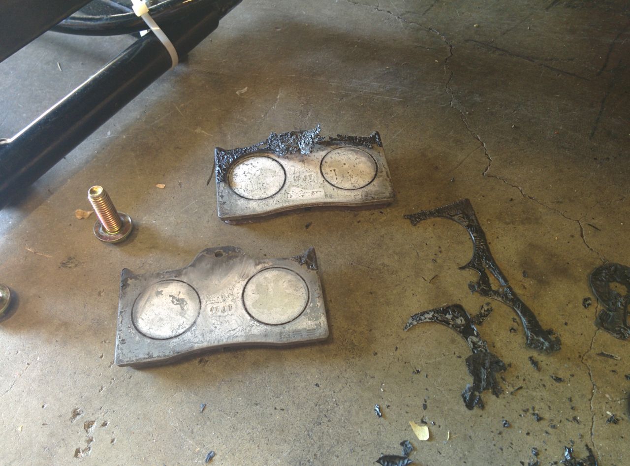
But the pads themselves held together fine, no tapering, no chunking like I was seeing before. OTOH, Thunderhill West isn't as bad of a braking track as Laguna.
I have no idea why someone thought it was a good idea to paint the backing plates on a set of DTC-60s, but...
I love the new track, it's a ton of fun in a Miata. I'd only driven it before as a part of the 5 mile circuit and that was in the Spec Racer Ford. IMHO it works and flows much better as a standalone track.
--Ian
The EGTs, OTOH, were higher than I wanted. I'd turned it down to 180 kpa, but even so it would heat soak and by 3 or 4 laps in I was seeing 1500F+ EGTs for half the lap. I'm not sure if this is actually different than my previous setup or not -- the EGT sender is now mounted at the turbine inlet, rather than in the runners, so it's somewhat expected to see higher temps there. Also, the old westach EGT gauge didn't have any kind of warning light like the autometer one does, so I don't actually know how high they were going. Still, it does seem to be remaining higher than before.
The 11.75s held up OK. Some deposits on the rotors, maybe I didn't bed them well enough? I dunno:
But the pads themselves held together fine, no tapering, no chunking like I was seeing before. OTOH, Thunderhill West isn't as bad of a braking track as Laguna.
I have no idea why someone thought it was a good idea to paint the backing plates on a set of DTC-60s, but...
I love the new track, it's a ton of fun in a Miata. I'd only driven it before as a part of the 5 mile circuit and that was in the Spec Racer Ford. IMHO it works and flows much better as a standalone track.
--Ian
Reply
0
0

Ian, glad to hear that the track day was a success .
Regarding your EGT coment i installed a CAN EGT from DYI AUTOTUNE and with it you have 8 TC imputs that will log, I used 4 for tuning but will use one on the collector and plan on using the remaining to log other important temps like engine and trans oil ambit etc. the only draw back is that i do not have an egt gauge i can look at only logs and by then it may be to late.
Regarding your EGT coment i installed a CAN EGT from DYI AUTOTUNE and with it you have 8 TC imputs that will log, I used 4 for tuning but will use one on the collector and plan on using the remaining to log other important temps like engine and trans oil ambit etc. the only draw back is that i do not have an egt gauge i can look at only logs and by then it may be to late.
Reply
0
0

Joined: Apr 2014
Posts: 18,643
Total Cats: 1,870
From: Beaverton, USA
I'm glad to hear thunderhill west is fun on its own. When I ran the 5 mile track it was too much change, going from fast sweepers to auto-x like turns.
Reply
0
0
Thread Starter
Elite Member
Joined: Mar 2007
Posts: 5,306
Total Cats: 888
From: Santa Clara, CA
Poked at the car a bit today. First I noticed the coolant overflow tank was empty, and the rad was low on coolant. I think this is because one time when I came off the track I didn't leave it idling for 5 minutes and it puked coolant out the overflow tank. Oops. 2 cups of distilled water filled it back up.
While taking it apart, I noticed that the anode on the radiator cap is noticeably smaller than it used to be. Do these dissolve at a constant rate based on hours of run, or is it something where once they've coated the metal parts in the cooling system it slows down?
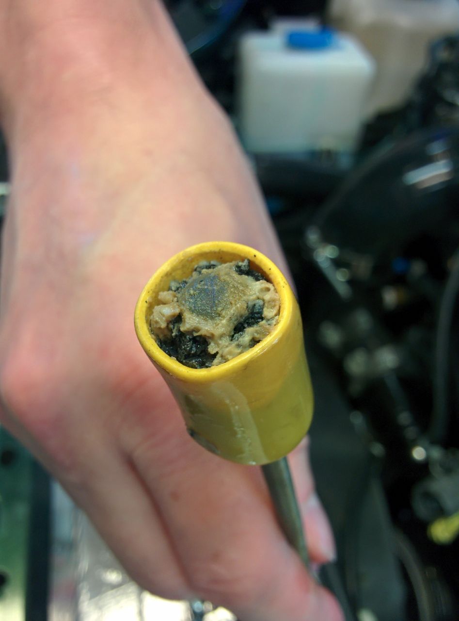
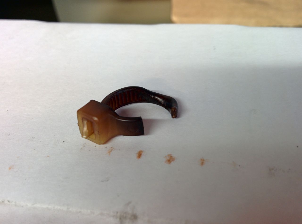
I also noticed that I had melted/burned the zip ties holding the lines onto the EWG. Oops. I guess I should replace these with metal hose clamps or something.
Then it was time to measure some pressures and see why the turbo isn't making the power I expected it to. I decided to start with turbine inlet pressure. First, we pop the EGT sender out and put in a compression fitting with some copper tubing:
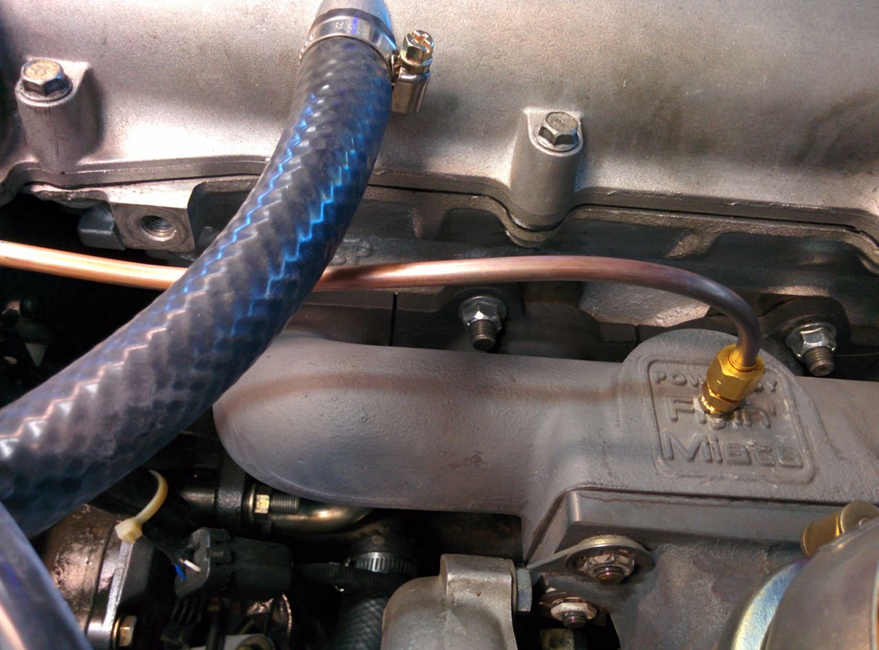
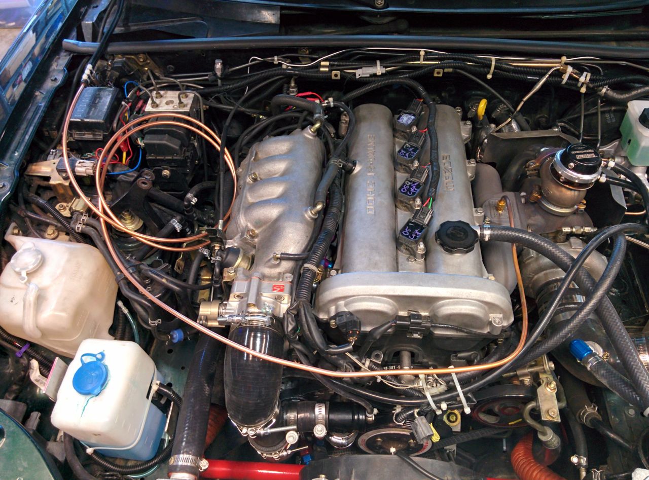
Route that to the other side of the engine bay:
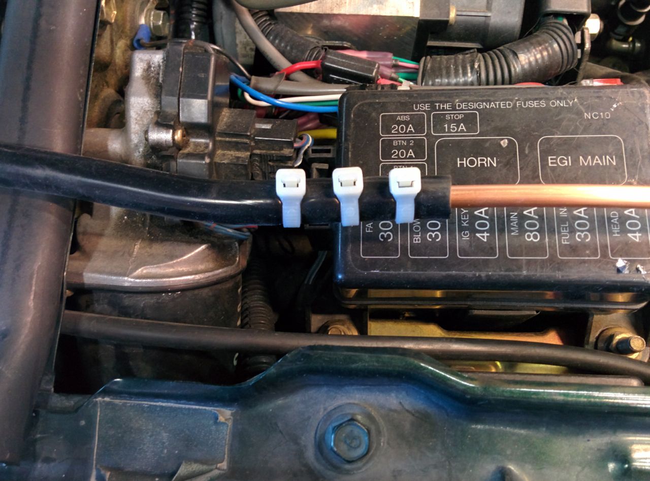
Secure it to a silicone hose. It sucks if this pops off while driving so extra zip ties:
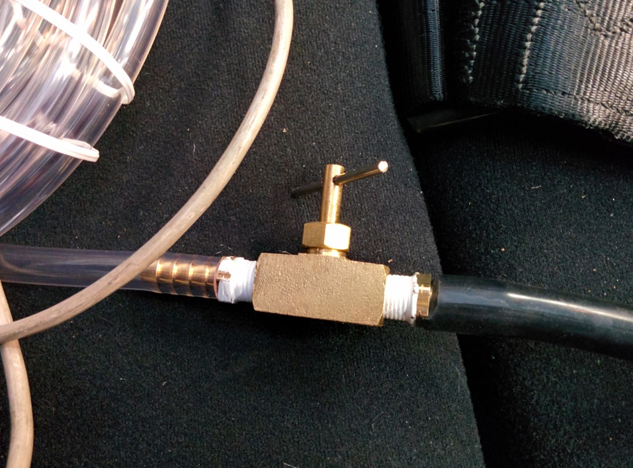
Then a needle valve so as to make a pneumatic low-pass filter to cut down on the amplitude of the pressure pulses:
And a pressure gauge on the other end:
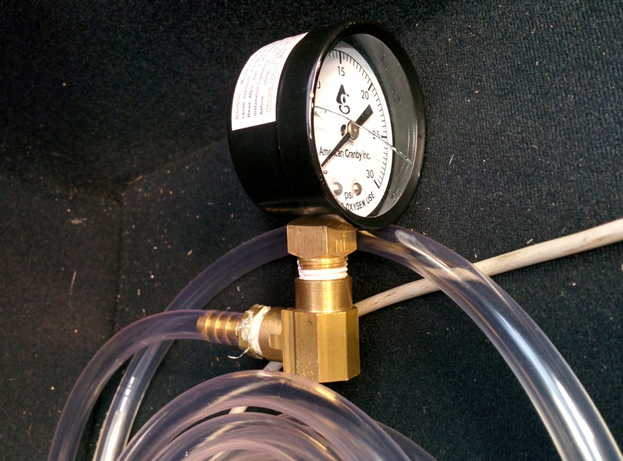
Then go out and run it at 18 psi and see what it says:
So it hits a peak of around 35 psi for 18 psi of boost. By itself, that value isn't actually all that useful, I really need to measure the pressure drop across the turbine, and compare it with the pressure rise across the compressor. I didn't really want to go back and buy more copper tubing and another gauge, so it seemed better to try to log this against RPM so that I could move the gauge from place to place and then put all the log data together.
I also have a 3 bar MAP sensor to install, so I decided to put that in, hook it to the turbine inlet pressure, and see if I could get the MS3 to log it along with MAP. "General settings" in TS has a "2nd map port" which I can configure as EXT_MAP and calibrate as a GM 3 bar MAP sensor. Unfortunately, while I can do that, I can't actually get it to do anything *else* with it. It does work (I can flip the main MAP input to using the 3 bar sensor and it responds to throttle blips and the like), but I can't figure out how to see both values at once.
Looking at the source, I can see that isr_rtc.s and ms3_asm.s have code to log both the primary and secondary map sensors, but when I turn on logging and look at the results in MegaLogViewer I don't see the second map sensor data. Does anyone know how to do this?
--Ian
While taking it apart, I noticed that the anode on the radiator cap is noticeably smaller than it used to be. Do these dissolve at a constant rate based on hours of run, or is it something where once they've coated the metal parts in the cooling system it slows down?
I also noticed that I had melted/burned the zip ties holding the lines onto the EWG. Oops. I guess I should replace these with metal hose clamps or something.
Then it was time to measure some pressures and see why the turbo isn't making the power I expected it to. I decided to start with turbine inlet pressure. First, we pop the EGT sender out and put in a compression fitting with some copper tubing:
Route that to the other side of the engine bay:
Secure it to a silicone hose. It sucks if this pops off while driving so extra zip ties:
Then a needle valve so as to make a pneumatic low-pass filter to cut down on the amplitude of the pressure pulses:
And a pressure gauge on the other end:
Then go out and run it at 18 psi and see what it says:
So it hits a peak of around 35 psi for 18 psi of boost. By itself, that value isn't actually all that useful, I really need to measure the pressure drop across the turbine, and compare it with the pressure rise across the compressor. I didn't really want to go back and buy more copper tubing and another gauge, so it seemed better to try to log this against RPM so that I could move the gauge from place to place and then put all the log data together.
I also have a 3 bar MAP sensor to install, so I decided to put that in, hook it to the turbine inlet pressure, and see if I could get the MS3 to log it along with MAP. "General settings" in TS has a "2nd map port" which I can configure as EXT_MAP and calibrate as a GM 3 bar MAP sensor. Unfortunately, while I can do that, I can't actually get it to do anything *else* with it. It does work (I can flip the main MAP input to using the 3 bar sensor and it responds to throttle blips and the like), but I can't figure out how to see both values at once.
Looking at the source, I can see that isr_rtc.s and ms3_asm.s have code to log both the primary and secondary map sensors, but when I turn on logging and look at the results in MegaLogViewer I don't see the second map sensor data. Does anyone know how to do this?
--Ian
Reply
0
0

Elite Member
Joined: Jul 2005
Posts: 6,420
Total Cats: 84
Reply
0
0
Thread Starter
Elite Member
Joined: Mar 2007
Posts: 5,306
Total Cats: 888
From: Santa Clara, CA
--Ian
Reply
0
0
Thread Starter
Elite Member
Joined: Mar 2007
Posts: 5,306
Total Cats: 888
From: Santa Clara, CA
Reply
0
0
Thread Starter
Elite Member
Joined: Mar 2007
Posts: 5,306
Total Cats: 888
From: Santa Clara, CA
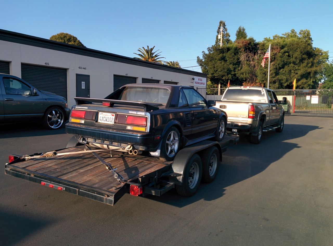
No Miata update from last weekend because I spent it doing other things, like retrieving TK's AW11:
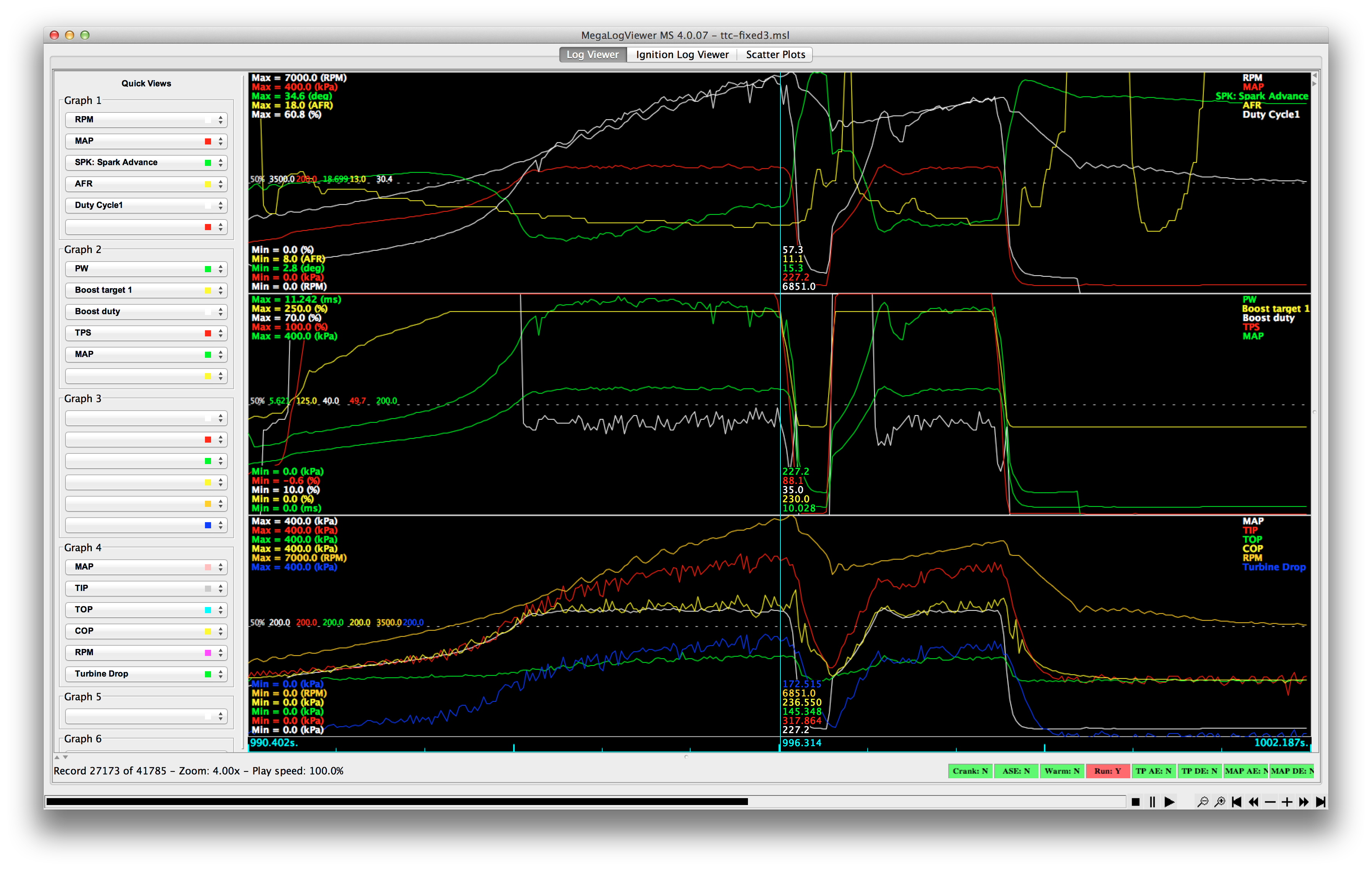
However, I did order some pressure sensors from Mouser/etc. Yesterday I hooked up the GM 3 bar MAP sensor to the boost signal (between intercooler and throttle body), a 4 bar MAP sensor to the compressor outlet, and a 7 bar MAP sensor to the turbine inlet. Wired them up to a couple of spare inputs on the MS3, did a little surgery on the log file to convert the raw voltage output to kpa, and got this (look at graph 4):
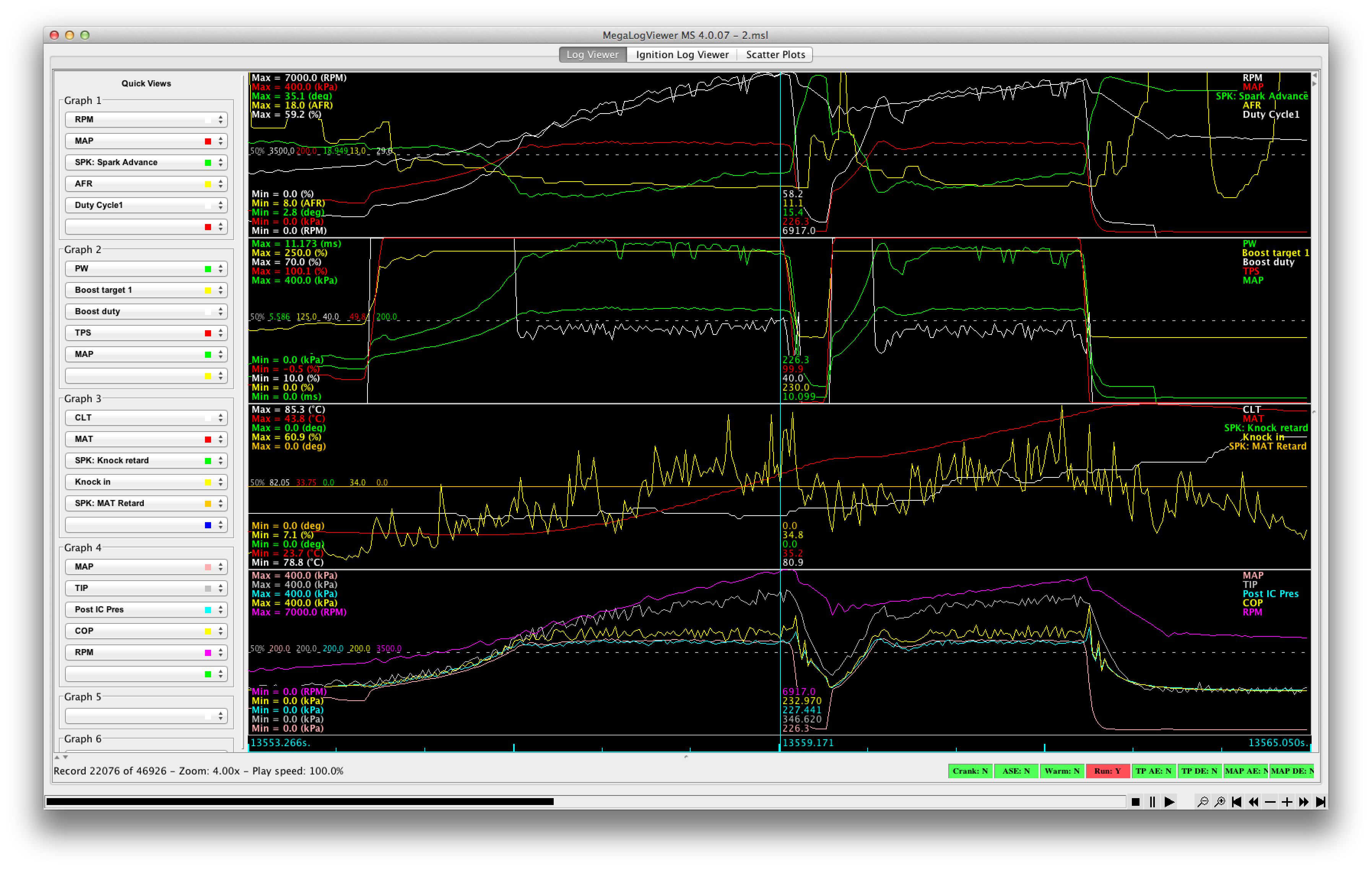
So, what does this tell me:
- Post-IC pressure and manifold pressure are pretty much the same, so the throttle body isn't a major restriction. I didn't think it would be, this was really just a sanity check.
- The compressor outlet pressure signal is noisy, but seems to be about 30 kpa higher than the manifold pressure at redline. That seems a bit high.
- Turbine inlet pressure is about 350 kpa at redline. I haven't measured turbine outlet pressure, but assuming there's ~ 5 psi of back pressure in the FM 3" cat & muffler, that's about a 200 kpa drop across the turbine for a 160 kpa rise across the compressor. That doesn't seem terrible.
- In a 800ms shift, the compressor outlet pressure drops to a minimum of 117 kpa and has recovered to full pressure about 500 ms later.
--Ian
However, I did order some pressure sensors from Mouser/etc. Yesterday I hooked up the GM 3 bar MAP sensor to the boost signal (between intercooler and throttle body), a 4 bar MAP sensor to the compressor outlet, and a 7 bar MAP sensor to the turbine inlet. Wired them up to a couple of spare inputs on the MS3, did a little surgery on the log file to convert the raw voltage output to kpa, and got this (look at graph 4):
So, what does this tell me:
- Post-IC pressure and manifold pressure are pretty much the same, so the throttle body isn't a major restriction. I didn't think it would be, this was really just a sanity check.
- The compressor outlet pressure signal is noisy, but seems to be about 30 kpa higher than the manifold pressure at redline. That seems a bit high.
- Turbine inlet pressure is about 350 kpa at redline. I haven't measured turbine outlet pressure, but assuming there's ~ 5 psi of back pressure in the FM 3" cat & muffler, that's about a 200 kpa drop across the turbine for a 160 kpa rise across the compressor. That doesn't seem terrible.
- In a 800ms shift, the compressor outlet pressure drops to a minimum of 117 kpa and has recovered to full pressure about 500 ms later.
--Ian
Last edited by codrus; May 10, 2015 at 12:28 PM.
Reply
0
0
Thread Starter
Elite Member
Joined: Mar 2007
Posts: 5,306
Total Cats: 888
From: Santa Clara, CA
I looked at the data some more. TK found some errors in my conversion, so I fixed those. I also noticed something interesting: Below ~ 4300 RPM (this is a 3rd gear run) the boost duty is 100%, meaning the BCS is closed. In that region, the post-intercooler pressure (PIP) is pretty solidly 2 kpa higher than the MAP value. Above 4300 RPM it's gotten close enough to the target boost of 230 kpa, and the boost control algorithm starts PWMing the solenoid. All of a sudden, PIP is now averaging something like 15 kpa BELOW the measured MAP. Initially I thought it was measurement error, so I went out and tee'd all four sensors together and ran the pressure in them up to 250 kpa and down to 20 using my compressor regulator and mityvac. I logged that, processed it, and all the sensors came to within 2-3 kpa of each other, so it's not a calibration error.
So I think what's going on is that when the BCS kicks in it's bleeding pressure off (cycling it into the WG can, then dumping it to atmosphere) and actually lowering the measured PIP value. So that value isn't useful.
So I recalculated the IC drop using COP and MAP, and added it to the graph:
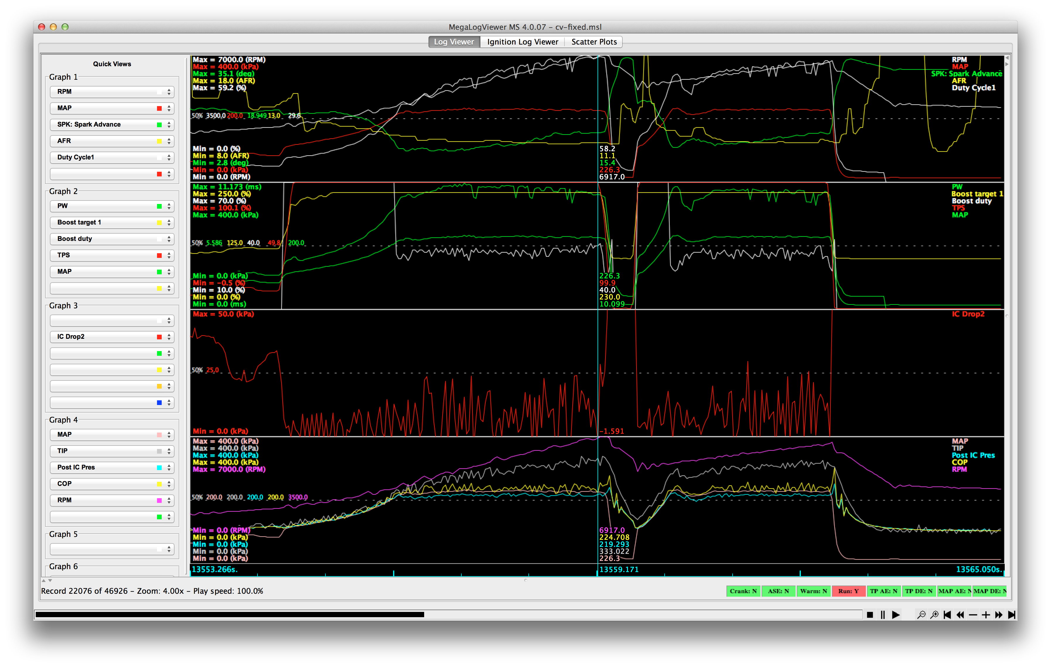
I need add some smoothing on the signal, either in software, with an RC filter, or something pneumatic, but using "visual smoothing" it shows an intercooler drop peaking at 25 kpa and averaging around 15 or so. That's much more reasonable.
--Ian
So I think what's going on is that when the BCS kicks in it's bleeding pressure off (cycling it into the WG can, then dumping it to atmosphere) and actually lowering the measured PIP value. So that value isn't useful.
So I recalculated the IC drop using COP and MAP, and added it to the graph:
I need add some smoothing on the signal, either in software, with an RC filter, or something pneumatic, but using "visual smoothing" it shows an intercooler drop peaking at 25 kpa and averaging around 15 or so. That's much more reasonable.
--Ian
Reply
0
0
Thread Starter
Elite Member
Joined: Mar 2007
Posts: 5,306
Total Cats: 888
From: Santa Clara, CA
OK, so I picked up another coil of copper tubing and compression fitting along with a spare O2 sensor bung, drilled & tapped the bung, installed it in the downpipe, and swapped the 3 bar MAP sensor from the (useless) post-IC pressure location to it. Now I'm measuring TIP, TOP, and COP.
So I'm seeing 6.5 psi of back pressure in the downpipe. Hm, that's not terrible, but it's not as good as I'd like to see it, either. I'm pretty sure it did better than that before, although I still can't find the data from when I measured it with the 2560.
Pressure drop across the turbine is 180 kpa, as compared to a 150 kpa rise across the compressor.
--Ian
Reply
0
0

Newb
Joined: Sep 2014
Posts: 21
Total Cats: 5
I'm using these calibration values:
That results in < 1kPa of error, excluding noise:
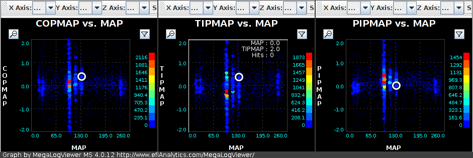
Here's the same data as from post #213. I've included MLV's smoothbasic(y, 5) for each of the 4 sensors (third chart), "[TIP] - [TOP]" (white on the bottom one), and "smoothbasic([COP] - [MAP], 5)" (red on the bottom chart).
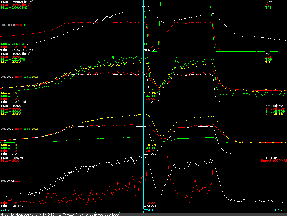
It looks like the intercooler pressure loss (SmoothCOPMAP) is mostly below 10kPa / 1.5psi, which ain't bad.
Code:
TIP     = 154.90 kPa/V - 31.9 kPa (MPX5700AP)
PIP/TOP =  62.78 kPa/V -  0.5 kPa (GM 3-Bar / MPXH6300A)
COP     =  82.05 kPa/V +  3.2 kPa (MPXH6400A)
That results in < 1kPa of error, excluding noise:
Here's the same data as from post #213. I've included MLV's smoothbasic(y, 5) for each of the 4 sensors (third chart), "[TIP] - [TOP]" (white on the bottom one), and "smoothbasic([COP] - [MAP], 5)" (red on the bottom chart).
It looks like the intercooler pressure loss (SmoothCOPMAP) is mostly below 10kPa / 1.5psi, which ain't bad.
Last edited by turbokitten; May 16, 2015 at 12:27 AM. Reason: improved image
Reply
0
0
Thread Starter
Elite Member
Joined: Mar 2007
Posts: 5,306
Total Cats: 888
From: Santa Clara, CA
So after satisfying myself that the turbo system didn't have any enormous restrictions in it, we decided to try more boost tonight. Filled it up with 100 octane, hooked up the GM 3 bar sensor as the primary MAP, and cranked the boost target to 240, then 250, then 260, then 280 kpa. A few thoughts:
- The 6 psi (nominally 7, but it delivers 6) on the TurboSmart EWG does an admirable job up to about 250 kpa. That's about a 3.5:1 ratio on the controllability, which is pretty good. TK got it to work above that by softening up the PID coefficients, but it's going to make for poorer response at lower boost targets. I think it's time to invest in some new springs, aiming for around 8 psi of mechanical boost.
- At 230 kpa, the back pressure through the cat & muffler is 140. At 260 it's 150, and at 280 it jumps to 180. The exhaust appears to be flow limiting around 260 kpa. It's the FM 3" downpipe, cat, midpipe & muffler. Since 3" exhausts are supposed to be good for 500+ hp, I suspect it's either the cat or the muffler design.
The midpipe connects to the muffler with a flange on the side which opens into a cavity, then the actual muffler section is a 90 degree turn from that. This seems like it would be suboptimal, but I haven't done any pressure testing to actually quantify the contributions of the two components yet.
- The car is pretty fast at 280 kpa. That might almost be enough, at least for a while. We'll have to see how it does at the dyno when I can tune the timing properly.
--Ian
Reply
0
0


Thread Starter
Elite Member
Joined: Mar 2007
Posts: 5,306
Total Cats: 888
From: Santa Clara, CA
Yeah, this is my FM 3" exhaust when I took it out of the box:
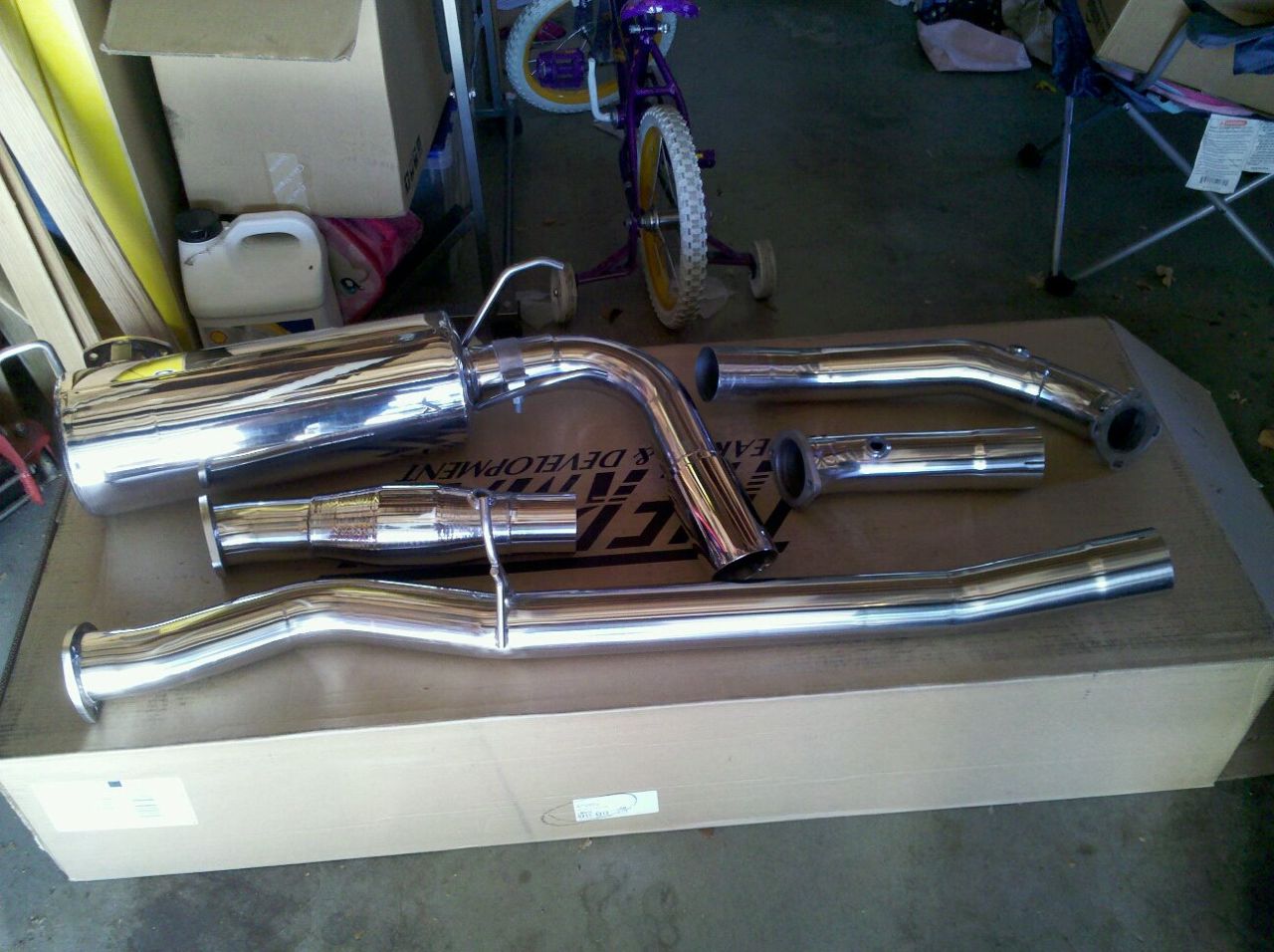
The old 2.5" exhaust (also FM) had a mandrel bent entry into the muffler:
<a href="http://photos.codrus.com/Miata/Turbo-Parts/9468809_CLKDb4#!i=1653873857&k=crW9htz&lb=1&s=A" title="Photo & Video Sharing by SmugMug"><img src="http://photos.codrus.com/photos/i-crW9htz/0/L/i-crW9htz-L.jpg" title="Photo & Video Sharing by SmugMug" alt="Photo & Video Sharing by SmugMug"></a>
I don't know why they didn't do that with the current one. I can see that there's limited space, so perhaps that's why? Looking under the car though, there seems to be room for the bend if the muffler were moved towards the rear of the car by six inches or so
That said, it's not a significant restriction at 15 psi and ~ 250 rwhp, so I guess one could argue it's the right solution for the majority of FM's customers. I may have to try a custom setup like yours, G.
--Ian
Reply
1
1
I recognize that 2.5" exhaust. So should Vlad 
Getting the bends smoothly around the suspension, subframe, braces, axles and diff was the hardest part. If you decide to try one of the great big 5x11x22 magnaflows, I'd recommend a center/offset or offset/offset muffler rather than a center/center. I chose to go with the "supposed to be quieter" Magnaflow 12579 center/center muffler and that made things more of a challenge than we were looking for on the 180� section.
I'll see if I can measure back-pressure for you once I get things together.
Reply
1
1
Thread Starter
Elite Member
Joined: Mar 2007
Posts: 5,306
Total Cats: 888
From: Santa Clara, CA
I recognize that 2.5" exhaust. So should Vlad
Getting the bends smoothly around the suspension, subframe, braces, axles and diff was the hardest part. If you decide to try one of the great big 5x11x22 magnaflows, I'd recommend a center/offset or offset/offset muffler rather than a center/center. I chose to go with the "supposed to be quieter" Magnaflow 12579 center/center muffler and that made things more of a challenge than we were looking for on the 180� section.
I'll see if I can measure back-pressure for you once I get things together.
How do the center/offset ones work? Is it still a straight through pipe just running at an angle, or is there a corner inside it?
I hear good things about Burns Stainless mufflers -- aside from being expensive, any thoughts on those?
--Ian
Reply
0
0


