When you click on links to various merchants on this site and make a purchase, this can result in this site earning a commission. Affiliate programs and affiliations include, but are not limited to, the eBay Partner Network.
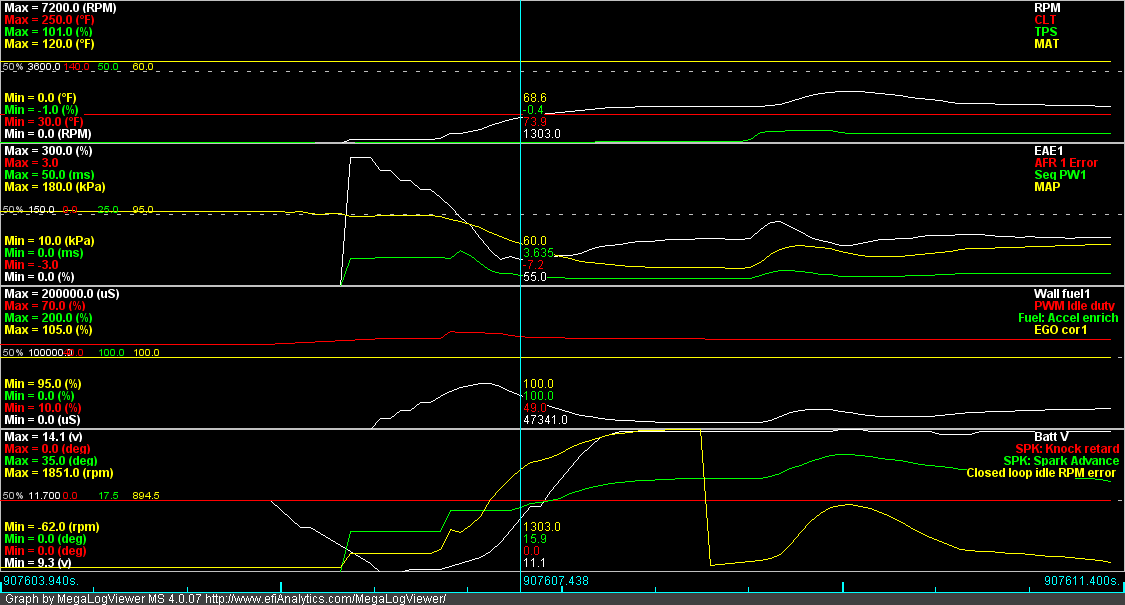
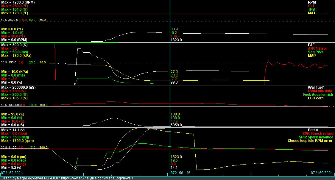
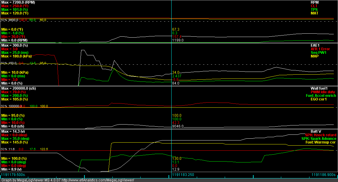
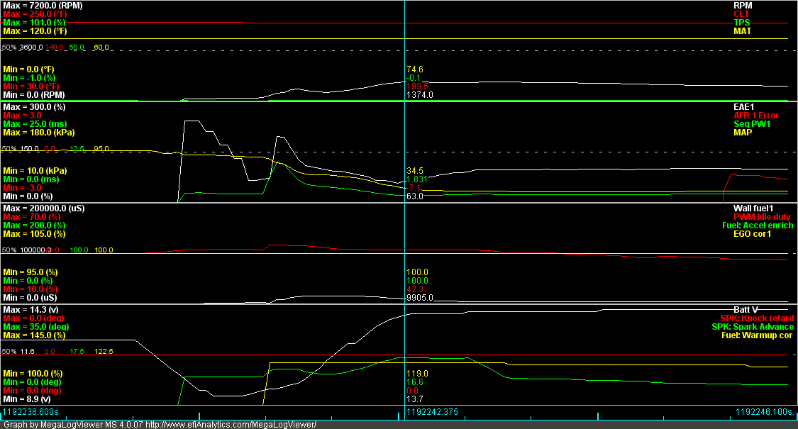
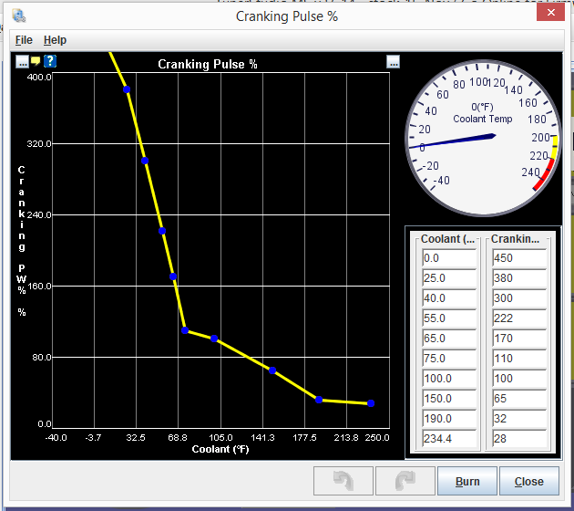
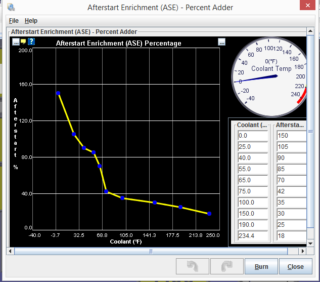
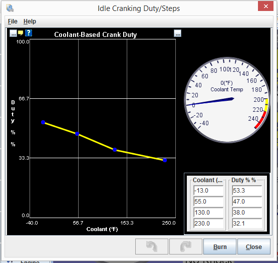
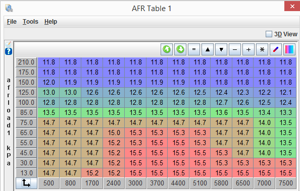
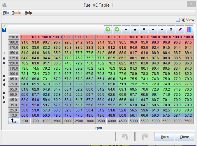
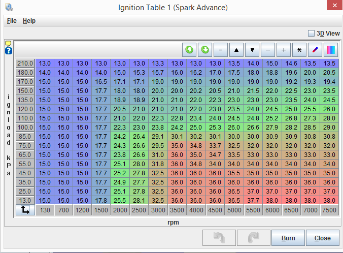
Here are my starting curves. Lots of them because, once MS moves from crank to run, lots of things affect the fueling: AFR Table (if in the fuel calculation)l; VE in the areas of 90 kPa and 500 RPM; Cranking Pulse; ASE; Ign Adv (Note, I'm using 10 BTDC during Cranking). Also, I'm transitioning from Crank at 375 RPM. I don't think this is particularly critical.
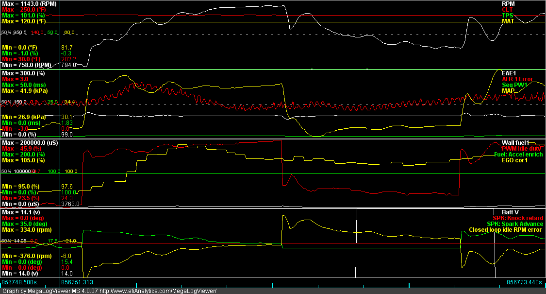
Basic results is that I starting with CLT between 70 and 205*F in less than 2 seconds from key turn.
<p>My temporary coolant fix was more temporary than anticipated. Started leaking again... twice. So I don't have the bungs on for full hard lines, but I added one mostly hard line. I'm no Hornetball, but I think this should work.</p><p>Leaky connection (hose to line):</p><p><img src="http://cimg1.ibsrv.net/gimg/www.miataturbo.net-vbulletin/480x640/80-16_8ac1305c66a03289e66ca34ae889c29b59f69158.jpg" title="" /></p><p>Steel because I don't trust Al at the CHRA. Just a gut feel sort of thing.<br /><img src="http://cimg3.ibsrv.net/gimg/www.miataturbo.net-vbulletin/640x480/80-18_e42e1444f2cda033a30843f42763af01b7afe802.jpg" title="" /></p><p>Fitting Installed<br /><img src="https://cimg4.ibsrv.net/gimg/www.miataturbo.net-vbulletin/640x480/80-19_71ae0bea8735997313a6dcf322f1c60adbc47728.jpg" title="" /></p><p>Side View:<br /><img src="https://cimg5.ibsrv.net/gimg/www.miataturbo.net-vbulletin/640x480/80-20_b063c4b6f292d09518e48117918796670b859268.jpg" title="" /></p><p>Front View:<br /><img src="http://cimg6.ibsrv.net/gimg/www.miataturbo.net-vbulletin/640x480/80-21_b4716d42bdbefd799f08b7db478facca4544c6da.jpg" title="" /><br /><br />Used 3/8" brake line and -6AN fitting. Plan is to put weld -6AN bungs on the front and mixing manifold when I do coolant re-route, and then have full length hard lines for both in and out; and also the oil line.</p>
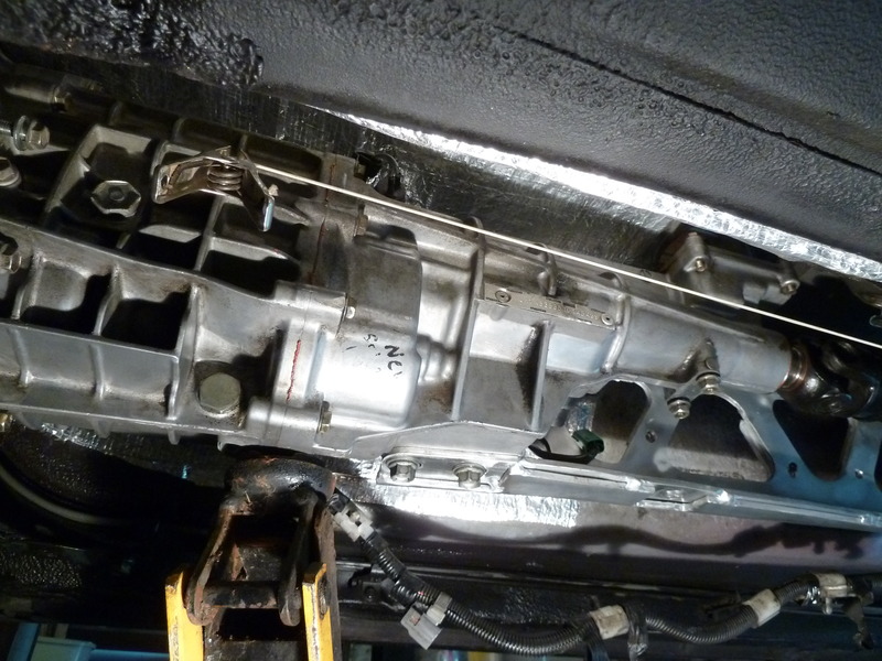
"I also adjusted the PPF to XMSN to get the height at nominal. Loosened the bolts, jacked to max height, tightened the bolts, removed jack. Ended up at 2.5" when service manual says 2.37 - 2.83."
I looked up ppf, but I coudn't find what xmsn means... I'm guessing this effects ground clearance?
Only update I have is more tuning, and a new radio. I will post the radio install when I get a couple more photos.
Purpose of the PPF-XMSN is to align the tail shaft properly with the drive shaft. Ideally, the hook joints (aka universal joints) should be at identical angles for smoothest rotational transfer. There is a spec on the height of the rear of the XMSN which I presume is to obtain that ideal relationship.
Here's what I did, maybe it works the same/better.
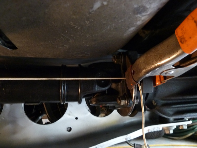
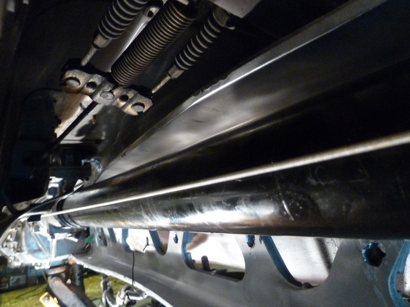
String line method. There is a casting line that runs down the exact center of the output shaft.
The other end of the string runs by the center of the u joint.
Then adjust the PPF and sight down the drive shaft until everything is straight and tighten the PPF bolts.
Ah, ok, that makes sense. Would this adjustment effect high rpm shifter noise? Past 6300rpm my shifter (miata roadster extended, with aluminum shift ****) vibrates a lot, and is quite noisy.
Driver's floorboard is soaked. Rain rail drains are open, but no water around the driver's side one, so maybe top is ripped or water is going between rail and body. Sounds like time to put it in the shop and finally start (last year's) winter projects. Roll bar, seat lowering, COP's, EBC, FINALLY replace the exhaust manifold, etc.
Step 1, pull out interior and find the leak. Gonna miss driving the car, but it will be better after this.
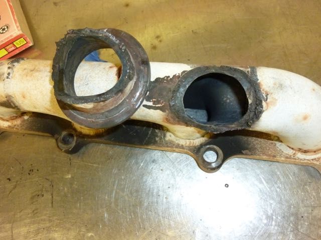
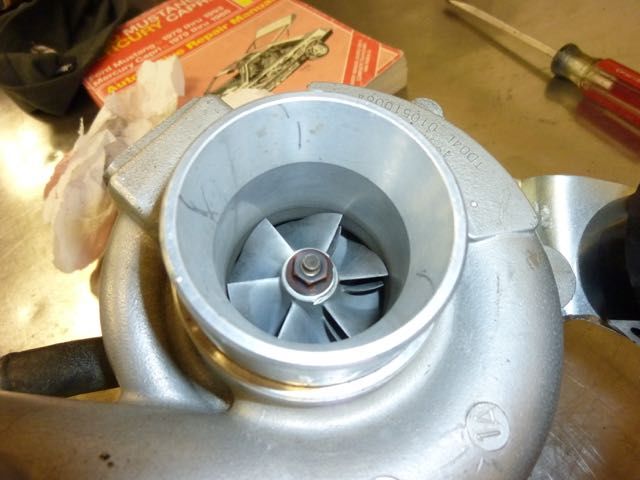
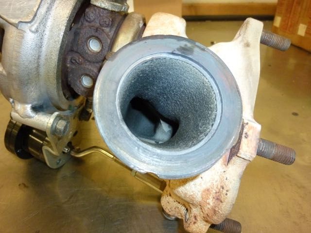
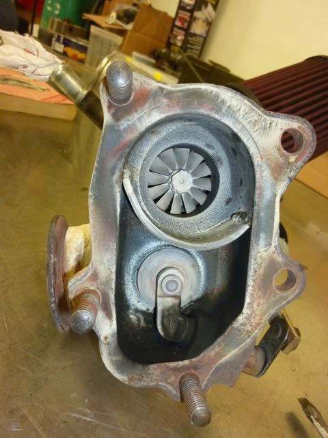
Right after the last post, another leak took the spotlight. I had been running the car with cracked Exhaust Manifold joints for a year now. They would seem to close up once warmed, and the replacement outlet flange has not been competed. Well, last week, the old Manifold fell apart. Turbo was supported (quite well) by the downpipe.
On that first night, I had also planned to pull the MS3 and get PCB pics for Reverant as he is going to guide me in adding some I/O's... but I forgot to do that.
After pulling Turbo and Manifold:
AFR went screwy, so I turned off EGO Correction and drove conservatively. Went well, and the car even idled fine (I have lots of correction running at idle due to hot restarts).
I still don't know all of the water ingress issue, but think that it was a clogged rear drain. I don't have a picture, but the carpet is now pulled up (not yet out) to let it dry. The paint under the carpet is all still intact. No rust on rear shelf either. (I don't have pics of that).
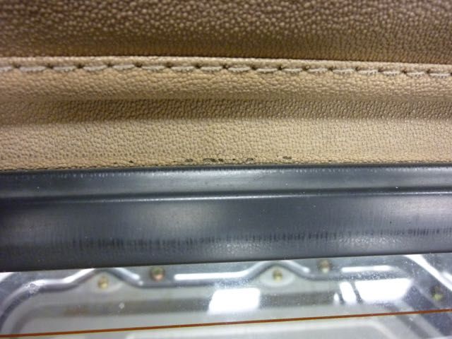
Here is a shot of the top at the glass, showing that, regardless of the primary leak, it is time to replace the top.
Some other general shots of the turbo. Looks solid after 10K miles.
Other bad news: The Spar Urethane is not holding up as well as hoped / expected. It is frosty along the top. I will re-apply, with less thinning, and more final thickness.
MY QUESTION:
I will be taking the carpet completely out. Roll bar and sound deadening is going in, along with possibly lowering the rear seat mounts. Should I cut the carpet into left and right pieces, or should I pull the radio / heater tower? If I pull the tower, can someone point me to a write-up or video how-to for an NB?
Second Question: Anyone using the memory card in MS3 for data-logging? Worth doing? Is data transfer into MS / MV working directly now?
Finally got SIL's mustang finished and running 1/4 miles. Thus am working on the Miata.
Got the Inj harness simplified, and the COP harness built.
This is how I made splice crimps from spare crimp pins by cutting off all but the crimp section:
Then crimped the splices in the COP harness and covered with glue-lined shrink tubing (bottom connections shows crimp, top shows finished with shrink:
Put in jumpers on MS motherboard in places where I wished to utilize OEM harness wires (EBC, Sequential COP, Baro Sensor), and installed the SD card. I have re-used the front OEM mounting bracket for the R2 of the MS3-Basic (the long version), but have not yet made a rear bracket.
Then loaded the pre-planned, modified VE table in anticipation of return fueling system, and updated to 1.4.1 F/W on MS3s. I used the new TunerStudio version that allows loading of FW from TS. It worked without issue. In fact, I accidentally pulled the USB cable out during the download, and was able to recover.
Made front neck block-off plate and started playing with re-route.
Pulled FPR from tank and mounted European rail mounted FPR onto rail. While in back of car, pulled the aluminum panel for roll bar mounting.
Lastly, SIL cut the hole in the new log, so I mounted turbine housing and log and we tacked the manifold outlet piece. Removed all so the outlet could be tigged to the log. Then I'll blend the inside.
More pictures when I go back over, as I have too many words without pictures.
Last edited by DNMakinson; Sep 10, 2016 at 07:34 PM.
Reason: Added better and more pictures
Some Progress:
First, Finished the mounting for the MS3 Basic (Rev 2, which is thinner than Rev 1, but longer than Rev 3). Works, but Main Harness connectors are quite tight plug in. The Serial box will mount to the brake side face via Velcro.
I used the old rear-most mount from stock, and just made an angle piece for the firewall bolt.
Fuel System now competed, along with new filter:
(Dang, I forgot the engine photo, showing the European FPR)
Anyway, I used an 8mm (5/16") supply line from another NB1 for the return. It fished in without having to bend it. I then made the short nylon line from filter outlet to supply, and remade the nylon return line. The lines from the top of the tank to the filter area were hard to fish due to a foam seal. I fished from above with a coat hanger.
I used the existing small line for the vent, removed all of the electrical sensors and valves so that things run: Anti-rollover, out to fill, from fill, down the small tube, to the filter and then to the original vent.
Shown below is a short connector joining the line from the fill tube, to the small nylon going down to the vent.
Here is a Schematic of what I did with the vent. Return just goes to return:
Then I added a little more bracing in the rear by replacing the standard NB1 with a Mazdaspeed version I had.
Last edited by DNMakinson; Oct 15, 2016 at 11:42 AM.


 0
0