When you click on links to various merchants on this site and make a purchase, this can result in this site earning a commission. Affiliate programs and affiliations include, but are not limited to, the eBay Partner Network.
Because of where I'm putting the intake I have to extend my MAF sensor wires about 6". I looked at the wires before cutting and they all seemed like standard different color wires. Fast forward 30 minutes later when I go to solder them all back together and there are two wires that are exactly the same damn color. Doh! Pin 1 and pin 8 wires on the MAF sensor are a solid light blue with no markings, and they are EXACTLY the same color. Which seems odd because they are two completely different functions. Pin 1 is the IAT sensor signal and pin 8 is the humidity sensor signal. I tried the multimeter on the two ends of the wires that go back into the harness looking for anything that would differentiate them, and nothing to note (harness doesn't have power yet).
Any ideas on how to figure out which wire goes where? I'm not at the point of starting the engine yet, so it may have to wait until then.
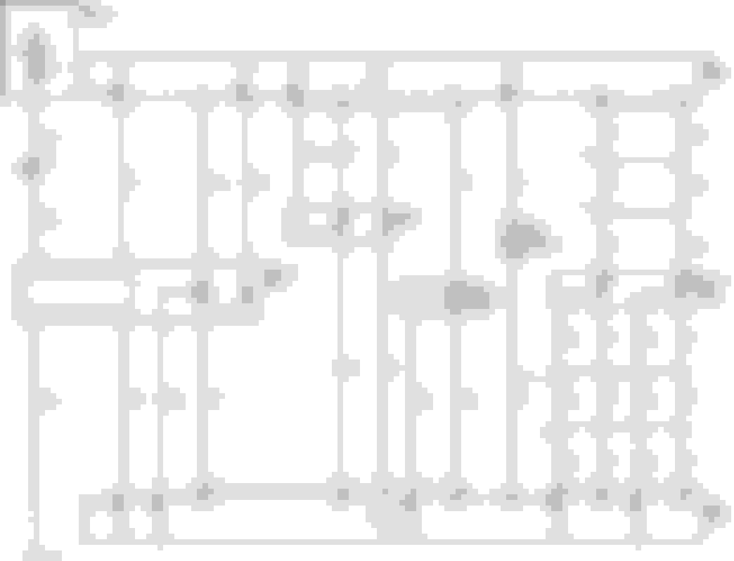
So.. it's pin 1 and 8 you'll need to tone out to the X2 (which iirc is the gray connector - I doublechecked it's the black) on the ECM to either pin 49 or 15.
So.. it's pin 1 and 8 you'll need to tone out to the X2 (which iirc is the gray connector - I doublechecked it's the black) on the ECM to either pin 49 or 15.
So.. it's pin 1 and 8 you'll need to tone out to the X2 (which iirc is the gray connector - I doublechecked it's the black) on the ECM to either pin 49 or 15.
Just to confirm, is this the same orientation for pin 1 and 8 you are seeing?
I pulled the info from this which doesn't have pin orientation - but you should be able to match the colors from the plug to figure the order (a lot of GM plugs have a orientation mark embedded in them). Black/White is 7, Gray/White is 2.
Tunnel removed and trans mount installed. Added rivet nuts for the tunnel bolts and got the new harnesses bolted into the car. Working on the coolant pipes now and almost done. The new shifter from V8R (redesigned) should be here soon.
All that is left:
Mount expansion tank/recovery tank and run coolant hoses
Install V8R shifter
Mount and weld back half of the exhaust
Chassis wiring (the big one)
Exhaust components laid out for mock-up and awaiting my latest order of pie cuts from stainless bros. Pro tip, get the 4.5 degree 1D 5-piece kits. I've found those are the easiest to work with out of the four different versions and give super clean bends. I have to give it to Spintech, the owner Ron outdid himself on making the custom flat ovals for me along with the transitions to 2.5" round tube. And the muffler is gorgeous! I had never heard of spintech (https://spintechmufflers.com) and found them after searching for a compact dual inlet/outlet 2.5" stainless muffler. For any exhaust I do in the future, I'm calling them.
Also got the Radium expansion tank and recovery tank mounted up. Need to get the coolant hard line bead rolled that goes to the back of the motor and then the coolant system is done.
Few questions for the guys that have been down this path before me.
I'm using a derale fan controller with a temp sensor tapped into the outlet on the front to tun on the fan. Can I piggyback off the sensor to get a coolant temp reading displayed elsewhere? (AIM Dash in my case)
Or can that be pulled from the LFX ECU?
What data other can be pulled from the LFX ecu to display?
For E85, can the % ethanol be pulled from the GM sensor to display that somewhere as well?
E39 has pretty substantial OBDII PID support. I don't know the AIM specifically, but I do recommend grabbing Torque app for android and a cheap ELM327 bluetooth OBDII adapter - it does look like there's a mode22 (extended diagnostics - OEM specific, not well documented) GM pid for ethanol content. I'd rather pull coolant info from the ECU.
A bunch of pics. Exhaust is almost done. Driver side finished and the passenger side is just missing the muffler to side pipe joiner which I'm going to make tonight. Also need to add an H-pipe before the muffler. Coolant system is done, you can see the routing in the pics. I welded on tube extensions for the upper and lower coolant pipes so I don't have to run long rubber hoses. I mounted the derale fan controller's temp sensor on the bottom of the coolant outlet at the top of the engine.
Please elaborate. Where should there be heat shielding specifically? There is heat shielding on the bottom of the tunnel that is removed in the pics, but not really anywhere else. There wasn't any on the previous setup with the miata turbo motor (except around the turbo) and I didn't have any issues from it. I could wrap the downpipes and exhaust pretty easily.
I'm looking specifically at the exhaust running within the tunnel cooking legs and other parts of both occupants. And the spot immediately under the seat might melt the jellybeans in your pocket.


 0
0