
Pat's Ebay Turbo Compound Boost Build


Joined: Apr 2014
Posts: 18,643
Total Cats: 1,870
From: Beaverton, USA

Reply
 0
0

0


Thread Starter
Elite Member
iTrader: (16)
Joined: Aug 2007
Posts: 9,406
Total Cats: 559
From: Houston, TX
Ended up making this bellhousing twice. First time I used the factory bore for the bellhousing, and made some curved shims the exact thickness to make up the distance. Plan was to tach weld the shims on to make them part of the assembly. But I had to weld up the housing to redrill the bolt holes. That warped the bore such that the shims no longer worked on a warped circle after the welding. So ended up rewelding the bolt holes and bore, and then remachining both. Good news is now the bore is the right size so no shims at all, and it's a slip-fit onto the trans just as the stock bellhousing fit on the C4.
Took many hours to get the exact location of the bore, and the bolt circle all exactly correct. I measured a block and two bell housings to confirm I had the measurments accurate within 1/2 a thousandth. Took about 3 hours to do the machine work once the dimensions needed were known and the part was centered and zero'd out on the machine.
Took many hours to get the exact location of the bore, and the bolt circle all exactly correct. I measured a block and two bell housings to confirm I had the measurments accurate within 1/2 a thousandth. Took about 3 hours to do the machine work once the dimensions needed were known and the part was centered and zero'd out on the machine.
Reply
0
0
Thread Starter
Elite Member
iTrader: (16)
Joined: Aug 2007
Posts: 9,406
Total Cats: 559
From: Houston, TX
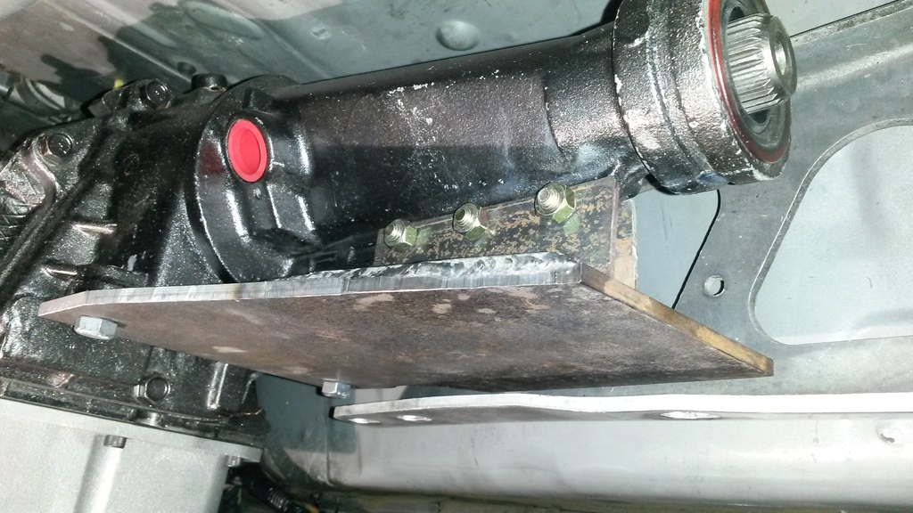
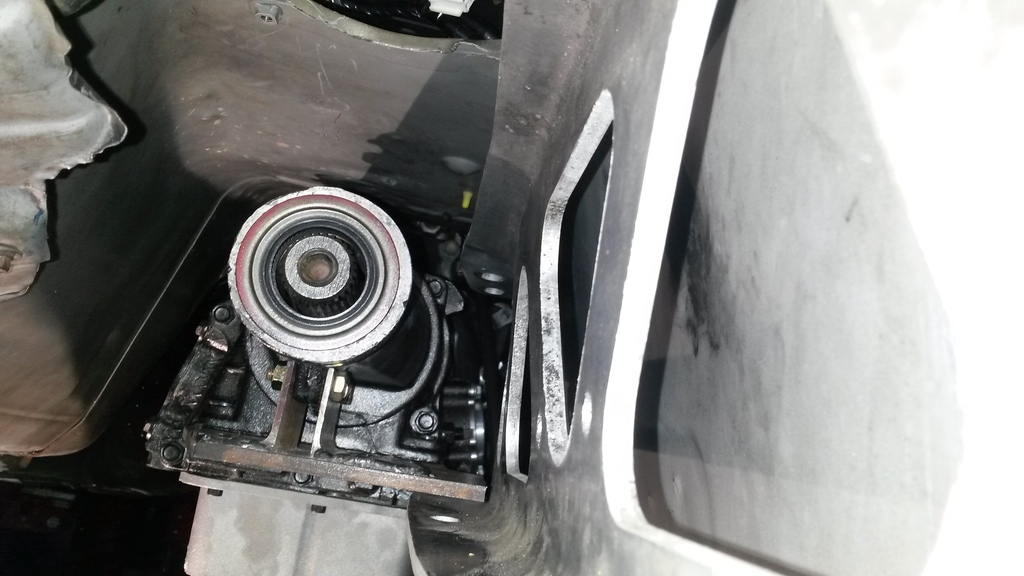
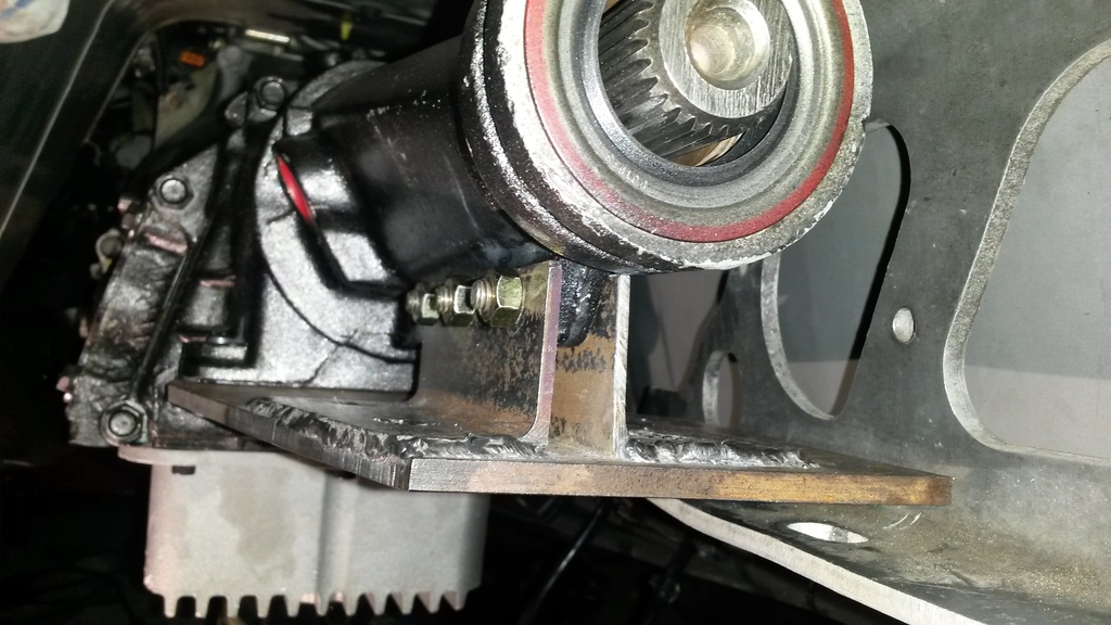
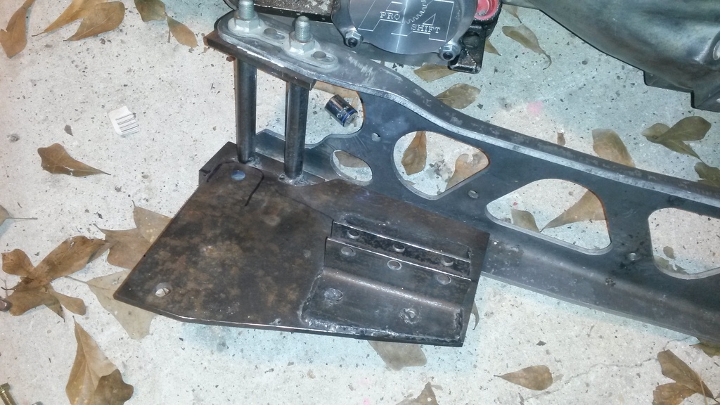
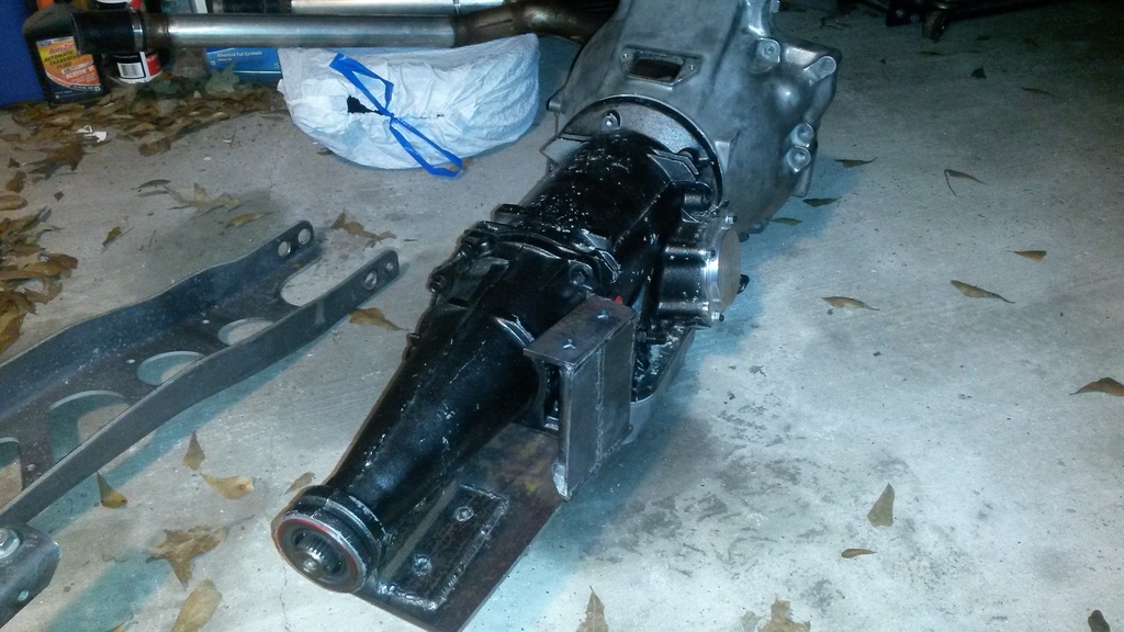
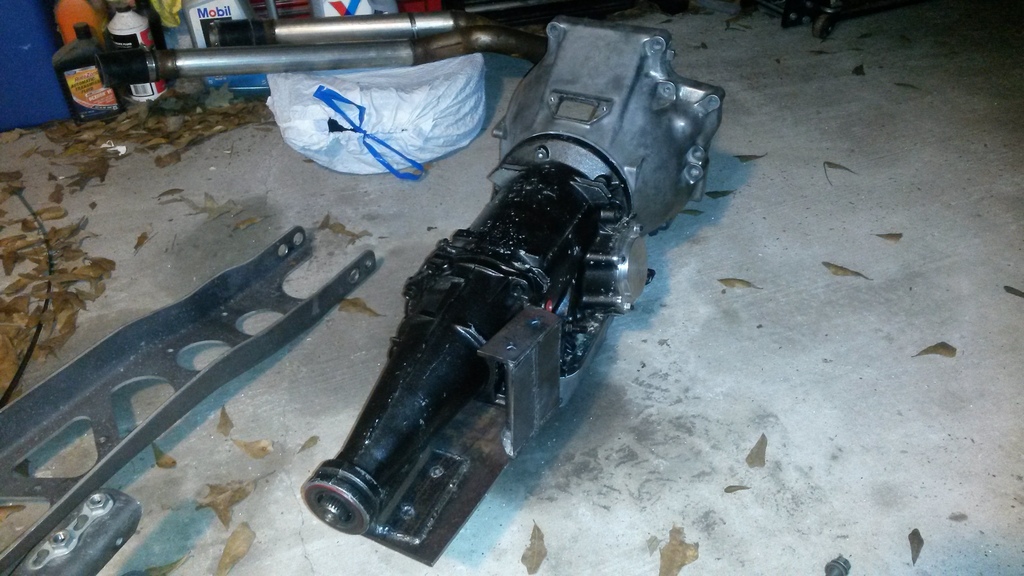
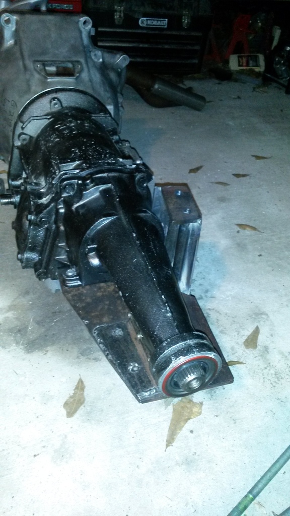
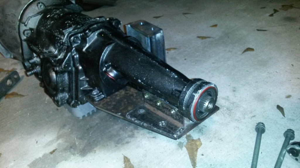
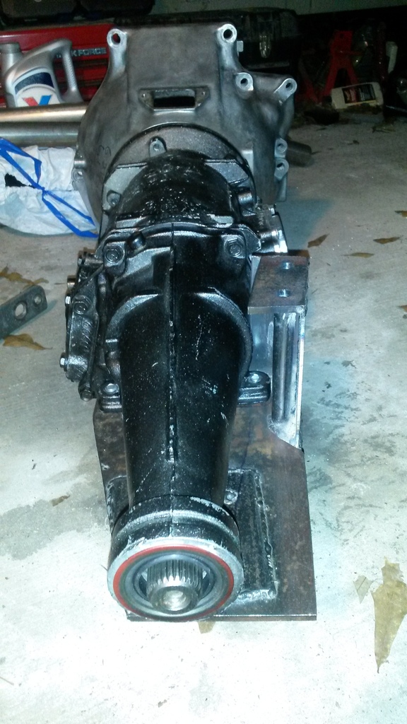
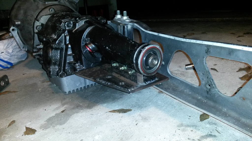
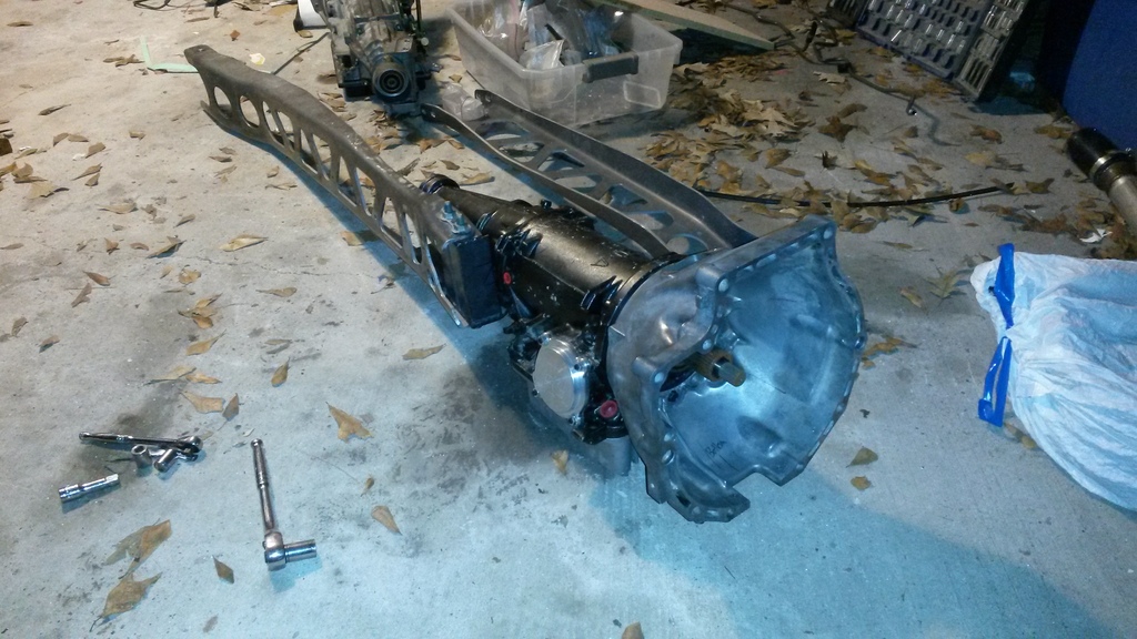
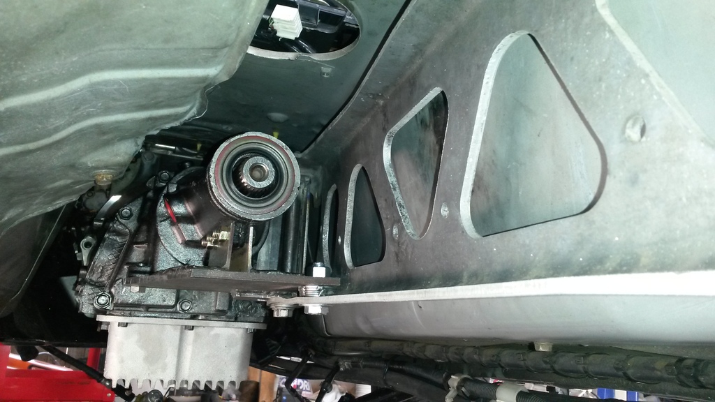
I started building a custom rear diff mount. Wasn't happy with it, and stopped working on it went back to looking at keeping the PPF as mazda did. I finally had an idea for how to build an adapter that would allow me to bolt the PPF to the trans. It was hard to design one that is strong enough, rigid enough, captures enough mounting points on the trans to not overstress the case, keep the simple instalation as mazda designed it, and probably some other things I'm not thinking of right now.
Anyways decided to try that route. It's not done yet, but it's almost done. Gotta clearance a spot, and add one more simple pinch-bolt and spacer to give it a bit more strength (bolt going same spot mazda put a 3rd bolt on the manual transmissions for the PPF, behind the big 2 bolts about 6 inches)
Pics of where it's at right now.


Reply
4
4
Thread Starter
Elite Member
iTrader: (16)
Joined: Aug 2007
Posts: 9,406
Total Cats: 559
From: Houston, TX
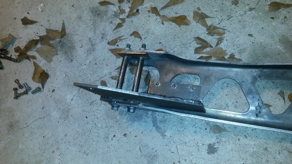
And for the curious, that bracket weighs 6 lbs. I'm sure it could be lighter, I had steel and made it with material I had on hand. Also my portable band saw broke, so about 1/2 the cuts were made by hand with a hack saw.
Reply
0
0

Reply
0
0
Thread Starter
Elite Member
iTrader: (16)
Joined: Aug 2007
Posts: 9,406
Total Cats: 559
From: Houston, TX
Ian,
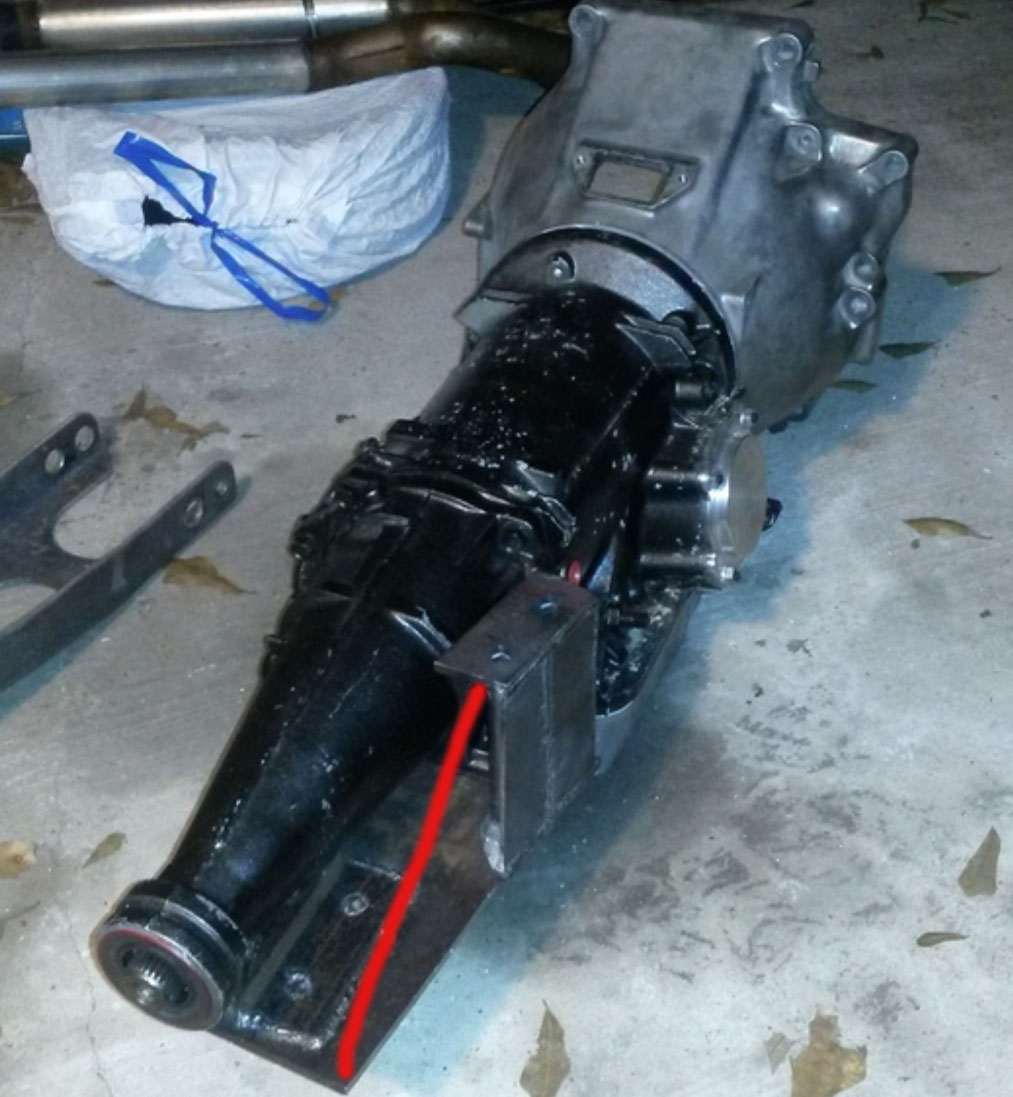
I was going to do that, but it's pretty rigid as is, so I stopped. Once I add the 3rd bolt (about where the bottom of your red line is) it will box everything in and at that point should be plenty rigid enough. Going to add the 3rd bolt now and test in car, see how it looks.
I was going to do that, but it's pretty rigid as is, so I stopped. Once I add the 3rd bolt (about where the bottom of your red line is) it will box everything in and at that point should be plenty rigid enough. Going to add the 3rd bolt now and test in car, see how it looks.
Reply
0
0


EDIT: NM, I see there is a panel on the forward end of the bracket providing shear on the perpendicular axis.
Reply
0
0

So the C4 has that same rib with the 3 weird holes in it that I cant figure out what they're for as the T5. It looked great to use on the T5 too, but I was afraid it would break off the aluminum housing since it looks so wimpy and nothing I could find bolted to it in the cars it came from.
Reply
0
0
Elite Member

Joined: Mar 2007
Posts: 5,306
Total Cats: 888
From: Santa Clara, CA
Thinking about it some more though, the engine is going to twist it, so yeah.
--Ian
Reply
0
0
Thread Starter
Elite Member
iTrader: (16)
Joined: Aug 2007
Posts: 9,406
Total Cats: 559
From: Houston, TX
So the C4 has that same rib with the 3 weird holes in it that I cant figure out what they're for as the T5. It looked great to use on the T5 too, but I was afraid it would break off the aluminum housing since it looks so wimpy and nothing I could find bolted to it in the cars it came from.
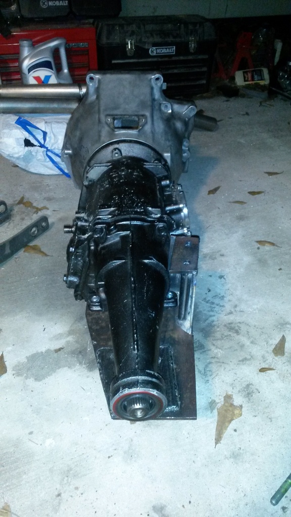
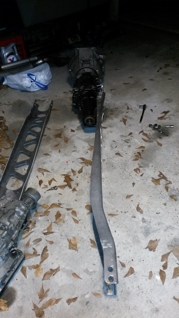
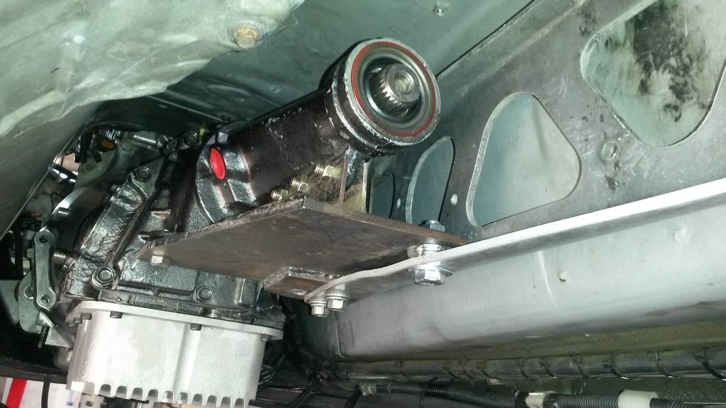
It's in the car, and it fits. I adjusted the PPF up a bit on the front and got the driveshaft angles for the trans and diff the same as before.
Actually not quite as easy to install the PPF as I'd hoped. I have to remove the bolts, but keep the bracket in place (and tilt the back of it down a bit) to slide the PPF onto the trans. Mazda has more slop on the PPF to trans connection, I only left .040" clearance and that isn't enough to get the PPF on in my car without tilting my bracket down to line it up. Should have done it how mazda did, I see why they have it loose now.
Overall looks good. Got the last bolt ready to go, just gotta buy some material or washers or something to make a 0.400" spacer to fill the gap between the adapter and PPF.
Also worth noting, the threads in the trans were crap where the two big bolts for the C4 trans mount go (this case is probably 40 years old) so I helicoiled those so I won't have to worry about that. I swear I'm going to helicoil every fastener on my next engine build, I love how well they work.
Driveshaft parts are ordered, going to weld the C4 stuff onto the front of the mazda driveshaft.
Tomorrow I'll make and install the last spacer. Then probably start working on front turbo stuff.
Reply
0
0

Thread Starter
Elite Member
iTrader: (16)
Joined: Aug 2007
Posts: 9,406
Total Cats: 559
From: Houston, TX
I have not seen it.
Trans is in. I started messing with the front turbo setup. Cut the water inlet shorter, just gotta weld it back together. I hammered a small dent in runner 2 on the manifold so it won't hit the block. Didn't take much to make that problem go away.
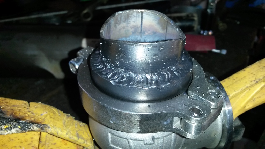
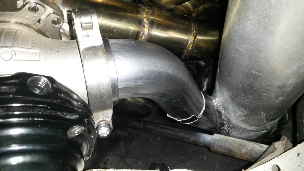
Built a new downpipe. It's only 2 bends, looks sweet and should flow great.
The wastegate I bought is junk, so ordered a different one. Waiting on it for the next few days.
Torque converter is built and was mailed out yesterday, should have it soon. Hope it fits right the first time and works well!
Trans is in. I started messing with the front turbo setup. Cut the water inlet shorter, just gotta weld it back together. I hammered a small dent in runner 2 on the manifold so it won't hit the block. Didn't take much to make that problem go away.
Built a new downpipe. It's only 2 bends, looks sweet and should flow great.
The wastegate I bought is junk, so ordered a different one. Waiting on it for the next few days.
Torque converter is built and was mailed out yesterday, should have it soon. Hope it fits right the first time and works well!


Reply
1
1
GM uses a long torque arm and a transmission crossmember. Something to think about if you find under testing the PPF is not rigid enough for hard launches. Perhaps a cross member where the PPF attaches to the transmission?
Anyways, very impressive work you are doing. I contribute your inspiration for me getting after it on my project.
Anyways, very impressive work you are doing. I contribute your inspiration for me getting after it on my project.
Reply
0
0

Thread Starter
Elite Member
iTrader: (16)
Joined: Aug 2007
Posts: 9,406
Total Cats: 559
From: Houston, TX
GM uses a long torque arm and a transmission crossmember. Something to think about if you find under testing the PPF is not rigid enough for hard launches. Perhaps a cross member where the PPF attaches to the transmission?
Anyways, very impressive work you are doing. I contribute your inspiration for me getting after it on my project.
Anyways, very impressive work you are doing. I contribute your inspiration for me getting after it on my project.
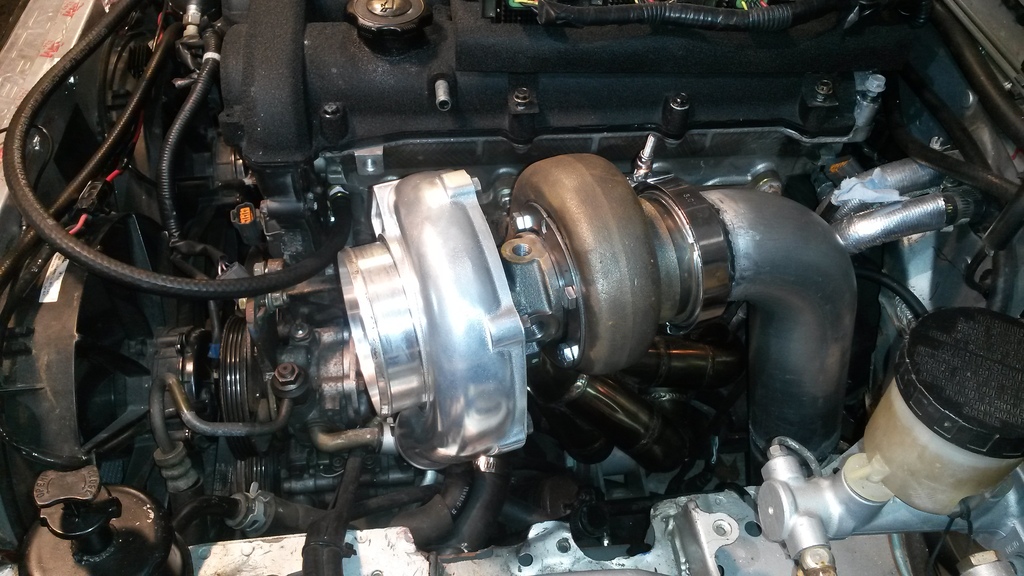
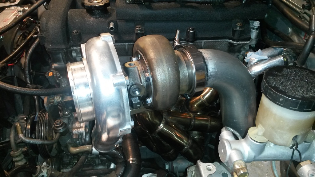
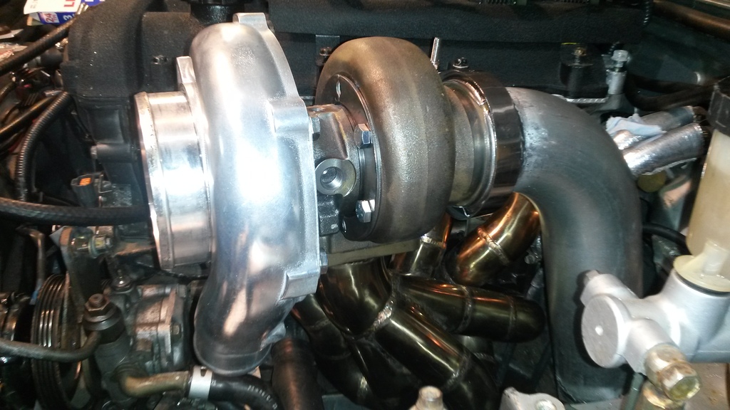
I think the pics make the turbo look bigger than it actually is. But it does look way cooler than a cast manifold setup.
Reply
0
0
Thread Starter
Elite Member
iTrader: (16)
Joined: Aug 2007
Posts: 9,406
Total Cats: 559
From: Houston, TX
Converter is here, looks sweet. Forgot to take a pic of it, will do that next time I take pics.
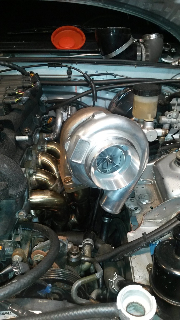
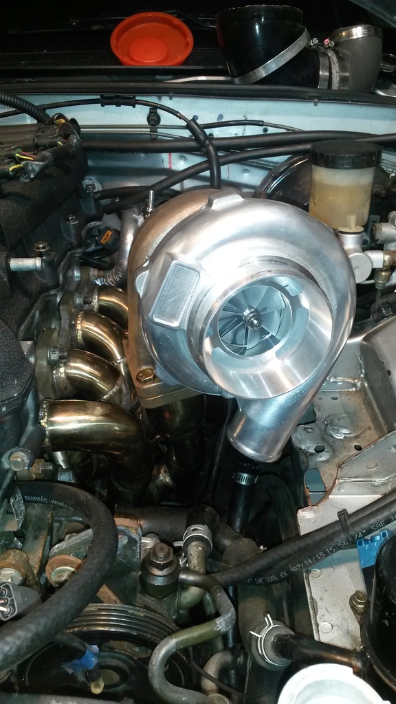
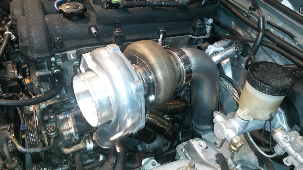
Got the turbo setup coming together. Added a wastegate port to the manifold, shortened the water inlet pipe, built a dump tube that ties into downpipe, made a gasket for turbo (i know, but flange was warped and no easy way to surface it right now), other stuff I'm sure. Pics.
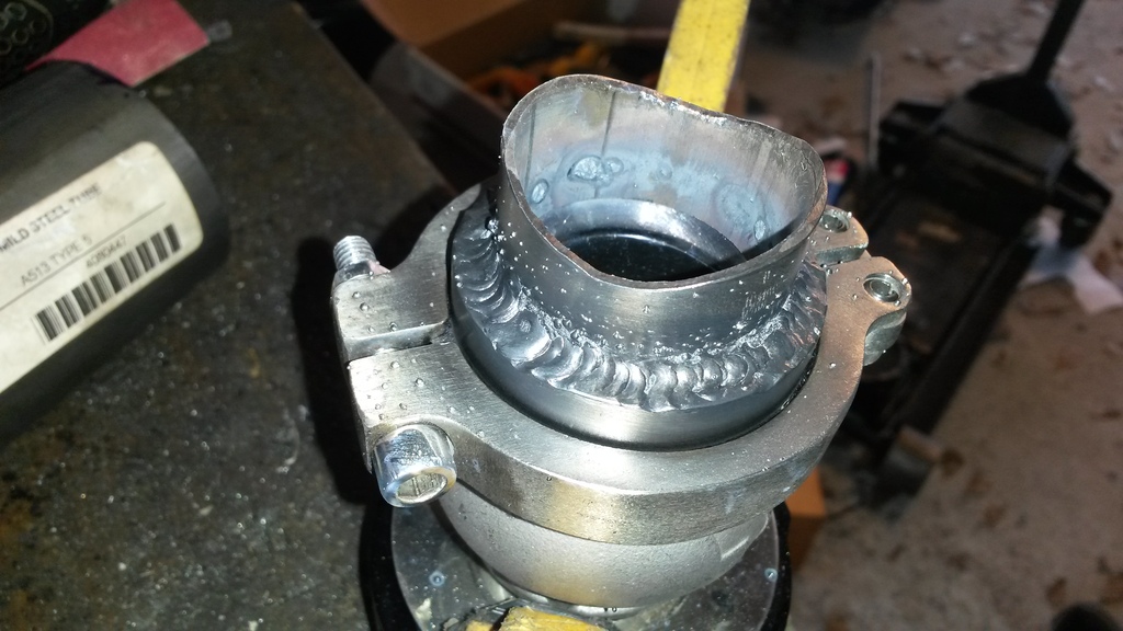
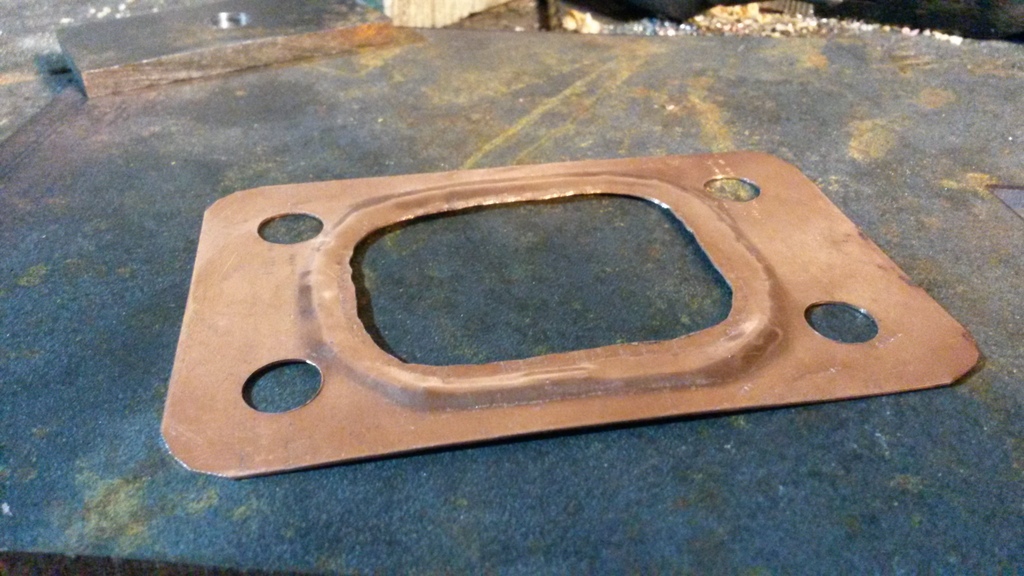
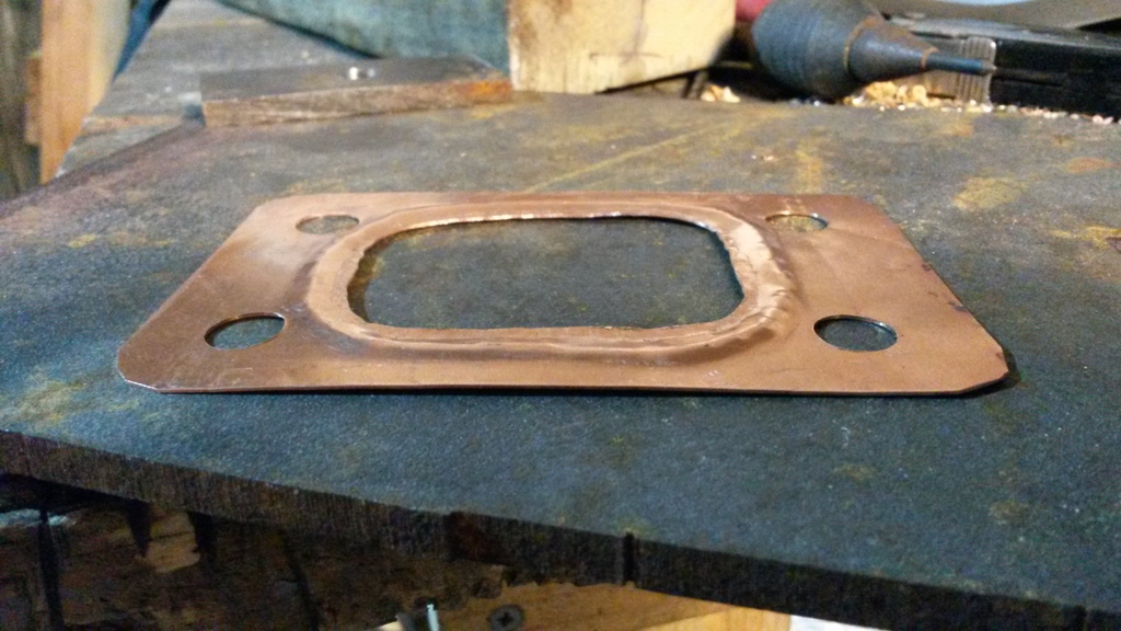
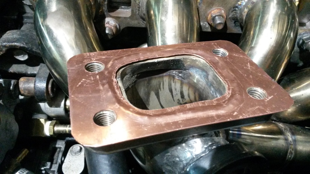
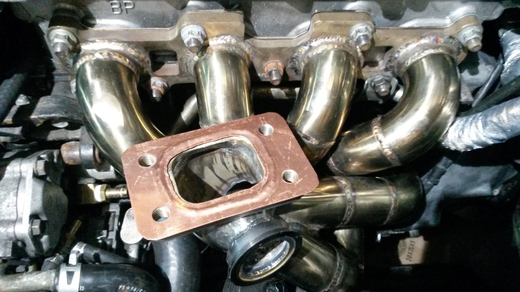
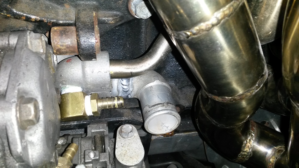
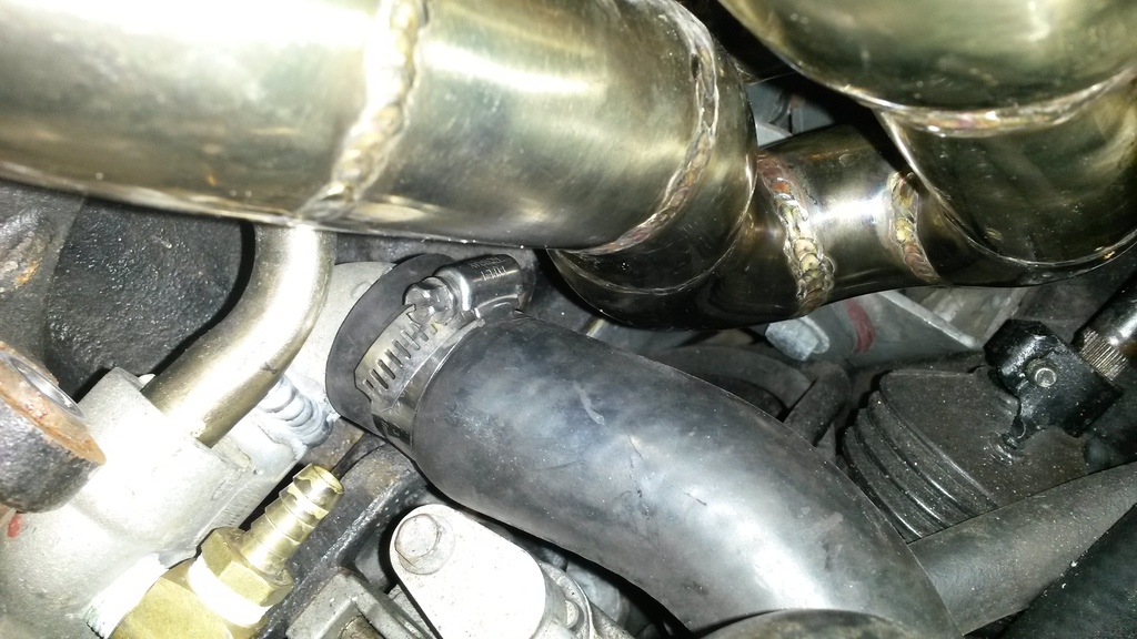
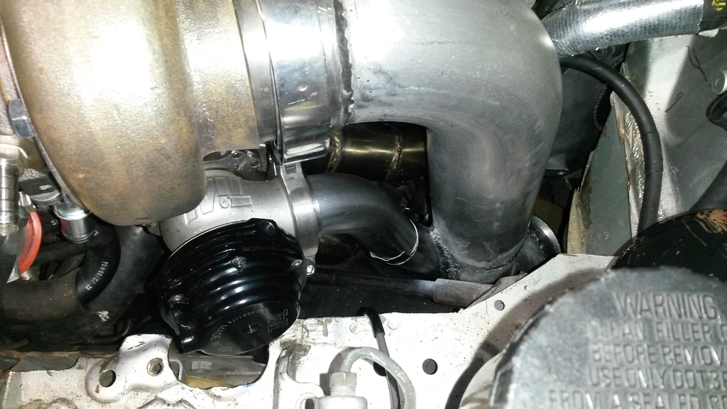
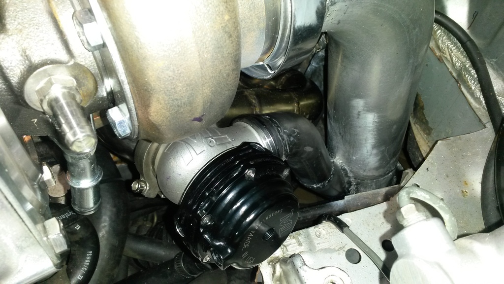
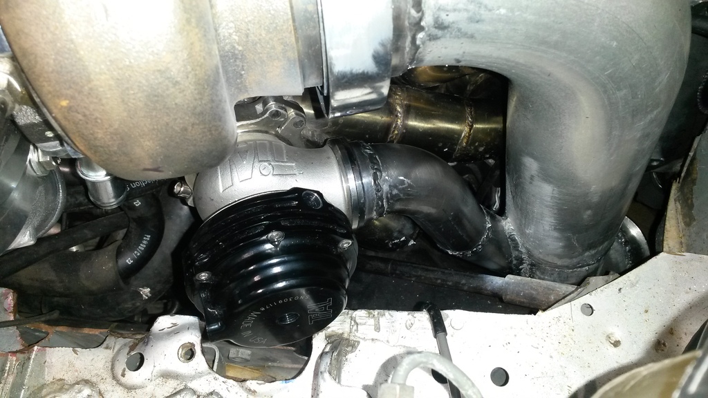
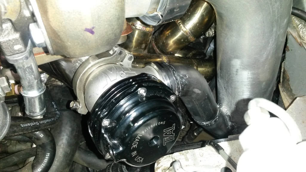
Got the turbo setup coming together. Added a wastegate port to the manifold, shortened the water inlet pipe, built a dump tube that ties into downpipe, made a gasket for turbo (i know, but flange was warped and no easy way to surface it right now), other stuff I'm sure. Pics.


Reply
1
1


