When you click on links to various merchants on this site and make a purchase, this can result in this site earning a commission. Affiliate programs and affiliations include, but are not limited to, the eBay Partner Network.
For years and years, dating back to at least 2013, I've wanted to build a warning system for the car. A system that monitors all the basics, and alerts me if anything bad happens. I started to design a system in 2013 or 2014 but never finished the design, never built anything. Thought about it a few times since but again, never built anything serious.
So now, after at least 7 years in the making, I'm finally going to build it!
I'm expecting this to be a bit of a project, something that is going to start now, but will be slower development and likely wont' be on the car until this winter. Will be a weekend project kind of thing.
Specs are still in development, but I'll post a summary of the idea below.
Monitors many sensors in realtime
Range checks the sensors, sets a Green/Yellow/Red light depending on if everything is good/not great/bad. From the drivers seat, if the light is green, I'm good.
Ideally, also displays state of each sensor with a green/yellow/red light. Or even better, an LCD digital display that has a readout for every sensor and changes background color of that sensor based on range checking.
Has enough inputs/outputs to monitor all the things.
Supports analog signals, digital signals, EGT, etc.
Has basic logical programming so I can change range check conditions based on other sensors. Example, AFR range check varies with MAP, Voltage check varies with RPM, etc.
Works with CHEAP AND COMMONLY AVAILABLE SENSORS. Nothing that cost more than 20 bucks/sensor. I don't want this to be expensive.
All sensors are PNP for easy wiring.
Calibration of sensors is easy.
Probably some flavor of Arduino for MCU since they are easy to use and readily available. Custom board to interface the MCU with input filters required for sensors.
Below is a list of all the things I'm planning to have this system monitor.
WBO2_1
WBO2_2
MAP
Oil PSI
Coolant PSI
Fuel PSI
Crankcase PSI
Oil Temp
Coolant Temp
Trans Temp
EGT_cyl_1
EGT_cyl_2
EGT_cyl_3
EGT_cyl_4
EGT_pre_turbine
EGT_post_turbine
Turbo_rpm
Fuel_pump_1_current
Fuel_pump_2_current
Battery_voltage
The above allows me to error check the WBO2's against each other in case one fails or drifts out of calibration (this has happened several times in the past). Map lets me warn against overboost (rare problem). Oil psi is obvious. Coolant psi for coolant leak (has happened a couple times) fuel psi for pump failure (has happened 4 times), pump cavitation, dirty fuel filter, anything that causes low fuel pressure, crankcase pressure for sad engine (few of those...) , oil temp is obvious, coolant temp obvious (has happened when lost coolant in the past), trans temp obvious, EGT1 through EGT4 to compare how the cylinders are running relative to each other. Pre/Post turbine to see EGTs into and out of turbo for turbo reliability and possibly turbo efficiency improvements from exhaust changes. Turbo RPM for turbo reliability(killed 3 front turbos in a row from overspeed), can warn if boost leak happens, fuel pump current in case a pump fails (this has happened before), battery voltage for alternator performance under high currents (have had issues in the past)
It will be awesome when I can drive and race and not worry about any of the above, knowing it's all being watched for me and if anything happens, it will tell me immediately.
If you can think of anything important a race car should have on that list, let me know!
Will post some pics of this as development progresses. Right now it's mostly just concepts, specs, what parts to use, etc. I found a touchscreen I ordered, hoping it's easy enough to get working so I can a fancy display!
Are you going to be relying on your ability to notice a light changing from green to yellow/red in the middle of a pass or will you be triggering a limp mode on the megasquirt?
Glad you're back pat. This is still my favorite build thread on the forum.
Are you going to be relying on your ability to notice a light changing from green to yellow/red in the middle of a pass or will you be triggering a limp mode on the megasquirt?
Glad you're back pat. This is still my favorite build thread on the forum.
Glad to be back, and happy this is your favorite!
It will be connected to the ECU for sure. I guess I should have mentioned that! I don't know the details yet, but the typical reduce boost, reduce timing strategies would be used at a minimum.
One thing I thought of I may add, is a fire detection system. I've blown an engine a couple times where I thought there was a fire from all the smoke. Luckily there was no fire. If I could do that cheap, I might add it. Looking into how airplane engines detect fires RN.
I'm using a Nextion display on the arduino based dash/monitor/etc that I have in my car. It's great from a simplicity standpoint because it's got its own microcontroller -- you generate a screen template using a Windows app, upload that to the nextion, and then you can drive it using serial commands from the Arduino. This offloads all the heavy graphics stuff that the Arduino doesn't really have the horsepower to drive. The downside is that they aren't available in an anti-glare model, which means that at certain angles in bright sunlight it can be quite difficult to read.
I'd also want multiple IAT sensors.
At air intake =ambient
At compressor discharge
Post intercooler (at throttle body)
I'd also want Turbine inlet pressure.
Might be nice to have AC system low and high side pressure sensors...
I designed something similar, built a decent amount of it, even developed my own wireless BT network out of ebay nodes so I wouldn't have to run wires everywhere. Ultimately shrunk it down to 27 additional channels + 4 EGT. The wiring was still a total PITA. I bailed on the BT net, getting all of the point to point pairing to reliable and automated turned out to be more work than it was worth.
Unfortunately, I found the idea of the whole thing was a lot better than the usefulness. You are really limited in the number of fields you can log to SD, and TS logging is really kinda sucky. Plus, you are limited to only 16 sensor channels in the MS, you can access more channels via CAN, but you can't do anything with them other than log via TS or display on a dash. Even with CAN I think you can only get to like 24 channels. I did discover that you can map to EGT which ~kinda~ gets you additional sensor channels. You can at least log them to SD. Other ECUs may not have the same limitations.
It is really handy to have acess to all sorts of crazy data when I want to look at it. For example, I can perform real-time calculation on the efficiencies for both compressors and their associated heat exchangers. I know the pressure drops across both the fuel and oil filters, and I can even display them (as well as other fluid pressures) through the stock OP gauge in the instrument cluster via rotary switch in the console.
It was a fun project, but I don't think I will do it again. The wiring, seriously, the wiring.
I've built something using a Teensy3.2 similar to what you're looking to do that supports:
* 1x or 2x 128x64 OLEDs to display data from the MS (you can cycle between display screens using a pushbutton and holding it for a few seconds resets the Peak values on the "Peaks" screens)
* 4x Temperature sensors
* 2x Pressure sensors
* 1x Gyro/Accelerometer
* 1x 10Hz GPS (testing this is how I discovered that the MS wasn't handling Southern latitudes at all; see https://www.msextra.com/forums/viewt...?f=131&t=67777 - now fixed in latest FW)
* 1x Innovate Wideband Serial O2 (no more need for the TSE WB02 module)
* 3x Digital input switches (1 used to control OLED displays)
* 1x CAN bus to communicate with the MS
* 1x Fuel level input
My DIY PCB, 4-layer board using ExpressPCB Plus (don't even try all this using a breadboard, it'll just end up a jumbled mass of wires):
- I used an MCP3008 for the A->D conversion since all sensor inputs are 5V but the Teensy3.2 simply clips anything over 3.3V to 3.3V :(
Here's examples of the OLEDs (these are blue OLEDs, the white ones actually look better with my retro cluster): Example OLED displays showing 3 Lines
Example displays showing 4 lines each (smaller font than above)
The OLEDs are mounted using my DIY 3D printed housings that fit into the existing NB cluster. Here's the digital button that controls the OLED displays:
Load-testing setup (the Teensy3.2 and circuitry is housed in the small black aluminium extruded box in the top left; the Arduino UNO is being used to simulate Innovate serial data):
Currently developing the next generation of this board, improvements:
* R3, R4 and R5 not needed on Teensy for digital inputs, all pins on Teensy's have built-in pullups that can be enabled in software
* built-in 6-36V->5V converter so can simply be powered by 12V input (additional/external 12V->5V component not required)
* built-in MAX232 chip so external component not required for Innovate Serial->TTL
* get rid of MCP3008 and simply use voltage dividers to scale analog 0-5V signals to 0-3.3V (preserves full 10-bit digital input range 0-1023)
* add missing fuel pull-up resistor
* simpler socket (current one is too hard to add some wires initially and others at a later date without destroying the plug)
As Ted75zcar pointed out, wiring in "all the things" is a bit of a nightmare and not necessarily as useful as you may think so manage your requirements accordingly, "everything" is too much.
I require 36x socket pins and 2x pins for power+GND for my needs - when fully populated, this is a LOT of wires (as you can see in the photo above).
For a live warning system, it's simpler and easier to read/notice a SINGLE+LARGE warning rather than have multiple ones for you to constantly monitor so consider just using a single display that can write what the highest priority warning is - post analysis of log files can reveal what other issues are present.
My system maintains peak values that can be seen on the "PEAKS" display - this is useful because you don't have to constantly be looking at the gauge to see what the maximum value is/was and is handy to look at after a session to quickly see if you had any issues (in which case you analyse the MS log files).
With regard to "Works with CHEAP AND COMMONLY AVAILABLE SENSORS. Nothing that cost more than 20 bucks/sensor. I don't want this to be expensive." - "20 buck" pressure sensors won't suffice (unless you can score decent ones from a wrecker)
I designed something similar, built a decent amount of it, even developed my own wireless BT network out of ebay nodes so I wouldn't have to run wires everywhere. Ultimately shrunk it down to 27 additional channels + 4 EGT. The wiring was still a total PITA. I bailed on the BT net, getting all of the point to point pairing to reliable and automated turned out to be more work than it was worth.
:
Agree that BT is a pain in the ****, stick to a wired solution (the latest Android 10 update apparently screws up BT on some devices too, requiring them to be started in a specific order).
I created an Android App, MsTrackIt, with a serial interface to the MS which works well.
When I added the Bluetooth interface, it worked on the bench but in a vehicle it dropped out continuously so I never released the BT version, it just wasn't reliable enough no matter what BT-Serial adaptor I used so would have led to multiple complaints.
I assume Android Apps like Torque suffer similar dropouts but hide/mask them better.
In hindsight I now wonder if I was actually surpassing BT's bandwidth limit since my App required a lot of data and the bench testing probably generated it slower than the MS could.
I'm using a Nextion display on the arduino based dash/monitor/etc that I have in my car. It's great from a simplicity standpoint because it's got its own microcontroller -- you generate a screen template using a Windows app, upload that to the nextion, and then you can drive it using serial commands from the Arduino. This offloads all the heavy graphics stuff that the Arduino doesn't really have the horsepower to drive. The downside is that they aren't available in an anti-glare model, which means that at certain angles in bright sunlight it can be quite difficult to read.
--Ian
Thanks for the info. I actually did end up with a Nextion display! I had previously seen your display a while back, I never knew or realized it was a Nextion.
Just a thought, but I wonder if you can buy an anti-glare piece to put over the display? Might be an option.
Originally Posted by technicalninja
I'd also want multiple IAT sensors.
At air intake =ambient
At compressor discharge
Post intercooler (at throttle body)
I'd also want Turbine inlet pressure.
Might be nice to have AC system low and high side pressure sensors...
Some of these would be nice, but more from a datalogging and efficiency standpoint than a "uh oh, something bad just happened".
But that is something I need to consider. My main thing was to use this to look for problems, not to improve the system through analyzing data.
Originally Posted by Ted75zcar
I designed something similar, built a decent amount of it, even developed my own wireless BT network out of ebay nodes so I wouldn't have to run wires everywhere. Ultimately shrunk it down to 27 additional channels + 4 EGT. The wiring was still a total PITA. I bailed on the BT net, getting all of the point to point pairing to reliable and automated turned out to be more work than it was worth.
Unfortunately, I found the idea of the whole thing was a lot better than the usefulness. You are really limited in the number of fields you can log to SD, and TS logging is really kinda sucky. Plus, you are limited to only 16 sensor channels in the MS, you can access more channels via CAN, but you can't do anything with them other than log via TS or display on a dash. Even with CAN I think you can only get to like 24 channels. I did discover that you can map to EGT which ~kinda~ gets you additional sensor channels. You can at least log them to SD. Other ECUs may not have the same limitations.
It is really handy to have acess to all sorts of crazy data when I want to look at it. For example, I can perform real-time calculation on the efficiencies for both compressors and their associated heat exchangers. I know the pressure drops across both the fuel and oil filters, and I can even display them (as well as other fluid pressures) through the stock OP gauge in the instrument cluster via rotary switch in the console.
It was a fun project, but I don't think I will do it again. The wiring, seriously, the wiring.
Oh, and lots of 5V current.
Thanks for the info! I now remember you posting about the BT nodes a while back, I had forgetten about that.
I'm was already thinking that this could turn into a mess, with too many things.
For example, if I really wanted to make this simple, I'd just do AFR. That has went out of range many times for 10 different reasons. It would be the most valueable thing to track in a warning system, and I can easily justify the couple wires it would take to read an WBO2 sensor.
I will give this some thought. I don't want a mess.
I will be able to run code to do range checking, etc, so not limited by MS's ability there. I'll have to review your thread and read up about what you did.
Originally Posted by Lokiel
I've built something using a Teensy3.2 similar to what you're looking to do that supports:
* 1x or 2x 128x64 OLEDs to display data from the MS (you can cycle between display screens using a pushbutton and holding it for a few seconds resets the Peak values on the "Peaks" screens)
* 4x Temperature sensors
* 2x Pressure sensors
* 1x Gyro/Accelerometer
* 1x 10Hz GPS (testing this is how I discovered that the MS wasn't handling Southern latitudes at all; see https://www.msextra.com/forums/viewt...?f=131&t=67777 - now fixed in latest FW)
* 1x Innovate Wideband Serial O2 (no more need for the TSE WB02 module)
* 3x Digital input switches (1 used to control OLED displays)
* 1x CAN bus to communicate with the MS
* 1x Fuel level input
My DIY PCB, 4-layer board using ExpressPCB Plus (don't even try all this using a breadboard, it'll just end up a jumbled mass of wires):
- I used an MCP3008 for the A->D conversion since all sensor inputs are 5V but the Teensy3.2 simply clips anything over 3.3V to 3.3V :(
Here's examples of the OLEDs (these are blue OLEDs, the white ones actually look better with my retro cluster): Example OLED displays showing 3 Lines
Example displays showing 4 lines each (smaller font than above)
The OLEDs are mounted using my DIY 3D printed housings that fit into the existing NB cluster. Here's the digital button that controls the OLED displays:
Load-testing setup (the Teensy3.2 and circuitry is housed in the small black aluminium extruded box in the top left; the Arduino UNO is being used to simulate Innovate serial data):
Currently developing the next generation of this board, improvements:
* R3, R4 and R5 not needed on Teensy for digital inputs, all pins on Teensy's have built-in pullups that can be enabled in software
* built-in 6-36V->5V converter so can simply be powered by 12V input (additional/external 12V->5V component not required)
* built-in MAX232 chip so external component not required for Innovate Serial->TTL
* get rid of MCP3008 and simply use voltage dividers to scale analog 0-5V signals to 0-3.3V (preserves full 10-bit digital input range 0-1023)
* add missing fuel pull-up resistor
* simpler socket (current one is too hard to add some wires initially and others at a later date without destroying the plug)
As Ted75zcar pointed out, wiring in "all the things" is a bit of a nightmare and not necessarily as useful as you may think so manage your requirements accordingly, "everything" is too much.
I require 36x socket pins and 2x pins for power+GND for my needs - when fully populated, this is a LOT of wires (as you can see in the photo above).
For a live warning system, it's simpler and easier to read/notice a SINGLE+LARGE warning rather than have multiple ones for you to constantly monitor so consider just using a single display that can write what the highest priority warning is - post analysis of log files can reveal what other issues are present.
My system maintains peak values that can be seen on the "PEAKS" display - this is useful because you don't have to constantly be looking at the gauge to see what the maximum value is/was and is handy to look at after a session to quickly see if you had any issues (in which case you analyse the MS log files).
With regard to "Works with CHEAP AND COMMONLY AVAILABLE SENSORS. Nothing that cost more than 20 bucks/sensor. I don't want this to be expensive." - "20 buck" pressure sensors won't suffice (unless you can score decent ones from a wrecker)
First off, that gauge cluster turned out really nice. Wow! That's a really clean setup.
I do have a question about the 20 dollar pressure sensors. What do you think about them wont' work?
I bought some a while back, and my experience was that the one that does fuel pressure has worked fine, the one that does oil temp fails with high temps, basically as the motor gets good and warmed up, it dies. Once it cools down, it comes back. Was your results similar?
I was thinking about buying a few different cheap pressure sensors, and then test them in an oven I have and see if any of them maintain their functionality and accuracy with temp. I do like the idea of using OEM pressure sensors if I can find some that are affordable and hopefully not too bulky.
I have a good software for PCB layout, so that won't be a problem. Will be similar to what you did, likely a 4 layer as well.
One thing I need to look into is wiring. I see that is a common concern. I will need to see what I can come up with to make that as simple/easy as possible.
$20 ebay pressure sensors wander hard with heat. Useless garbage. I'd be interested to see if you find any linear temperature offset, never thought to try.
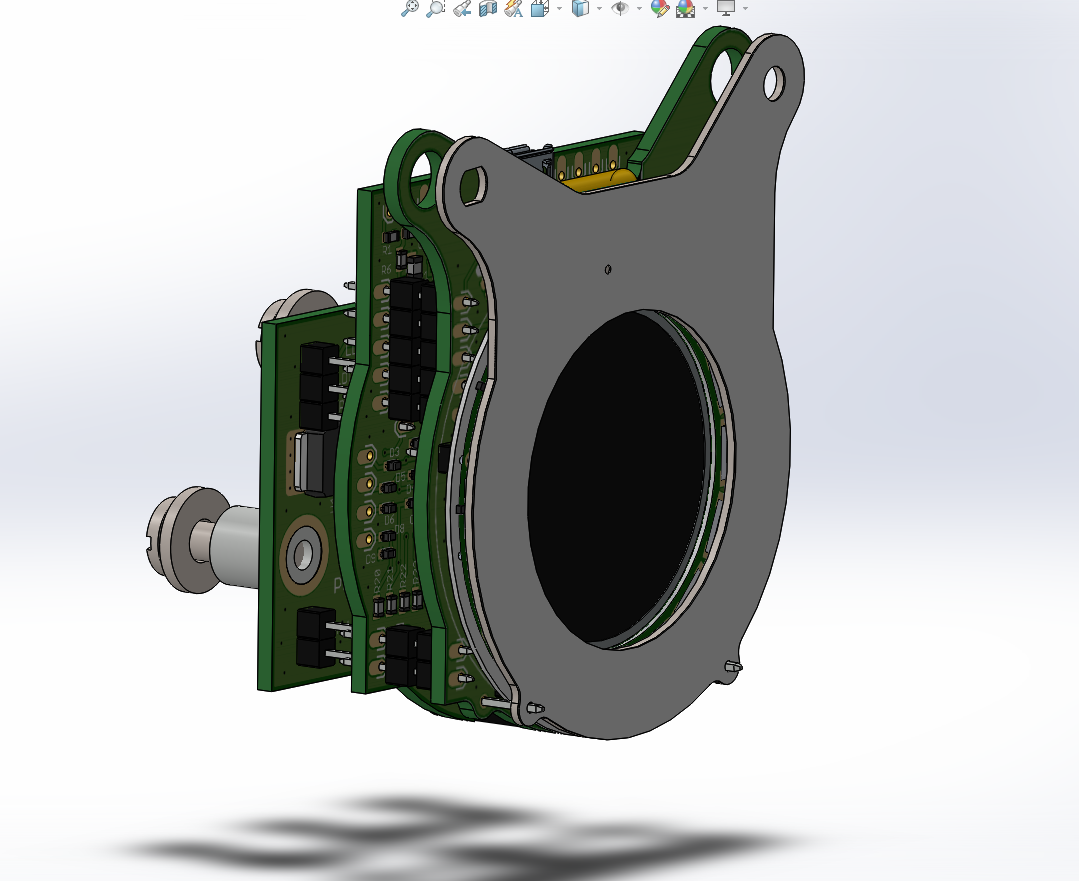
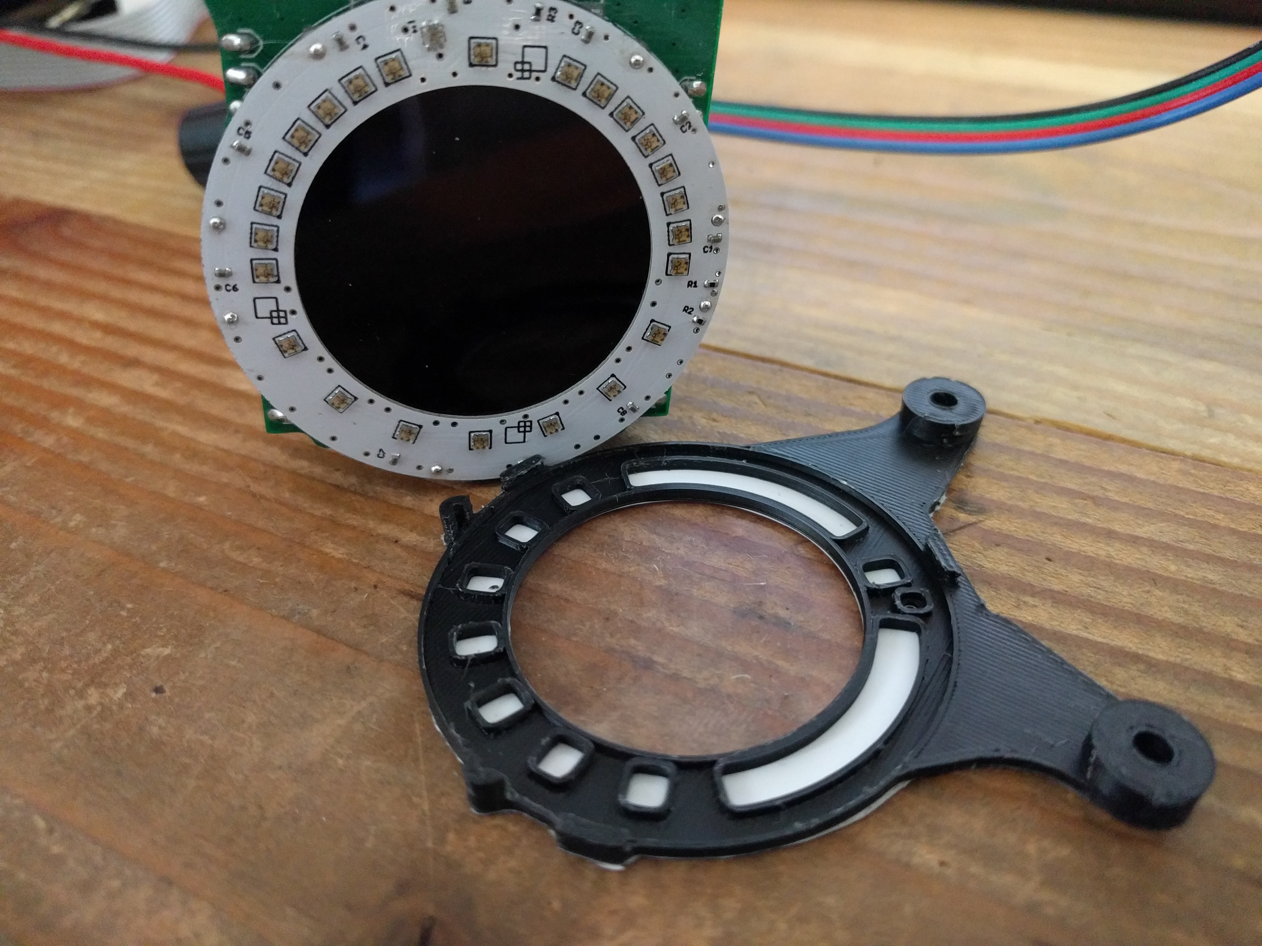
Here's my take on a bunch of quickly visible warning lights.
$20 ebay pressure sensors wander hard with heat. Useless garbage. I'd be interested to see if you find any linear temperature offset, never thought to try.
I noted the idle pressure value logged when I first installed the eBay oil pressure gauge was significantly different to the value reported after a couple of weeks of week-end testing (ie. more than a few digits, not just minor decimal points).
Google searches confirmed what deezum suggested above and that their calibration degrades quickly, something you don't want in a gauge on a track car.
I use Honeywell pressure sensors, expensive but reliable.
$20 ebay pressure sensors wander hard with heat. Useless garbage. I'd be interested to see if you find any linear temperature offset, never thought to try.
Here's my take on a bunch of quickly visible warning lights.
...
I made my own LED ring, added a light sensor to automatically dim the LEDs.
...
That is quite impressive! Pretty slick setup.
I was thinking I'd buy a few various cheap sensors, and test them, see if any work ok. The cheap ones I bought a few years ago seem to fail with temperature.
Originally Posted by Lokiel
I noted the idle pressure value logged when I first installed the eBay oil pressure gauge was significantly different to the value reported after a couple of weeks of week-end testing (ie. more than a few digits, not just minor decimal points).
Google searches confirmed what deezum suggested above and that their calibration degrades quickly, something you don't want in a gauge on a track car.
I use Honeywell pressure sensors, expensive but reliable.
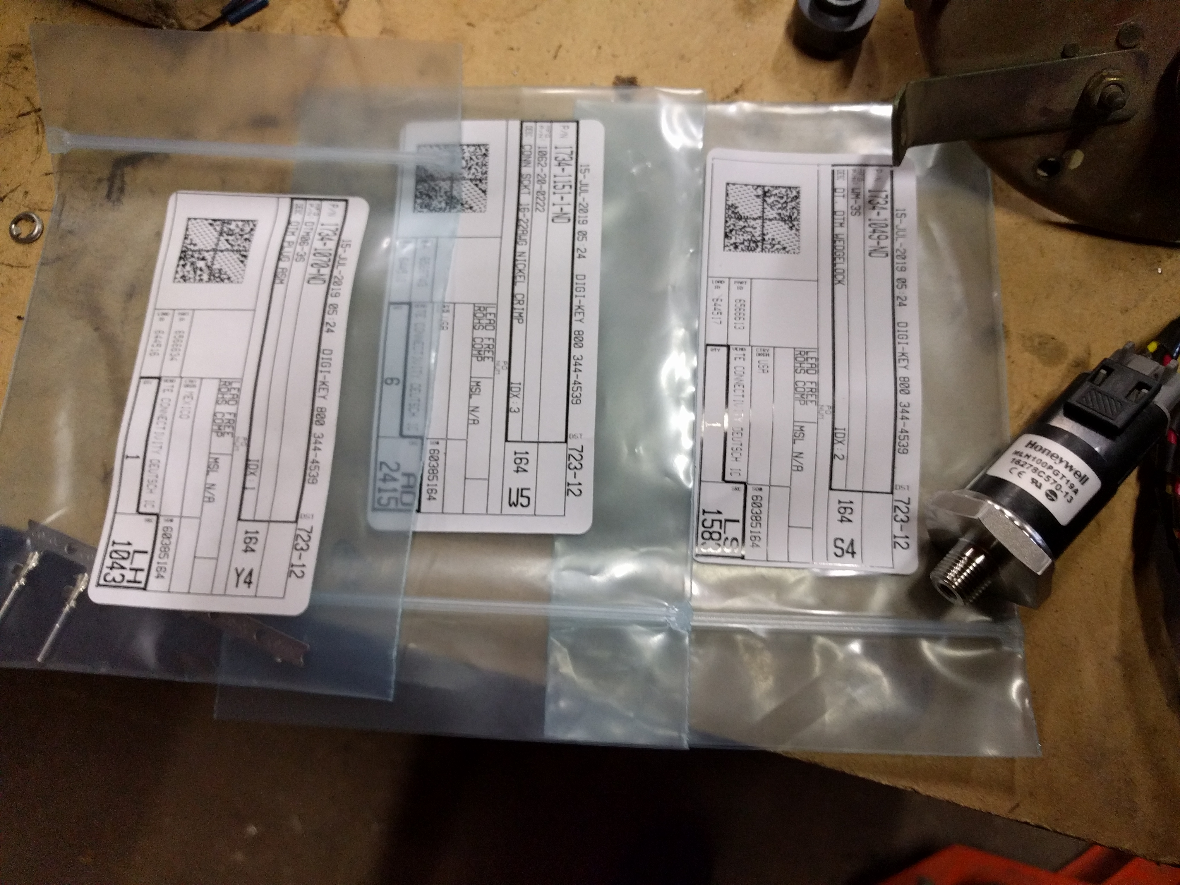
What honeywell sensor are you using? Where did you buy it from?
That's a 1/8" BSP sensor that fits in the stock location and doesn't mess up with heat, and I think you can get them from Arrow. I think I've found a few that are actually rated for fuel but most are 3+ months out and custom order. I think they are MIP series, or at least the ones rated for fuel. Supposed to work well with coolant, too.
My ebay fuel pressure sensor wanders over 20psi after a 30 minute drive, waste of money. If someone has a good source for a rated for fuel honeywell in 1/8" NPT, I'd sure like to see!
I have had better experience with the junk ebay stuff, I don't see nearly as much degradation as others, maybe just lucky?
That said, when I replace a transducer moving forward it will be with a honeywell.
Mouser looks to have stock on several of the honeywell sensors, not sure if any of them are what you are looking for. I looked at one, it was rated for engine oil and hydraulic fluid, rated to 257F.
Those are 2% FS @ 125*C. $43.67 each, bit cheaper if I buy 5 or 10. Hmm. More than I was budgeting, but that's not the 200+ that I was seeing last time I looked up honeywell sensors. I can swing 43/sensor.
Those should be in stock in about a month. 100 psi, MIP series, 1/4 NPT, +/- 0.75% FS at 125*C. 10 of those 35.61 each. So 356 bucks I can measure 10 pressures up to 100 PSI. Could be a good option.
Thanks for mentioning the honeywell sensors! I had no idea they were available at these prices.
 07-14-2020, 01:11 AM

 0
0