Pat's Ebay Turbo Compound Boost Build

 08-09-2020, 02:21 PM
#1662

For 15x11s I think custom is your only way. I had Keizers, I know someone got Bogarts done. I forget what everyone else has. I really doubt a 275 street tire is as wide as a 275 hoosier so you're probably fine with 15x10s. To fit them you need to do the following, cut fenders and roll/hammer rear fender inner lining out/up, hammer front wheel well pinch weld flat, trim NB style shock mount flush where the tire hits or use flat billet style mounts, cut front bumper to fit. Hammer in wheel well where required. Adjust bump stop length/ I suggest you remove the spring from the shock but leave teh bump stop in while you figure this out so you figure out how much longer you need to make your bump stops once you get tired of hammering and trimming.

Reply
 1
1

1
08-09-2020, 02:59 PM
#1663
Elite Member
Thread Starter
iTrader: (16)
Join Date: Aug 2007
Location: Houston, TX
Posts: 9,297
Total Cats: 477
For now, I got it doing sweeps from 0-100-0 with a spal fan, and two 12V ebay fans. Ordered a current meter, will be here tomorrow.
My Kill-A-What meter shows I'm pulling 530W from the 120V wire that feeds my SMPS. If it's 90% efficient, that's 477W to the fans. I'm measuring 14.59V at full load with my Fluke, so that works out to 32.69 Amps into the fans.
I've been looking for a supply that will do 15V and all the amps, so far not finding much that isn't a thousand dollars. I did find a 12V one that will do lots of amps, but it isn't adjustable. Would really like to do all my testing at 15V.
Reply
0
0
08-09-2020, 03:24 PM
#1664
Elite Member
Thread Starter
iTrader: (16)
Join Date: Aug 2007
Location: Houston, TX
Posts: 9,297
Total Cats: 477
Found this guy:
Says it's adjustable to 15V and rated to 50A. So technically will work, though I would like to have some headroom as I want my fan controller to be rated to 50A, but tested higher. The gauge on the front goes to 16V and 64A so it may have some headroom.
Says it's adjustable to 15V and rated to 50A. So technically will work, though I would like to have some headroom as I want my fan controller to be rated to 50A, but tested higher. The gauge on the front goes to 16V and 64A so it may have some headroom.
Reply
0
0
08-10-2020, 01:37 AM
#1665
Elite Member
Thread Starter
iTrader: (16)
Join Date: Aug 2007
Location: Houston, TX
Posts: 9,297
Total Cats: 477
Small update!
Been looking into wheels/tires. Seems a 10" wheel and 245, there are a couple wheel options in stock, and a few tire options from 200 and 100 tread wear, and I think a couple 40 treadwear options.
I'm wondering, is going to an 11" and 275 worth it? I ask, because it will cost a lot more. I can't find any 15x11 wheels for one. And I'd have to wait for the new 275 tire that's supposed to be coming soon.
In other news, I have made a small amount of progress on my fan controller. Well, sort of. I'm developing a different part for a friends car, and while it's not a fan controller, it does have the high power electronics on it that I may use for my fan controller if they prove reliable in that environment.
I ran it doing about 4kHz PWM, sweeping from 0% to 100% and back to 0% in a 30second loop, running a large SPAL fan that pulls about 22A in free air and it seems to do that OK. Also wired in a large DC motor for an electric power steering pump and a 12V headlight bulb to add some extra load and that went ok. (about 35A and two inductive loads)
Just ordered another SPAL fan and will do more testing having it drive a pair of large spal fans, and an electric motor and headlight bulb. My goal is to get it to drive a 50A load without issue.
So far the biggest hurdle seems to be the edge speed going to my mosfet. I have what I thought was a very beefy gate driver, but still seeing slower than hoped for V/ns on the input of the FET.
Also need to buy a large amp meter, and a larger power supply for further testing. I fried this 30A supply once already and repaired it, need a bigger one.
Been running this ~32A load doing sweeps for a total of 5 hours so far without issue.
Regarding the V/ns issue with the gate driver, I think my return path to ground was too skimpy. Next board, I'm going to beef that up, see if it helps. Also moved the bypass cap a bit closer to the driver, and ran larger traces on the power wires to get low voltage drop in/out of the gate driver.
Reply
0
0
08-12-2020, 02:17 AM
#1666
Elite Member
Thread Starter
iTrader: (16)
Join Date: Aug 2007
Location: Houston, TX
Posts: 9,297
Total Cats: 477
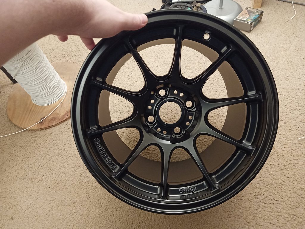
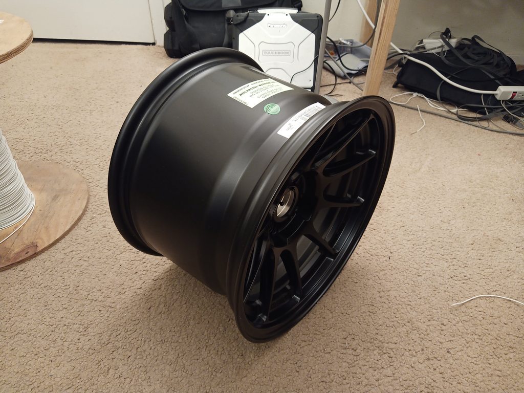
Ordered a set of 245/40/15 RS4's. Looking into wheels/lugs/rings RN, thinking the 15x10 deckagram wheels. Looks like that's about it for 15x10 wheel options?
Reply
0
0
08-12-2020, 09:57 PM
#1667
Elite Member
Thread Starter
iTrader: (16)
Join Date: Aug 2007
Location: Houston, TX
Posts: 9,297
Total Cats: 477
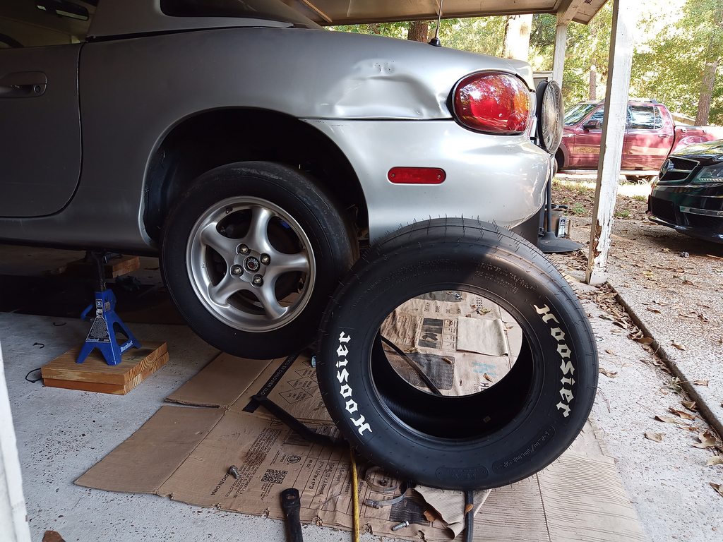
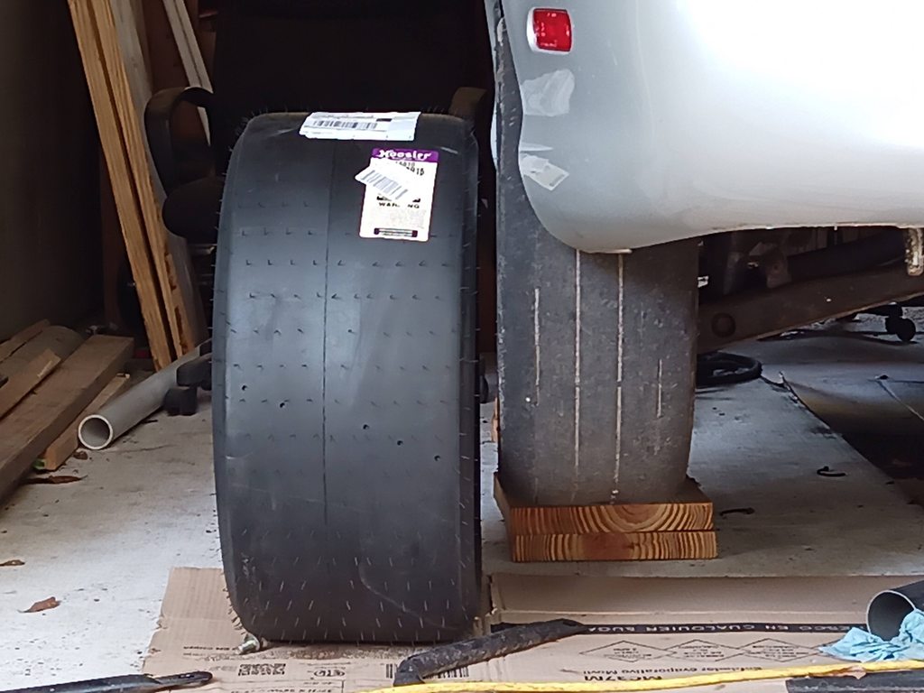
For the drag racing, I'm considering buying these.
https://www.jegs.com/i/Hoosier/522/18810/10002/-1
Those are 26.2" tall, 10.5" tread width, 11.7 section width. Drag Radial.
One reason to run these over a slick is so I can skip tubes. Also not sure if I can run a tube tire without a bead lock.
Not to mention, that's a really beefy tire! I think it would look awesome.
Reply
0
0
08-13-2020, 01:06 AM
#1668
Elite Member
Thread Starter
iTrader: (16)
Join Date: Aug 2007
Location: Houston, TX
Posts: 9,297
Total Cats: 477
Bought the drag radials above, and 6 of the 15x10 deckagram wheels, and lugs and valve stems. Wallet hurts! And not sure how much work it's going to take to get these tires to fit, but if I can get them to fit, it will look awesome. They are almost a foot wide!
Reply
0
0
 08-13-2020, 08:05 PM
#1670
Elite Member
Thread Starter
iTrader: (16)
Join Date: Aug 2007
Location: Houston, TX
Posts: 9,297
Total Cats: 477
I went out and looked at the rear wheel well areas just now. Looks like making these fit is gonna be some work.
Reply
0
0
08-16-2020, 05:34 PM
#1671
Elite Member
Thread Starter
iTrader: (16)
Join Date: Aug 2007
Location: Houston, TX
Posts: 9,297
Total Cats: 477
Update time! Videos of fan testing at bottom!
Got the 245 tires and the 15x10 wheels in. Dang, these wheels are huge. No idea how these are supposed to fit on a miata. I must say, I like the look of these in person more so than in the pictures. Looks like cleaning them is going to suck though, lots of detail in the design.
The 245 tires look good too. Being a 200 tread wear, they aren't as soft as the radials I'm used to. But they are wide, and have tread, and should make a great street tire. Hopefully something I can drive in the rain safely.
Also the ARP studs came in and valve stems. Just waiting on the Hoosiers now, should be here Wednesday.
Fan controller update too!
The 50A 8-15V power supply came in.
I did some testing running the PCB at 30A, PWM controlling 3 fans. Had it running at 4kHz, doing 0-100-0 PWM sweeps over a 30 second cycle. Did that for 6 hours without issue. However, as expected, running it at high duty cycles, the mosfet gets warmer and the flyback diode too.
So I got a new SPAL fan in, and wired it up with the new 50A power supply. Now I can apply a 50-51A load at 15V. This works out to 750 Watts of power! The power supply has a bit of headroom, it appears to drop out a few amps after 50A, but 50, 51, 52, it can maintain 15.00 V.
And it worked... Sort of. It did work, but things were getting hot. So I slowed down the PWM ramp to take 10 min to do a 0-100-0 sweep. Then measured the temp of the mosfet and diode. Well.... Worst case temp on the mosfet was 266�F! The diode got up to 147�F. Terrible. Granted this mosfet is just soldered to the PCB, no attempt at heat sinking to another plane or anything. And no external heat sink.
However, if you don't PWM it, and just turn it on or off, the mosfet thermal performance is fantastic, about 5-10�F above ambient.
I went back over my math on the gate driver and found my mistake. Turns out 10 is not the same as 1. I missed a decimal and it's switching 10x slower than I expected. Using the actual values from the data sheet, I would expect this to take 200ns to switch, and it measured 200-220ns.
With a higher 7.8kHz PWM frequency, this works out to about 99.7% of the time it's on or off, and 0.3% of the time it's switching.
Still looking at parts, but my next iteration will be a board with a few different designs, to try different things.
Probably include two mosfets, and two gate drivers, to share the load between two pairs. Probably same mosfet, but with an attempt at thermal heat sinking to a plane on backside of PCB, and a 10A gate driver instead of a 3A gate driver.
Also going to try a PCB that has multiple 10A gate drivers driving the mosfet to get the switching speed down really low. Probably try designs with 2, 3, and 4 gate drives, just to see how much I can do and where the knee of the gate-drive-amps curve is.
No idea if I'm going to make this work, but the goal is to get the efficiency so good, that it makes very little heat. I'm shooting to have be able to run in a 125�C environment in still air at rated power reliably. It looks like the mosfet meets my specs, but it's not happy with the current switching speeds, so going to see if I can get that fast enough to keep it happy. My day job is with downhole tools for the oilfield, so I'm familiar with high temp and high reliability design requirements.
Here's a couple videos from testing!
Reply
2
2


 08-24-2020, 12:28 AM
#1675
Elite Member
Thread Starter
iTrader: (16)
Join Date: Aug 2007
Location: Houston, TX
Posts: 9,297
Total Cats: 477
I think you guys hit the nail on the head.... Gonna need the hammer!
So, update time! Got a fan update, and another possibility that is in the works.
Been working on the PWM Fan controller. Got some good progress on it. The next design will feature two gate drivers rated at 12A each, in parallel, feeding the same mosfet. I'm expecting this to get the switching times much much quicker than before, hopefully reducing the switching losses to less than 0.1%.
In addition, there will be two sets of these! So four drivers, and two mosfets working to share the load. Also the next board will have considerable effort at thermal management to help spread the heat that is created out where it can dissipate. Also made several smaller improvements here and there.
Got the PCB layout going well, it's routed, all nets are connected. Gonna refine a few things, then thermal stuff, and then order it. Hope to have it ordered this week.
The other thing that's in the works... I'm considering finally getting a shop. Been wanting one forever. I may be getting one soon if I can find one for a fair price. Sure would be nice vs my carport.
Reply
0
0
08-29-2020, 10:33 PM
#1676
Elite Member
Thread Starter
iTrader: (16)
Join Date: Aug 2007
Location: Houston, TX
Posts: 9,297
Total Cats: 477
Update time!
Fan controller board is designed and ordered! I was hoping to get it ordered this week and that happened.
This prototype I'm calling V1. It has two mosfets, two gate drivers per mosfet, and five freewheel diodes. Thermal via stitching between top and bottom to help transfer heat away from the high power components. Traces that carry high current are wider than before, now routed top and bottom to double up area. In addition, there will be wires soldered external of the board to lower the electrical resistance to further reduce heat generated from voltage drop on the traces. Also went with 2oz copper instead of 1oz to again reduce voltage drop and improve heat transfer.
So a bunch of improvements! Hope this one works. It has about a dozen improvements so if it works, I'm expecting much better performance than the first test board I tried.
In my last post I mentioned I was shop-shopping. Well, I think I found one! It's a 1600 SF space, has a small office and separate bathroom, rest is open warehouse space. I have a verbal agreement from all parties regarding the basics, but we haven't finalized and signed anything yet. But it looks like I will have a shop soon. Long overdue. If this goes though, I'll be smiling for quite a while! If this goes through, I'll be bringing the miata there to finish building it there!
Fan controller board is designed and ordered! I was hoping to get it ordered this week and that happened.
This prototype I'm calling V1. It has two mosfets, two gate drivers per mosfet, and five freewheel diodes. Thermal via stitching between top and bottom to help transfer heat away from the high power components. Traces that carry high current are wider than before, now routed top and bottom to double up area. In addition, there will be wires soldered external of the board to lower the electrical resistance to further reduce heat generated from voltage drop on the traces. Also went with 2oz copper instead of 1oz to again reduce voltage drop and improve heat transfer.
So a bunch of improvements! Hope this one works. It has about a dozen improvements so if it works, I'm expecting much better performance than the first test board I tried.
In my last post I mentioned I was shop-shopping. Well, I think I found one! It's a 1600 SF space, has a small office and separate bathroom, rest is open warehouse space. I have a verbal agreement from all parties regarding the basics, but we haven't finalized and signed anything yet. But it looks like I will have a shop soon.
Long overdue. If this goes though, I'll be smiling for quite a while! If this goes through, I'll be bringing the miata there to finish building it there!
Reply
0
0
 08-31-2020, 06:59 PM
#1679
Elite Member
Thread Starter
iTrader: (16)
Join Date: Aug 2007
Location: Houston, TX
Posts: 9,297
Total Cats: 477
Glad to see you here! Was wondering when you would chime in. You posted a few years ago something like "I wanna see what this thing would do with just the EFR7670". Well a few years later, you get your wish!
Reply
2
2


