When you click on links to various merchants on this site and make a purchase, this can result in this site earning a commission. Affiliate programs and affiliations include, but are not limited to, the eBay Partner Network.
Watch out for a couple things on your brake setup...
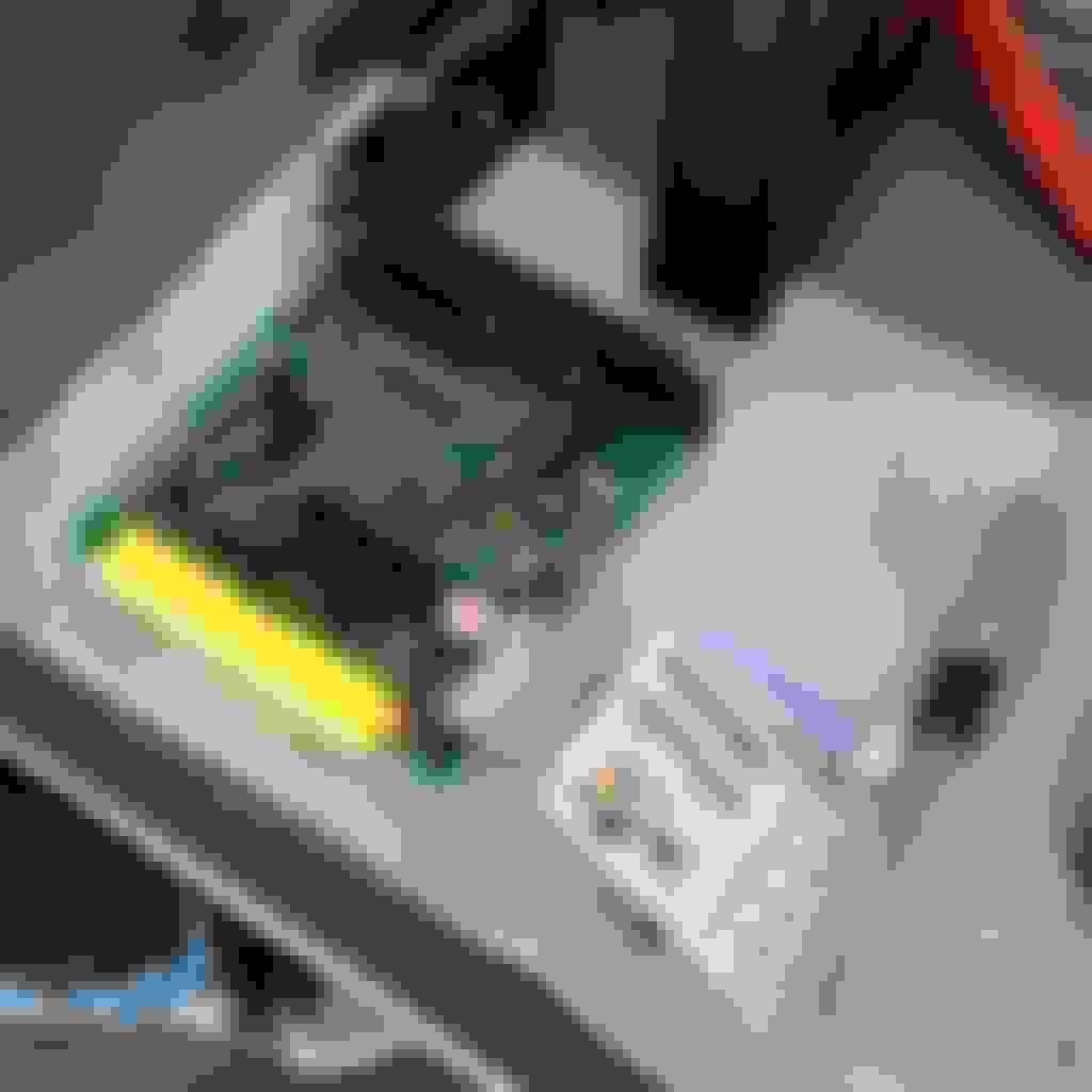
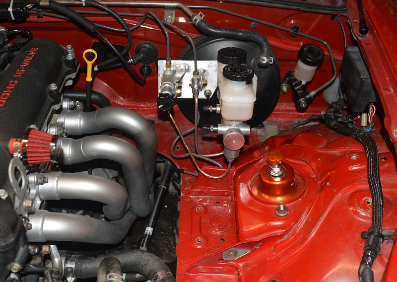
When I first installed my Wilwood master in conjunction with the big brakes, I did the same and ended up with "less than ideal" hardline routing. I experienced some problems with the fittings staying tight, which I believe was caused by the long, unsupported lines vibrating around under track use. I eventually re-did the lines, and built a bracket to hold the prop valve and T-fitting, and have had zero problems since.
The line to the left front is still not as clean as I would like, but I didn't want to fab a whole new line at the time.
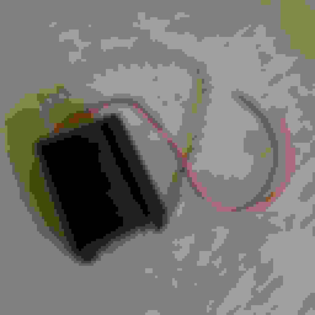
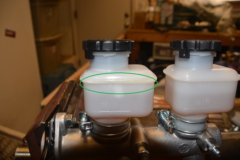
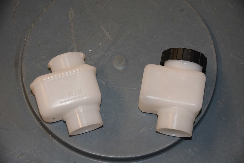
The other issue is the reservoirs on the Wilwood master. I had a mystery leak that drove me crazy for a while, and I finally realized it was the seam where the upper/lower halves of the reservoir were joined. One of my split, but it appeared it was only leaking under high G loading in left turns on the track. I replaced it with a newer style one piece reservoir, which solved the problem. I would have replaced both, but Wilwood was worthless (even their tech line) for part numbers, so I guessed and bought a reservoir from Summit that I figured would fit. It did, so I ordered another and it's waiting as a spare, or the next time I do a fluid flush I'll swap it out.
This pic shows where the reservoir split, and the second shows the two different reservoirs.
Watch out for a couple things on your brake setup...
Thank you Roda.
I really like the way you have your lines routed. I had noticed that some of the fittings were seeping slightly after the initial bleed. I will be sure to revisit the brake lines soon, as it is a safety concern.
May I ask where you found the copper hardlines, or are they custom? Fabricating some sort of bracket to support the lines has been on my to do list for quite awhile now, but always seems to get pushed back due to some other problem cropping up. I will also inspect the reservoir bottle for any signs of splitting at the seam. Do you happen to have the part number for the new style reservoir?
The included reservoir is a direct replacement for the reservoirs on the 1" master. I believe the part number for the reservoir included is 260-5752, but I have not been able to confirm that. I ordered the kit because the reservoir doesn't come with a cap, and I couldn't determine for sure which cap was correct, even after talking to Wilwood (yes, that was frustrating). I do know the two-piece reservoir uses a different cap.
I have very little knowledge and therefore experience when it comes to wiring, so I am bound to learn something.
I had purchased a MS Labs MS3 Basic many month prior to beginning the swap.
Along with the Megasquirt I also bought a CAN module to accept the digital signal from my wideband. Using the digital signal will greatly reduce signal noise.
Not pictured, AEM X-series wideband gauge.
Luckily for me, Andrew at TrackSpeed was willing to help me crack open the MS case and switch a few jumpers around on the board for various options.
Sequential fuel and variable TPS jumpers added.
Starting with a 1.6 chassis I needed to add a few more sensors along with the swap. Originally the NA6 chassis did not come with variable throttle position, and used a crank angle sensor driven off the exhaust camshaft. I needed to add a cam and crank sensor if I was to control VVT.
Not having any experience wiring anything automotive, I was unsure of the preferred way of connecting two wires. When working with smaller gauge wire in the past, I had always used soldering as a mean to create a solid connection. However it seems in the automotive world, with heat and vibration, crimping is the preferred method. I practiced a few times on spare wire prior to starting on the wiring harness.
To mitigate the amount of errors I could make when wiring , I dissected the engine harness from my NB for the cam and crank sensors, salvaging the greatest length of wire I could manage. I cut the wires for cam and crank from the CAS on the NA, and extended them to the front of the engine. I then split ground and power from the original sensor to each of the new sensors.
Here at the shop we mostly diagnose and repair FD's and have created a robust ignition system for them. My boss helped me construct an IGN-1A harness to adapt to my miata. I measured spark wire lengths and made a set of wires to route the coils in place of my washer bottle.
IGN-1A harness.
Definition of overkill for a 1.8 swapped Miata.
I now needed to find a location for my GM IAT sensor. I wanted to use the K&N intake tube from my NB but it did not have the provisions to mount the sensor.
I took a band saw to the pipe removing the bung securing the stock sensor and ordered a threaded bung from Vibrant. I found a shop nearby willing to TIG a 3/8 NPT bung to the thin aluminum tube.
Using AEM's X-series Wideband controllers required one additional step when compared to the Innovate. Digital signal comes from the blue wire on the gauge and I needed to connect it to serial port 2 on the DB9 connector on the CAN module.
DB9 serial connector.
Wiring the CAN module to the MS Labs supplied options plug. Only four wires needed, power ground and CAN Hi and Lo.
The next step will be the first start but only after quadruple checking my work.
Now to read up on Tuner Studio, and understand the basics of tuning. Will be much easier said then done.
The NA has been on the back burner ever since acquiring the NC but rest assured it is getting finished albeit at a much slower pace.
Every time I go out to work on the NC, I feel guilty. I can feel the NA staring at me gloomily, and I have given it some much needed attention in the past few weeks.
Since my last update, I have only changed a few things, most notably deleting the pop up headlights. The light output from stock is laughable, and went with a set of projectors. I picked up a set at MRLS last October for cheap. It was a bolt in affair with only a small notch in the front support needed. I then gutted the pop ups and all of the related motors, relays, and mechanisms. By doing so netted me a significant weight savings of around 16 lbs total if I remember correctly.
Little bit of clearancing to be done.
The added room in the engine bay is also a nice benefit. I purchased the Singular Motorsports headlight brackets to attach the pop up outer skins to the hood.
Projectors hiding behind gutted lenses.
On the ECU side of things I traced down my starting and wideband connectivity issues. After much reading and searching, I found many of my base inputs were incorrect and was able to get the car started. It was my eureka moment. I then wired in my tachometer, and it was ready to be tuned. Luckily a friend of mine has experience with tuning and he offered to help me set up a good starting point. We strapped the car on the dyno and completed a few base runs to confirm everything was working as planned.
I have since been driving the car around refining the drive ability of the tune. The ignition and fuel tables are great form the time spent on the dyno but everything anything below that will need some work. I know it is going to be a slow and steady process, and it will take time. However, I am learning the ins and outs of TunerStudio, and becoming more and more familiar with the car. It is a satisfying feeling when you can see the fruits of your labor and that the inputs you make, have direct and immediate result. I am also happy to report that I have since perfected the cold start and will catch first crank. Slow and steady wins the race.
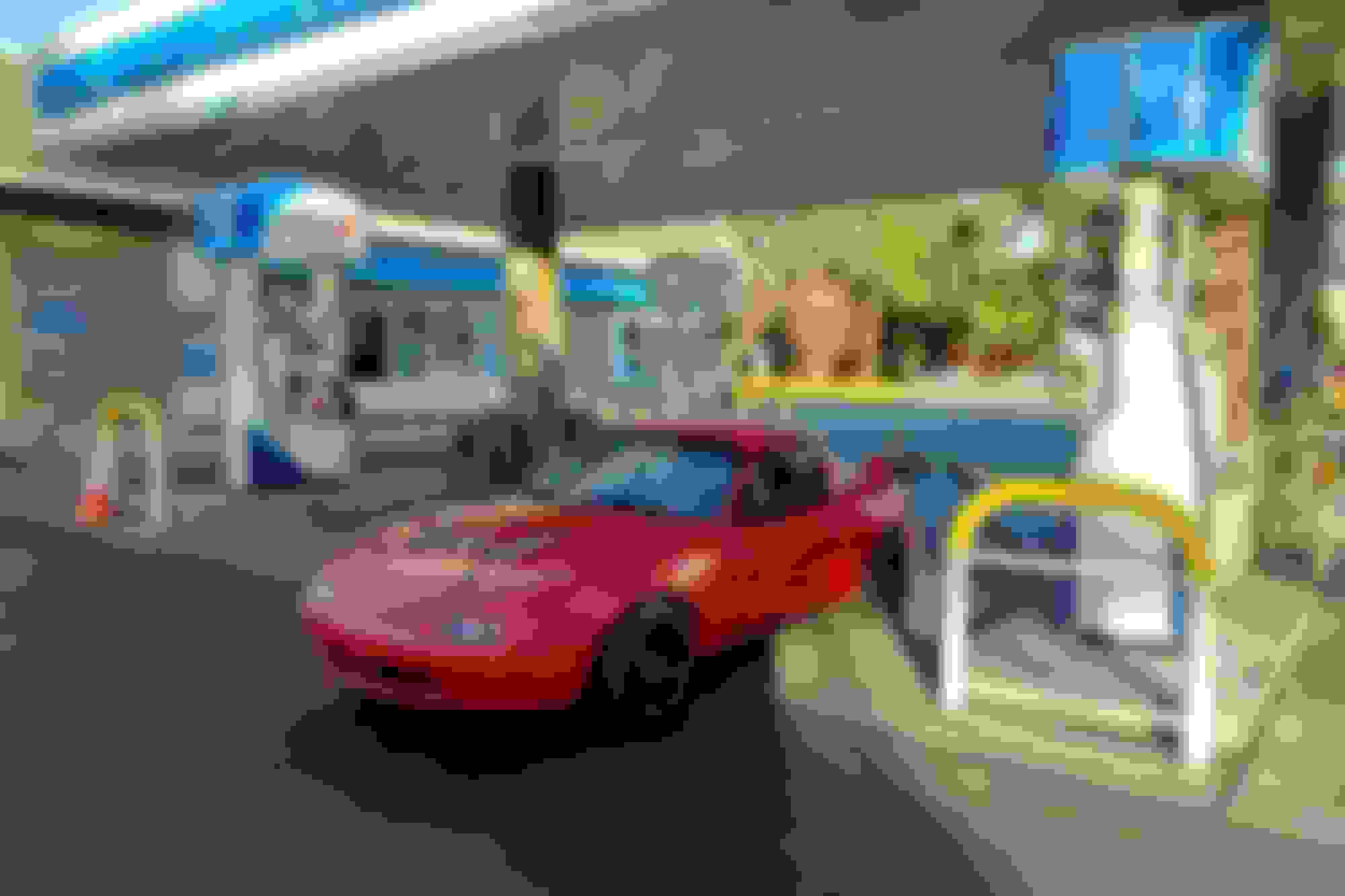
Filling up.
The next major thing I would like to address on the car is the seating position. I have removed the rear humps and have a custom bracket bolted to the floor but still would like to have more headroom. I have a long torso and short legs and due to the location of the seat my head will lightly brush against the top of the cage. This is a safety issue and I have since order a drop floor pan from Mazda Racers. I also want to retrofit the small splitter I made from my NB and finish up radiator ducting.
Other than that Rotten Tomato needs a few other odds and ends, heat tubing and sheathing for the remaining exposed wiring, mounting for radiator hoses but for the the most part is a running car.
After driving the car around the neighborhood a few times, one thing became immediately apparent my head was too close for comfort to the cage. There was not a chance that I could be able to drive the car without my helmet being in constant contact with the cage. It being an ergonomic problem was one thing, but most importantly it was a safety issue. I knew the cage was not moving, (or in hindsight was it?) so the only option was to drop myself lower. There have been quite a few threads discussing drop floors and it seemed if one was in order to fix the lack of clearance problem that presented itself. A click or two later, I had a drop floor on order. I chose the MazdaRacers drop floor pan, because I liked many of the options of the kit, 45* leading edge, and the included belt mounts to name a few.
What is included in the MazdaRacer kit.
I knew I wanted to have the pan professionally installed, and by someone who had done a drop floor or two, so I naturally gave TC a ring. Also peculating in the back of my mind were updates to the existing cage. Like an episode from Keeping up with the Jones, after seeing George's new cage, updating the current cage was on the back of my mind. I entertained and later justified the thought for increasing safety... right? A brief email exchange and phone call later, I had scheduled an appointment.
Packed and ready to hit the road.
I drove the car down, handed Tony the keys, and he told me to come back in two weeks.
I knew picking up the completed car would not be as simple as a task as dropping it off. For starters the windshield had been removed, the seat was not bolted to the floor, and oh yeah did I mention there was no front windshield? I must be getting wiser as I get older, because I did the sensible thing and rented a U-Haul trailer to tow the car back from Campbell. The same cannot be said for younger Bryan, he would have risked it driving the car home some 30 freeway miles to save a few bucks.
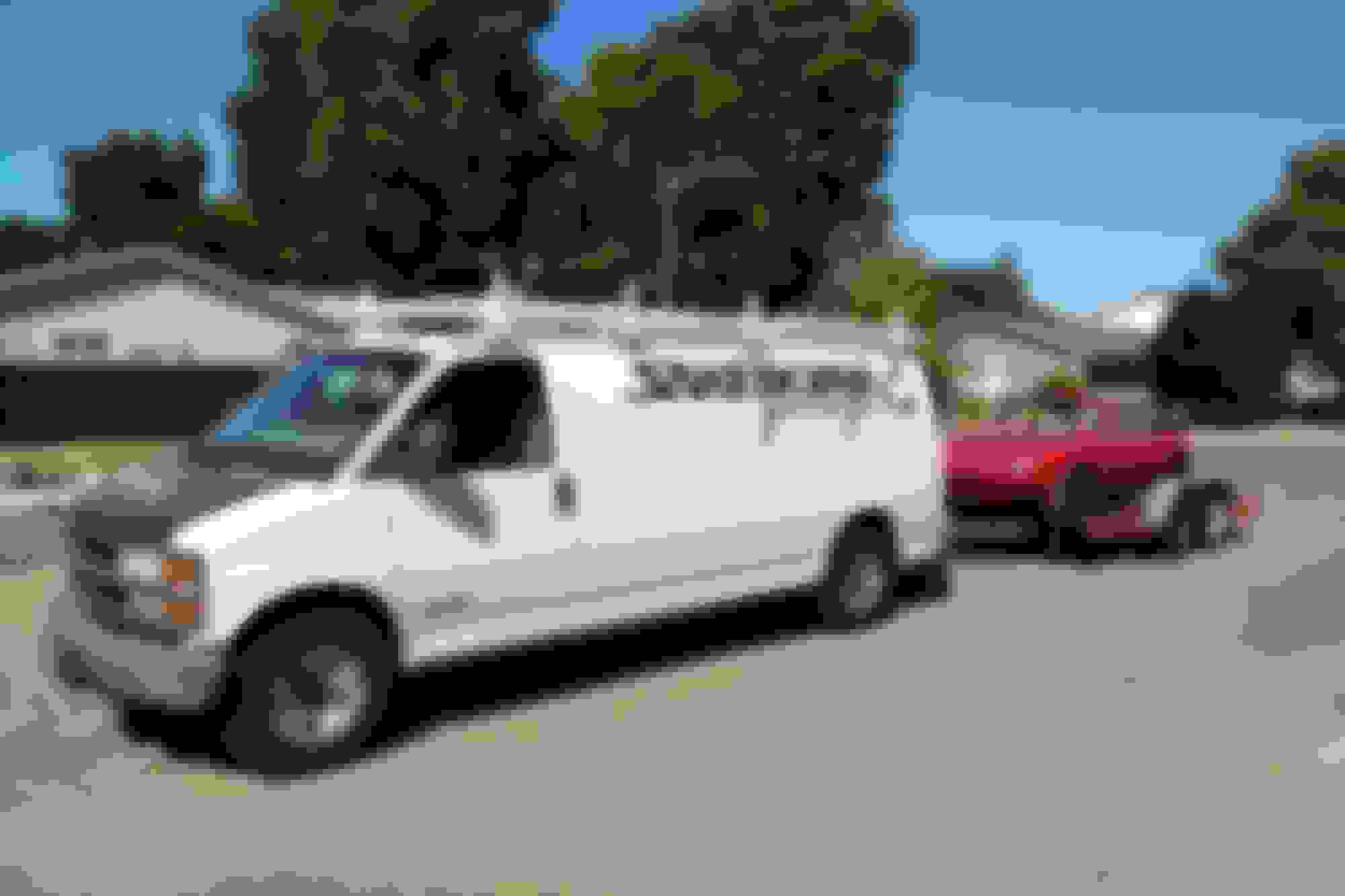
Thank you to the generosity of Heath, my boss, he let me borrow the company van to tow my monstrosity home.
This was the first time I had ever towed any sort of payload so I was nervous to say the least. The journey home was slow and measured, with many glances in the rear view mirror to see if the red hunk of junk was still there. To my surprise, my tie first attempt at tying the car down was tight and secure.
Safe and sound.
A few post back, I had stated that I would never again paint a cage. I must be a glutton for punishment, because I found myself here yet again.
Over the course of the next few weeks, I found time to spend a hour or two here working on the car. Eventually the bare cage turned more and more white. I had used the few tricks I had learned from the first time, to make the process a bit less painful, but it was still a bear.
Mid paint session.
The jungle gym.
Finished.
The updates to the cage have also dramatically increased chassis rigidity. Gone was the Spec Miata cage, and in its place was a 12 point cage. I was glad to have gone ahead with additional cage upgrades, and I knew if I hadn't I would have kicked myself for not doing so. The new cage included a straight dash bar, attachment points at the A-pillar, rocker panel, and B-pillar. Various gussets were added throughout to further increase rigidity. Suffice to say, I was thoroughly impressed.
After finishing painting the cage, and drop floor I was able to fit the seat. I can attest that the drop floor makes a world of difference. Not only does my helmeted head now clear the bar with inches to spare, it places me in the perfect seating position in the NA. The earlier cars it is tremendously difficult to find a comfortable seating position, but with the drop floor it feels like an entirely new car.
I have never felt as if I have had as much room in a NA/NB and am now a firm believer.
Safety inspector assessing the integrity of the welds. It passed.
The updates to the cage have also dramatically increased chassis rigidity. Gone was the basic Spec Miata cage, and in its place was a 12 point cage. The new cage included a straight dash bar, attachment points at the A-pillar, rocker panel, and B-pillar. Various gussets were also added throughout to further increase rigidity. Suffice to say, I was thoroughly impressed.
The main motivation to finish this project is to be able to give the car to my dad once it is completed. I am excited to be able to share my love for the track with him, and with us both being able to drive in a weekend will be a dream come true.
My father grinning ear to ear, testing the new modifications.
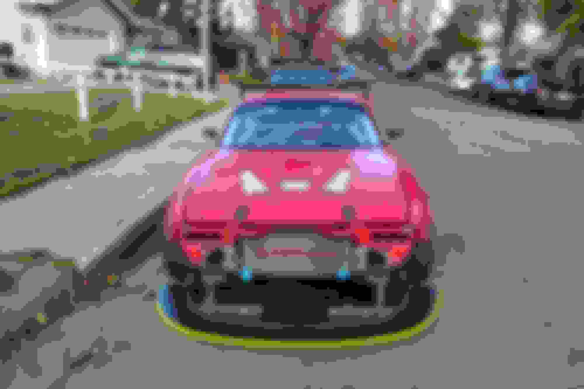
Wanting to replicate the tried-and-true air dam and splitter combo here is my attempt at it.
The effectiveness at reducing front drag and lift, while being very difficult to mess up, was something I have been wanting to do for years. Studying others iterations of a front air dam, and I wanted to incorporate the best features, and to make my air dam and splitter detach within a matter of minutes. I imagined using quick release pins, and quarter turn fasteners wherever possible, all while not sacrificing strength. The plan was to have air dam riveted to the front bumper and the splitter to mount to the frame rails. The final mounting solution differed slightly from the original plan.
Purchased 0.110’’ HPDE 10ft Roll for the Airdam, KazeSpec Race mounts, 4’x8’ �”” Birch Sheet from the local Home Depot, front bash bar from Zerek Fabrication and various hardware from McMaster.
First mock-up, marking the holes for the splitter mounts, trimmed the birch sheet for mobility.
The KazeSpec Engineering includes four brackets that utilize the threaded holes in the front of the frame rails. Two quick release pins then capture the square tube for the splitter mount. They are sturdy, and can be removed from the car in a matter of seconds, exactly what I was looking for.
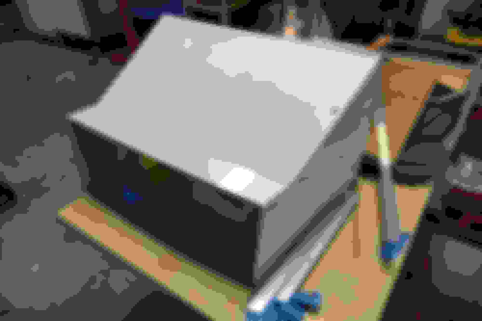
This being my third or fourth splitter, I had a template, and cutting the birch to its final shape was a quick and easy affair.
Cut to shape.
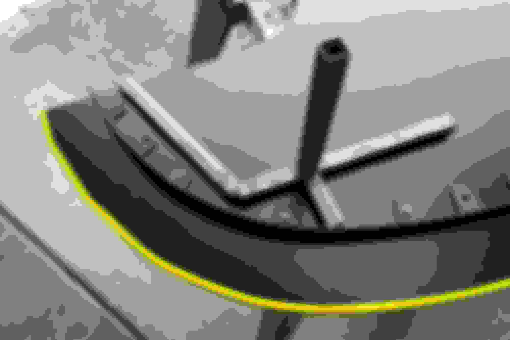
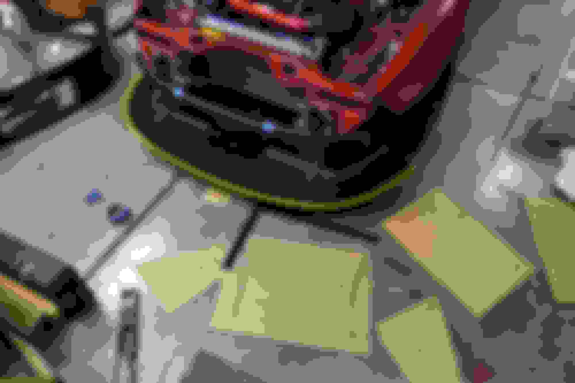
I then painted the splitter flat black and as an added flair, I painted the leading edge, fluorescent yellow. Finally I added another coat of spar urethane to protect the wood against water and oils.
Painted.
Now I had the task of mounting the plastic roll to the front bumper. I found that Dzus quarter turn fasteners might be the solution I was looking for. After purchasing a few springs and fasteners I found the perfect combination to sandwich the plastic sheet and the front bumper.
Template out of cardboard, and marking the HDPE roll for its first cut.
Installing the fasteners consisted of marking, drilling, fastening, punching out the inside of the rivet, hammering, and more riveting. After the first few fasteners it went quickly. I only used as many Dzus fasteners to have the HDPE match the contour of the front bumper.
After installing all the Dzus related hardware, I then had an idea line where I could cut the bottom portion of my bumper.
Out came the saw.
Splitter brackets installed, and mounted on the car, I found the outboard edges of the splitter deflected more than I liked. Naturally this is probably overkill, but I wanted to come up with a solution. I purchase some identical square tubing and cut it to shape, to extend the mount to the outer edge of the splitter. I also purchased M8 weld nuts to secure the splitter to the new material added to mounts.
Corner extension cut and welded.
Ducting is an important part of the cooling system for any car that goes on track, and I thought it would be best practice to keep that in mind in the future. This meant that I needed to cut out the front crash structure between the frame rails.
Scary yet necessary step. Cardboard placed in front of the radiator to prevent any unwanted flying pieces of metal from visiting the delicate fins and tubes of the radiator while cutting.
I wanted to add back in some torsional stiffness, bridging the gap of the void from my new radiator opening. The front bash bar from Zerek Fabrication would do the trick. Although there was a slight problem the splitter mount and the bash bar both occupy the same space and share the same mounting location.
After a bit of thinking, I traced the rear of the bash bar plates, and extended the 3/16’’ steel plate to adapt the splitter mounts to the bash bar plate.
Template.
Left and right plates cut and marked.
The 3/16'' steel plate was difficult to cut with the angle grinder. I filed down the radius of the plate to match that of the bash bar to ensure the strength of the future weld.
Safety first.
More welding required.
With the plates welded I then need to fasten the splitter brackets to the bar. I drilled two holes in each side of the new plates and then tapped the holes for a M6 socket head bold. This will then allow the old mounts to be used and in theory should I have an off-track excursion and the splitter make contact with something solid, it will shear the M6 bolts and save the chassis from the majority of the forces.
Tapping.
I had to drill holes in the sheet metal around the frame rails to make clearance for the head of the bolts. I can still remove the socket head bolts with the splitter attached to the car.
The studs poking through with the head on the backside. The slots in the splitter bracket allow for some deflection should the splitter see an impact, and in the worse case scenario the bolt should shear. I do have cable attaching the splitter to the bash bar should the bolt shear to prevent the splitter from making its way under my front wheels.
I also had to remove a few inches worth of square tubing from the splitter mount to keep from contacting the horizontal section of the bash bar. This also resulted in needing to drill two new holes in each section of the splitter mount to allow the quick release pins to pass through.
All in all, the front end was a lot of work and took me many hours with many revisions partway through the project. However, I am happy with the end result and I can dismantle the entire front end, splitter, air dam, and bumper with nothing more than a flathead screw driver, a 10mm socket, and about 5 minutes’ worth of effort.
Splitter mounted to the front bash bar waiting to go on the car.
Clarification - the lower edge of the air dam just sits against the strip secured to the splitter? Seems like that should work, given the curve of the air dam stiffens it, but I guess I am a belt and braces DIYer ...
Thanks, looking back all of the hours did add up in the end, but I am happy with the end result. I do want to revisit the splitter mounts to triangulate the legs and then spray on a coat of paint in the near future.
Originally Posted by Gee Emm
Nice work!
Clarification - the lower edge of the air dam just sits against the strip secured to the splitter? Seems like that should work, given the curve of the air dam stiffens it, but I guess I am a belt and braces DIYer ...
You are correct, the strip is Vigoro garden edge trim, and protrudes about an 1 and 1/2'' from the top of the splitter.
It has tabs with holes drilled every 4'' and is made from a durable plastic that is also flexible.
I have not tested the car on track yet, and have only tested at highway speeds. I have not noticed any buckling or deformation of the HDPE nor weird stress on the fastener mounting locations.
I will report back after its maiden track test, but I predict it will be able to withstand all the abuse I can throw at it.
With the air dam and splitter done, I could move on to the next task at hand the radiator ducting. This is an integral part of the cooling system, guiding the air through the radiator keeping the car cool. I now had the constraints of the splitter and the bash bar to content with, but with the added benefit of removing the OEM crash beam. The goal of this project was to make duct that sealed to both the air dam and the radiator, while still being easily removable with simple hand tools.
While not the cheapest, I ordered a 4'x8' sheet of 0.063'' Aluminum from OnlineMetals.com. Shipping was quick and painless and did not have to worry about the added hassle of moving such a large sheet of material. Out came the measuring tape, and plenty of cardboard.
CAD (Cardboard Aided Design)
The original plan was to have a gentle radius duct leading to the radiator. The simple hand tools I had in my garage all but ruled out that option.
After a few hours I had a general shape which I was happy with.
Another thing I had come to realize was that the material was too thick to bend in the small metal brake I had access to, so bending the edges to meet was not going to be possible. Instead, I went with an aluminum angle and rivet approach, which in hindsight will be much easier to service/replace any damaged panels in the future. I purchased a few sticks of 3ft 1/4'' 5052 aluminum angle from Home Depot.
Transferring to aluminum sheet.
Aluminum angle sitting alongside going to be used to secure the box together.
Slowly coming together.
I purchased 2.5'' NACA ducts from Pegasus racing to mount on the inner walls of the duct.
Slow and tedious task of drilling all of the necessary holes for the 3/16'' rivets and provisions to mount the NACA ducts.
The Dremel tool was my best friend during this step.
How well the duct seals to the radiator.
High temperature closed cell foam was used between the aluminum angle and the end tanks to provide the best air tight seal I could manage.
Also to not wear a hole through the end tanks from vibrations over time.
I went for an ostentatious yellow vinyl to wrap the inside of the duct. It took me two tries to match the leading edge of the splitter, but I think it came out well. I may wrap it black in the future for a more discrete appearance, but I guess the whole car is loud, therefore I am still undecided.
Many 3/16'' rivets.
I mounted the duct to the car in four threaded OEM locations with M6 bolts. The inner edge of the aluminum angle slides behind where the AC condenser typically sits and provides tension for the duct to sit flush with the radiator end tanks. In the photo above you can see the two rear brackets directly behind the NACA ducts.
Aluminum angle missing the closed cell foam sealing it to the back of the air dam,
The photo below illustrates my implementation of the NACA ducts on the inside walls of the duct to feed cool air to the brakes. I am not sure if I properly integrated the duct into the design, as NACA ducts generally are positioned in low pressure areas of the car, pulling in the fast moving air to feed the duct, while minimizing drag. Where these are placed inside the duct, in front of the radiator that should be a high pressure zone, so I have my doubts on the effectiveness of my design.
Only testing will tell.
The only benefit I could discern was the angle at which the ducts allowed me to route the brake hose. It allows for a straight shot to the backing plates making hose routing a breeze.
Aluminum tape was used to seal any of the small gaps left between the panels. The clearance between the bash bar and the duct is miniscule.
Even with the four mounting locations the duct is solidly mounted to the car, and I see no foreseeable issues in the mounting department. Missing in this picture is the foam sealing the upper portion of the radiator to the duct.
Finished.
This projects took many more hours than I had anticipated.
On the bright sided I now have all the dimensions and tools, so if I damage it in the future, the next versions should take a fraction of the time.
 01-12-2019, 04:58 PM


 1
1