When you click on links to various merchants on this site and make a purchase, this can result in this site earning a commission. Affiliate programs and affiliations include, but are not limited to, the eBay Partner Network.
I fear I am a glutton for punishment, or just really want to tinker with the car rather than drive it. Anyhow, I decided now was a great time to rip the entire harness out of the chassis and prune it down to the bare essentials. I justified this to myself, with the idea of less possible failure points, simplified routing, and less of a rats nest behind the dash.
Hours upon hours of studying the 1991 Factory Wiring diagram, cutting and trimming out everything that would not be needed moving forward in a track car. Not wanting to work within the cramped confines of the car I elected to separate the car and the harness and subsequently brought it inside to work on it in the comfort of my home.
Little did I know the nature of the task that was ahead of me.
What I found to be the most tedious part was the unwrapping of the old harness, the electrical tape was aplenty, brittle and cracking with age. Thankfully the majority of the harness was untouched, and the previous owner only had installed an aftermarket radio.
Progress was slow.
Slowly pruning the harness of unnecessary wires.
With my car being a non-CA NA6 it was wired with batch fuel from the factory. All that would be needed to switch over to sequential would be opening up the MS3 and switching two jumpers and running two new trigger wires to injectors three and four.
The jumpers needing to be reconfigured were JP10 and JP11 near the bottom of the board. The two new wires would be configured to 2Y and 2Z on the existing ECU connector.
I then needed to source the factory ECU pins to pin the two new trigger wires to the original connector. The plastic housing and pins were sourced from Ballenger. The connector was a clamshell, and had two tabs on either side in order to de-pin the connector. With the plastic coming up on 24 years old, I ordered a spare housing to be on the safe side.
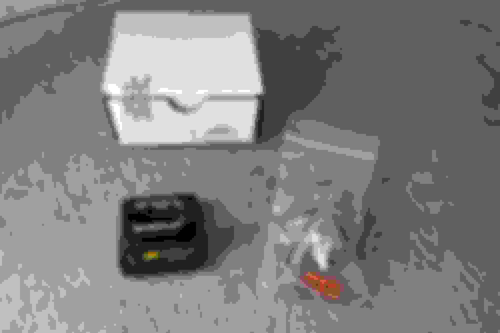
The kit came with a housing and spare contacts and showed up in a matter of days.
Ballenger CONN-75909
Old harness and being converted to sequential fuel. Labeling the injectors so I could reinstall them incorrectly. The injector harness was then wrapped in electrical tape.
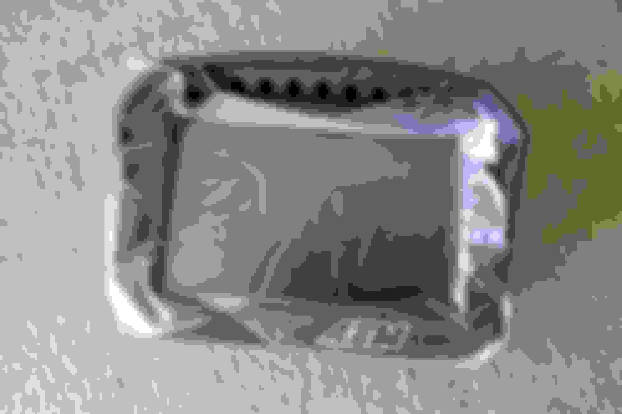
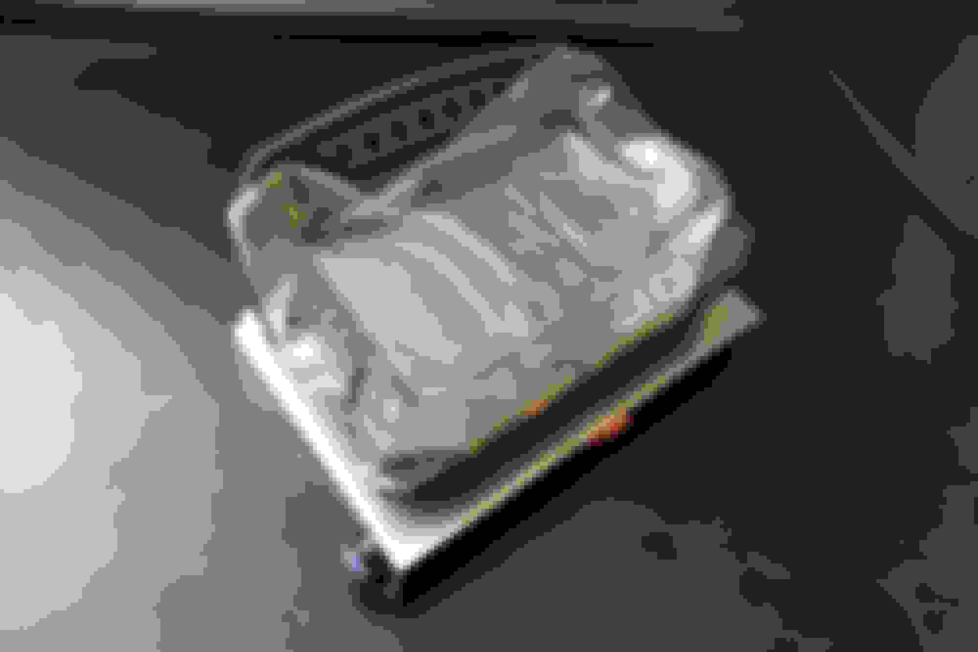
Changing the jumpers inside the MS3 Basic.
It is always fun opening up the brain of the car.
It could be a placebo, but I feel after switching the car over to sequential fuel, the car idled smoother and would be more responsive to throttle inputs. Fuel economy was another benefit, but was not at all practical, considering this is a track focused car.
Harness on its way back in the car.
To finish up the harness I wrapped the entire harness in split braided loom sheathing from Pegasus Racing. I ordered various sizes from 1/8'' to 3/4'' to wrap each part of the harness the best I could. 3M Super 88 was used at connecting points of the braided loom as well as securing the ends of the loom to the harness. The sleeve was high quality, both providing good abrasion resistance as well as good flexibility with the added bonus of being able to unwrap the harness should I want to make repairs without needing to destroy the entire sheathing.
Self-Wrapping Split Braided Sleeve from Pegasus
After many hours spent, I can safely say that this project was not worth the time invested, but on the bright side I can now identify each connector on a stock NA6 harness. Cutting out all of the unnecessary accessories, yet still retaining turn signals and headlights, I weighed the bad of discarded wire and it came out to 8lbs. I secured the harness to the car using adel clamps.
This project was very much a project of personal pride, and knowing that underneath the dash was a tidy and neat harness. I also feel I have a better understanding of the electrical system of the car and should be able to diagnose problems more easily in the future, so that is at least worth something.
With the boring wiring now behind me, I could focus on the more interesting parts.
I removed the gauge cluster and all associated wiring when trimming the harness the first go around. In order to track important vitals of the car a digital dash was in store. After being exposed to a Racepak a few years ago I wanted something similar for this car, without all of the software hurdles.
AEM CD5-LG 30-5603
Brief rundown of the dash.
Internal GPS
200MB Onboard Logger
CANbus
Custom Configurable Pages
Configurable Warnings/Alarms
This dash seemed to be the perfect fit for the car. It is their 5" display with all the bells and whistles. Included with the dash was a GPS module, harness, and a USB cable.
Also purchases was AEMs 6 Channel CAN Bus Module. I originally purchases this to add fuel level as it had a dedicated 0-250ohm fuel level input. All that was needed was to measure the resistance of the variable resistor in the stock miata fuel tank, and calibrate the fuel level channel to match that of the car. The range for my car was 3.1-109.4ohms well within range of the Module.
I am now going to add oil temperature, and oil pressure on the spare inputs as well as a few other sensors to be determined.
6 Channel CAN Sensor Module 30-2226
AEM Electronics had detailed instructions listed on their website to get the dash up and running. To my surprise they even had Megasquirt specific instructions and related .dbc files which made setup even easier.
The dash has two buses allowing me to add addition sensors not on the same bus as the Megasquirt. The Megasquirt would be configured on Port 2, and all that would be needed to connect CAN Hi and CAN Low to the ECU and I would have access to all of the information coming from the ECU.
To power the dash, a switched 12V power source and a ground was needed.
Up next was a way to mount the dash. I re-purposed the mounts from my LongAcre review mirror kit to clamp onto the straight dash bar. The slotted holes would allow adjustment forward and aft, while the mount could be clocked around the bar to the perfect position.
Two mounts behind the steering column, please excuse the mess of wire throughout the car.
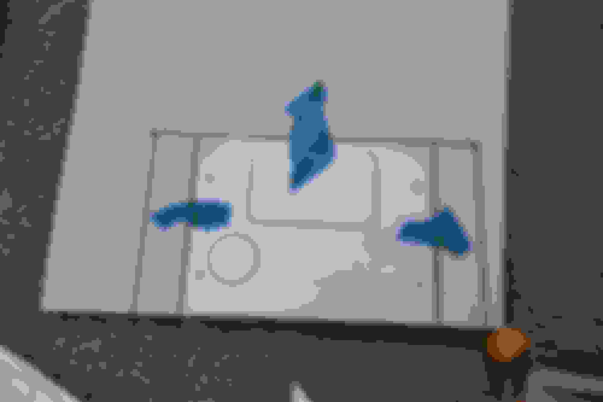
The dash itself had four 8-32 mounting studs with rubber isolators. AEM was kind enough to include a template in its instructions.
I drew up a quick template and got to fabricating.
I made a bracket out of aluminum and bent the wings in to add some rigidity, as well as a place to mount to the mirror brackets.
Hand tools for the win.
Before reinstalling the wiring harness back in the car, I wanted to make sure everything was in working order, which meant laying the wiring harness over the windshield of the car. It was quite the spectacle.
Success, it fired on the first try.
It is alive!
Included in the harness were two flying leads for a lap beacon and dimmer. The onboard GPS could mark a start/stop for lap timing and required a momentary switch to ground. I purchased a Otto P9 dome momentary switch from Mouser Electronics.
Purple, because being a fan of F1, denotes the fastest lap. I thought it was a fitting touch.
Dash mounted in its final resting place.
The mounts allowed to dash to placed in the ideal place behind the steering wheel allowing full view of the screen.
The CD5 come preconfigured with layouts that can be customized in their entirety.
Very racecar.
The pages of the CD5 are fully customizable and I foresee many hours being spent customizing the various screens to my liking. It took me a few hours to learn the ins and outs of the software and I tried replicating the layout of a Lamborghini Huracan GT3 EVO.
I have not yet figured out how to display the calculated gear, but that is something I will be tinkering with in the near future.
A feature that I find incredibly useful is the simulator tab which allows you to test the changes you make to your design, to see how it will function in the real world.
Dash Design 2 Software.
The CD5 is incredibly powerful, intuitive to use and well worth the cost. It is infinitively customizable, and the warnings and alarms are a nice benefit that can easily alert me if something goes awry.
To get the car road worthy I was in need of a headlight solution.
I removed the original pop-ups quite some time ago now and decided to deal with that problem at a later date. Well, with the car receiving its finishing touches, that time was fast approaching. After reading through Aiden's Projector In Turn Signals: A Shitty DIY Guide, I wanted to do something similar.
Aiden's guide was used as inspiration, but I thought I could do it a bit cleaner. Instead of mounting the projector to the backside of the bumper support, I wanted to nest the housing inside the sheet metal. This turned out to be slightly more complex but would yield a better end result.
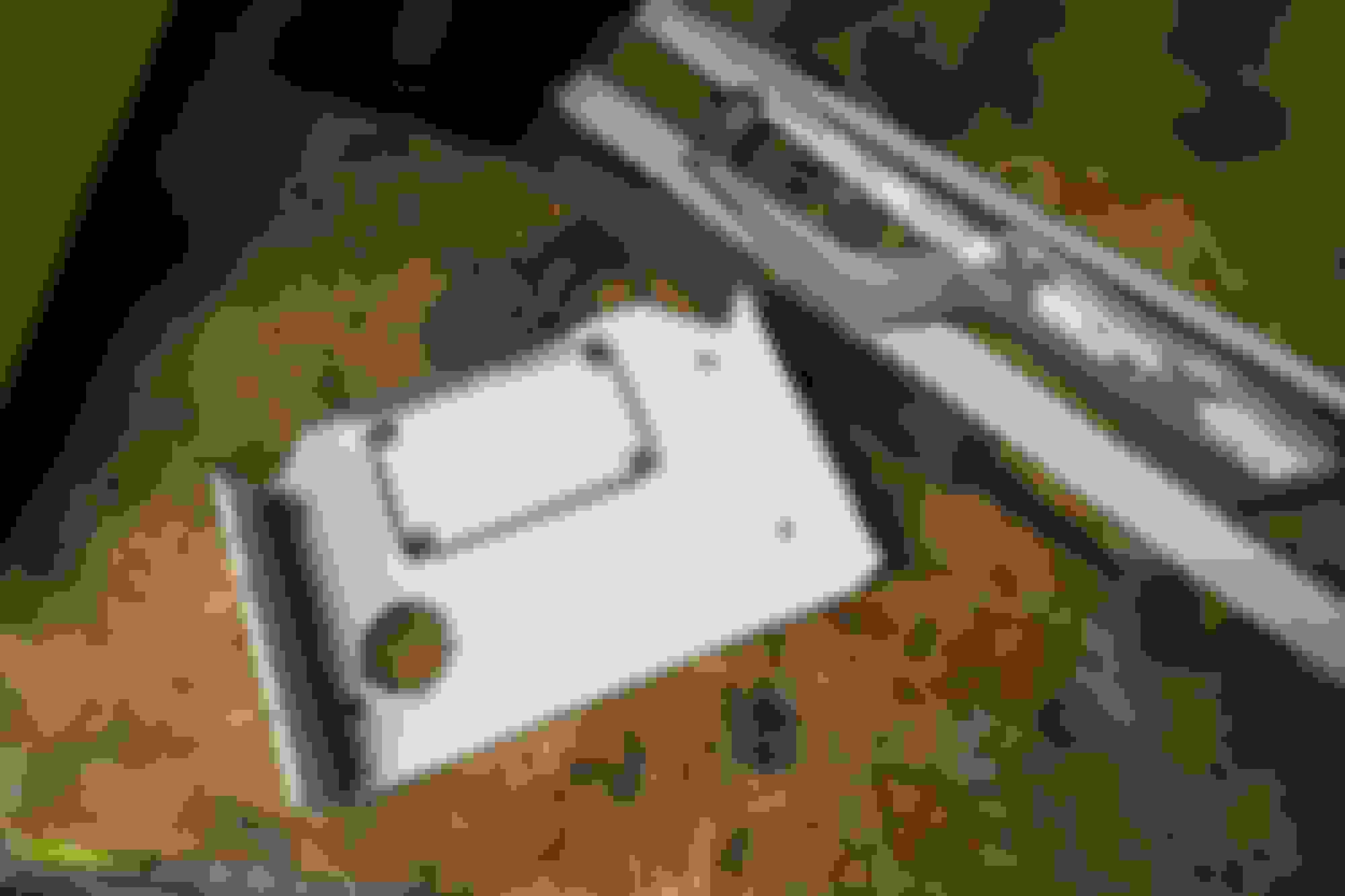
Two Hella 60mm projector housing were ordered along with HB3 LED bulbs from Amazon.
Marking and measuring the housings centerline.
The first hurdle is that the opening in the bumper support is not a flat plane. The lower sheet metal is flat, but the top portion will require some work.
Rough outline of the bottom radius to be cut.
Out came the angle grinder, quickly becoming one of my most used tools, to cut a relief in the back of the support. I could then test fit the projector in its proposed mounting location. Nothing fancy needed here, just a rectangular cut to clear the two upper tabs on the projector housing.
Chop chop.
After the first round of cutting, this is what I was left with.
The housing was in, but far from finished.
The sheet metal was doubled up on the top of the support and took a deal of cutting, filing, and massaging to get the housing to sit flush with the front part of the support.
That is more like it.
The bottom portion required use of a carbide Dremel bit to shape the metal into a somewhat smooth radius. It was a slow process, that no one will ever see, but it was a project of personal pride.
Isometric view.
This photo is out of order and the outside marked rectangle was cut to clear the two tabs on the housing.
So much more room for activities. I feel it is a much cleaner install as well.
Top view.
I gave the newly cut holes a splash of red paint to prevent rust, even though being in sunny California it is not much of an issue.
All that was left were the four holes needed for the adjuster screws to aim the projectors. A quick meeting with the appropriately sized drill bit and it was done.
Final hole size.
Easy access to the adjuster screws.
The clearance between the projector and the hole was tight.
Now all that was left was to repeat the same process on the other side.
All done.
I had a pair of turn signal housings that were already apart and bolted them onto the bumper skin.
However, the inner ricer in me also realized that the turn signal intakes lined up perfectly with the projectors and had provisions for the turn signal bulbs.
So on they went.
This is another project where the simplicity of the finished product belies the complexity involved. It turned out far better than I had hoped, and the light output far exceeds that of the stock pop ups.
A few maintenance items left to check off. Fuel pump, filter, and new radiator fan were on order.
On the NA6, the fuel pump kit is a plug and play, without even the need to splice into the stock hanger wiring. The 29 year old fuel hanger looked surprisingly good and no signs of rust in the tank.
With the assembly out of the car, now would be the prime opportunity to add in my fuel level gauge to the AEM dash. The OEM fuel level sender is a variable resistor and all that is needed was to measure the resistance values of the arm at "full" and "empty".
I recorded a value of 3.1 ohms full, and 109.4 ohms empty. This was perfect as it fell in between the 0-250 ohm range of the CAN module I was going to use. A quick custom linear channel added into the dash software later and we were in business.
Thankfully the fuel hanger assembly cleared the cage and was a painless process.
Peering down into the bellows of the tank.
When replacing the fuel pump I have heard of a few problems arising when using the fuel sock from the Deatschwerks kit. The sock is not the same quality and is shorter than the OEM unit. To avoid any issue in the future a new OEM sock was used.
DW200 and new fuel sock going on.
The fuel filter was next on the list, and it was doubtful that it was changed in the last decade.
Crusty.
Immediately after completing the wiring job on my car, I found that the car was overheating while at idle. The radiator fan was not kicking on, and coolant temps were on the high side.
Luckily I caught it in time and investigated the problem a bit further. The initial thought was that I had somehow cut out the wrong wire by mistake taking out my fan, being it was the last thing that I had touched. Usually the last thing you touch will be the first cause of your problems. I searched and searched and found no faults, and after triple checking everything, could find nothing wrong. In a last ditch effort I measure the fan, and it was the fan that finally gave up the ghost, coincidentally at the exact time that I finished the wiring.
Phew at least I found the culprit.
One Spal fan later, and a few quick aluminum brackets later. I covered the outside edge of the fan with rubber trim to protect the fragile fins and tubes of the radiator.
SPAL VA10-AP10/C-61 12"C/12V
And now onto the slightly less boring things.
With the majority of the car together, I guess it is time for an initial shakedown.
Not wanting to go too far away from home, and not stress any component on track on its first outing, I settled on a local autocross with Golden Gate Lotus Club.
The drive to Cow's Palace was fun, with many stares directed my way along the 30 minute trip. When I actually arrived at the front gate, the glances only continued. I was dubbed the "aero miata" and my car looked slightly out of place at the event. However everyone I did come across was quite fond of the car and poked around it in the paddock.
Parked in the shade of Cow Palace.
No powersteering combined with the relatively low speeds of autocross made the car a bear to drive. My arms were getting a workout. This being its shakedown, I was not worried about times during the event. Even though I registered for the Fun group, I was still slightly curious, and to my surprise, found that I was more towards the pointy end of the group. I would call that a success.
Before taking the car on its maiden track outing, I wanted to add one last piece of insurance.
I have read about all of the headache that comes along with the Skunk2 throttle body, but I figured it was the lesser of the two evils when compared to ingesting a screw. This car will live the majority of its life at, or near redline, so I was not viewing it as an upgrade, instead only for reliability.
As documented before, the actual hardware received will vary, and I was lucky enough to receive the correct gaskets and IACV plate.
However some of the included hardware was the incorrect length, although nothing a quick trip to the local hardware store can't fix. The Skunk2 would receive the standard known treatment before ever touching the car, including drilling new holes for the return spring, and a healthy dose of Loctite for everything that did not need adjustment.
Upper intake manifold coming off to reveal a generous coating of oil.
The stock intake manifold is 59mm and the new throttle body is 64mm so the intake manifold would also be port matched to reduce any unnecessary steps in the intakes flow path.
Here you can see the small lip of material that needs to be removed for a smooth transition between the throttle body and the intake manifold.
I opted to remove the upper manifold from the car to be sure absolutely no aluminum shaving entered the engine. A carbide bit made for quick work of the aluminum opening.
Patient under the knife ready for surgery.
Results of my shaky handiwork.
Next was to flush out all of the shavings from the upper manifold. The manifold had 100,000 miles worths of road grime, so it was already in need of a thorough cleaning.
After much scrubbing I was left with something more presentable. I was sure to clean out all of the aluminum shavings from all of the nooks and crannies before reinstalling it back on the car.
On to the throttle body itself.
The spring tension that is shipped with the Skunk2 on the throttle plate is abysmal, not allowing the throttle plate to fully close, causing a high idle. Hoping to avoid this, I drilled a new hold to create more preload on the spring.
The new drilled hole is the right-most hole in the picture. Location of the new hole was approximately 3mm away from the existing hole.
Swapping over the TPS, and IAC over to the Skunk2. The two phillps-heads holding on the IAC were quite stubborn, and an impact driver was used to prevent stripping out the heads.
I blue loctited all of the bolts, setscrews, besides the red idle screw on the top of the throttle body.
The hardware provided from Skunk was incorrect, and one of the M6 button heads that was to go in the blind hole attaching the IAC plate to the throttle body would bottom out before the plate would sit flush with the throttle body.
The M6 provided was 12mm long, but needed to be 10mm to not cause interference.
Bolt bottomed out in the blind hole.
The stock throttle body routes coolant through the assembly to aid in freezing climates. The Skunk2 has no such provisions, so a solution was needed. Most other loop the two coolant lines coming from the oil warmer to the water neck with a straight fitting. I did not want to do this because it was more potential leak/failure points and I did not have a way to secure the hoses.
Luckily, afm had posted a few months back that Pegasus had released double ply coolant caps that would be ideal for this very situation.
Factory 1.8L oil warmer, located just under the intake manifold.
The two coolant hoses put up a mighty fight, but in the end I prevailed. The hoses were 21 years old at this point, and the slightest bending caused them to develop a leak.
Here you can see the two hose clamps adjoining the two hoses, before I had capped the lines.
5/16 Coolant bypass cap from Pegasus.
Skunk2 assembled and ready to go back on the car.
Even though I had loctited everything, I paint penned all the fasteners so that I could monitor any bolt that decided it wants to back out.
With the throttle body on the car, I then adjusted the throttle stop on the throttle pedal to bottom out before the throttle cable to prevent any undue stress on cable, or throttle shaft.
Hopefully the knowledge of everyone who has struggled before me will allow a hassle-free experience with the throttle body, but somehow I think that will not be the case.
Hopefully the knowledge of everyone who has struggled before me will allow a hassle-free experience with the throttle body, but somehow I think that will not be the case.
That's what I was hoping when I put the S2 throttle body on mine as well, but alas. I had loctited all of the bolts that actually attach things to other things, but I had missed the one that's actually just there as a stop for the throttle return. After a couple thousand miles it loosened up and started backing out, with the initial symptom I noticed being that I wasn't getting as much engine braking as I expected on the freeway. By the time I got off and to my destination it was idling at like 2500 RPM.
Anyway, just a heads up that there's another screw hiding behind there that you may not have seen.
Anyway, just a heads up that there's another screw hiding behind there that you may not have seen.
--Ian
Thanks for the heads up Ian. I have now put thread locker on all the things.
Buttonwillow Black Friday 2021
Every year I would do my best to make the trek out to Buttonwillow to participate in SpeedSF's Black Friday event. With the NA finally done, I was ready to get it out to the track.
What better way to test the car than a 460 mile round trip to the track?
Packed to the brim with might possibly be every tool I own. No tow vehicle here.
One of the first issues that I ran into was around dusk. I underestimated the brightness of the digital dash, and it proceeded to blind me about an hour into the trip. I quickly pulled off and connected my laptop and adjusted the brightness manually. Note to self, set up the dimmer feature when I get home.
The car made it to Buttonwillow without any further issue, and aside from the slightly burning retinas, dare I say it was quite comfortable. Between the removable windows, seat cushion, and blue tooth headphones, I felt quite refreshed after the 4 hour drive.
First session of the day was another shakedown and confirm nothing would relieve itself from the car at track speeds. This uncovered the next issue. I noticed during a few times throughout the lap, that my downshifting was atrocious. In the moment, I attributed it being rusty, and thought I had forgotten how to heel-toe.
Only after pulling into the pits, that I noticed that my throttle was sticking open and would idle somewhere in the neighborhood of 4,000-4,400 rpm.
Yikes, not good.
Between sessions tear-down.
Initially I thought it was the spring preload not being strong enough to fully close the throttle plate. I adjusted the preload via changing which hole located the spring thinking it would be a quick fix. I drove a lap around the paddock, and the throttle continued to stick open.
After all the testing on the street, and autocross, this issue never presented itself. I guess it is true when they say track hours are magnitudes greater abuse than any street car will see. As soon as the throttle saw heat, it would begin to seize open and you had to forcibly close the throttle to get it to close.
Fortunately, my friend David was at the track, and has also had his fair share of problems with the Skunk2. I popped over to his trailer and he loaned me one of his Ebay knock-off throttle bodies to swap on to the car. He has good luck with them, and prefers them compared to the genuine Skunk part. This allowed me to drive the remainder of the day, and more importantly, make the drive home.
Nothing to see here, just swapping broken parts.
I brought extra thread locker with me for this very scenario. After swapping in the new-to-me throttle body, the throttle operated as expected.
Throttle issues aside, the car was fantastic. Something about the earlier generation miatas are so much fun to drive. The car was responsive, communicative and reasonably quick. I was lapping around the 2:04 range with a passenger, the entirety of the afternoon. Coolant temperatures never rose above 195, and the car had grip everywhere, despite being on RS4s from 2018.
This was also one of the first times I have driven with any form of decent aero. I was still driving the car far beneath its limit, and was not fully leaning on all of the aerodynamic grip available. That will come with more practice and a dash of bravery.
Streetcar.
Photo of the car coming through the essess.
Upon returning home, I wanted to diagnose the cause of the throttle body problems. I would cycle the throttle with my hand and noticed it was not returning to its fully closed position. I removed the intake and closely inspected each piece hoping I could pinpoint exactly what was causing the obstruction. After many cycles I noticed that the throttle plate was not concentric in the bore. The throttle plate would gall the inside of the bore preventing it from fully closing. The plate was biased ever so slightly to the right causing interference.
The two torx screws are the only two fasteners holding the plate to the shaft. They are both staked to prevent the screws from backing out. I loosened them slowly to hopefully gain some fore-aft movement for the plate so I could center it in the bore while trying not to destroy the fastener.
The darker line below shows galling near the throttle shaft.
Alas, the Skunk2 curse strikes again, although I am totally unaware of anyone else having a similar issue. I marked both throttle shaft screws with paint pen to monitor their progress hoping that I didn't entirely destroy the stake, causing them to remove themselves at random.
I opened up a ticket with Skunk, but I have very little hope that anything will come from that.
I ran a Junk2 TB on my racecar, no problem (after doing all the Rx that is required), and now run one on the SE (ditto Rx), ditto no problem. That is a new one as far as I can see, would any of your remedial work have affected the positioning of the shaft?
That is a new one as far as I can see, would any of your remedial work have affected the positioning of the shaft?
I do not believe so. On my first round of modifications I treated those two screws as a do not touch zone, and the other changes that were made should not have affected the positioning.
After Buttonwillow I did a few more track days to hopefully uncover any further issues. Two days separate days at Thunderhill and another back at Buttonwillow.
Chilly February morning drive to Thunderhill.
Anyone with a keen eye will spot that the dash page is new, and rather than running a single wire pulled to 12V to dim the dash, I created an entirely new layout with a darker background.
It is work harder, not smarter, right?
I am still teaching myself to use AEM's software, as their directions can be very hit and miss. My dash can also datalog which I was experimenting with at the later trackdays.
Much easier on the eyes compared to the white background.
Having thought I was done after solving the sticking throttle, it was now compromised in the other direction. Instead of it not closing, I was now noticing that the throttle would not open smoothly. If felt as if the throttle plate would bind when slowly rolling onto the throttle.
Another recommendation from David was to remove the plastic (delrin?) white spacer that locates the spring on the throttle shaft. Apparently, the spring digs into the bushing not allowing for smooth operation. Another tidbit of information to know about the Skunk2.
Bushing removed. Wear marks showing in the bushing, evidence that there was some unwanted contact between the spring and the bushing.
I am happy to report that after these two fixes, along with the initial set of changes the throttle now operates flawlessly.
Track photos courtesy of SpeedSF.
Giving a few friends ride-alongs, and they had a blast.
They were blown away from the sheer amount of grip, and the speed the car could carry through corners despite only having 135hp.
Drive thrus and datalogs.
Packing up and ready to head home.
After the many sessions on track, one short coming of the car I noticed were the brakes. It is TSE's 11.75'' Dynalite kit with R10/R8 pads paired with the 1'' master cylinder.
It is probably due to me over slowing, but towards the end of the session I would notice that the brakes were not as confidence inspiring as they once were. I would also get a great deal of pulsation through the brake pedal, despite religiously following G-Loc's bedding procedure. The car is not heavy by any means, nor have any power whatsoever, so I am going to chalk this one up to my driving.
I have plans to upgrade the brakes because if there is one thing I like, it is to have an excess of braking ability.
I am almost caught up to present day, with only a few updates left to go.
However, I feel I am finally ready to add the complexity of a turbo, both from a driving and wrenching prespective.
While being very new to the whole boost thing, I am trying to compile a comprehensive shopping list. I am targeting around 185-200whp with an unopened BP4W.
As always, I would greatly appreciate any input/advice from the Miataturbo brain trust.
Parts list yet to purchase:
Kraken EFR Builder
Low Mount Manifold
EFR 6258
Kraken 3'' Exhaust
ID1050x
-4AN Oil feed, I believe I need BSPP fitting, 9002-04-02, not the BSPT tapered fitting
-10AN Oil drain
Setrab 19 row oil cooler
6 Speed
Inconel studs and Resbond 907TS
Stage 8 Locking Hardware
Not yet decided:
Intercooler and related piping
Boost controller (EFR has integrated solenoid)
Upgraded clutch
Wastegate
Fluidampr
Current supporting modifications already installed:
MSLabs MS3
MTX-L Wideband
Deatschwerks DW200
Supermiata Radiator
Decent ducting
I hope I am not missing any obvious components unbeknownst to me, and any recommendations or substitution to those listed above would be greatly appreciated.
I am looking to learn a lot in my first foray into boost.
Last edited by Bryan Z.; Apr 21, 2022 at 10:19 PM.
If you only want 180-200whp, you'll need to add a low-boost wastegate canister to your list. I had a medium canister on mine and the lowest I could get to was about 220whp.
No need for a separate boost controller, the EFR has an electronic boost control solenoid and you can control it with the MS3.
I don't see it listed, but you'll want Inconel studs in addition to the Stage 8 locking hardware. Even with all that I still had hardware problems at 220whp on track, so be mentally prepared to weld the turbine housing to the exhaust manifold at some point after you get tired of fiddling with things.
If you only want 180-200whp, you'll need to add a low-boost wastegate canister to your list. I had a medium canister on mine and the lowest I could get to was about 220whp.
Thanks dleavitt.
I have looked a little into wastegates, and understand that getting a low enough spring pressure can be difficult. While not cheap, I have also found TurboSmarts external electronic wastegates might be a way to solve this problem. However, the EFR has an internal wastegate and do not know if this can be converted to an external gate.
Originally Posted by dleavitt
No need for a separate boost controller, the EFR has an electronic boost control solenoid and you can control it with the MS3.
Good information to know.
Originally Posted by dleavitt
I don't see it listed, but you'll want Inconel studs in addition to the Stage 8 locking hardware. Even with all that I still had hardware problems at 220whp on track, so be mentally prepared to weld the turbine housing to the exhaust manifold at some point after you get tired of fiddling with things.
Studs added to the list.
I am sure I will soon be pulling my hair out as well.
I might be overthinking this, but does the type of manifold play a role, or is it solely down to heat?
With a top mount manifold the turbo is hanging off of the manifold creating a large moment, all while the studs are in shear.
Compared to the low mount, this distance is dramatically reduced, while the studs are in tension.
Last edited by Bryan Z.; Apr 21, 2022 at 10:18 PM.
I have looked a little into wastegates, and understand that getting a low enough spring pressure can be difficult. While not cheap, I have also found TurboSmarts external electronic wastegates might be a way to solve this problem. However, the EFR has an internal wastegate and do not know if this can be converted to an external gate.
You can swap the turbine housing for an EWG version but its stupid. You need an EWG mani to match and the EFR does not need an EWG. I was able to run my EFR at 200whp with the low boost gate and a bit of timing retard pre-MBT. 220wh is not an issue.
Originally Posted by Bryan Z.
Studs added to the list.
Skip the stage 8 junk. I used KA Injection inconel studs, High heat lock nuts from McMaster, and a generous amount of respond on mine. So far, so good.
Originally Posted by Bryan Z.
I am sure I will soon be pulling my hair out as well.
Yes. Yes you will.
Originally Posted by Bryan Z.
I might be overthinking this, but does the type of manifold play a role, or is it solely down to heat?
Yes, SS cast manifolds (Like TSE) are better with heat (ie. less warpage). I dunno what material the kraken mani is, but it does look like they have relief cuts to help with heat expansion/contraction. I dont think this should be a concern given the unobtainium TSE stuff. Kraken is your best bet.
You can swap the turbine housing for an EWG version but its stupid. You need an EWG mani to match and the EFR does not need an EWG. I was able to run my EFR at 200whp with the low boost gate and a bit of timing retard pre-MBT. 220wh is not an issue.
Skip the stage 8 junk. I used KA Injection inconel studs, High heat lock nuts from McMaster.
Thanks George.
s all around.
I will upgrade the hardware. Do you happen to have a McMaster part number?
In addition, I am also keeping track of all parts here, and will be continually updating it with new items.


 1
1