Stein's 5.0 build thread
 01-04-2010, 11:03 PM
#41
Elite Member
Thread Starter
iTrader: (46)
Join Date: Dec 2007
Location: Nebraska
Posts: 4,729
Total Cats: 166
I have the stock wiring harness that I sent off to a guy that refurbs them, strips what isn't needed, cleans everything, does some things that I don't understand about relays to run the Miata pump, etc and rewraps it to just drop in the bay. You have to cut 2 or 3 wires to tap into the Miata system and it completely does away with the Miata ECU.
For tuning, I bought a Quarterhorse. It's the latest and greatest for tuning 5.0's and virtually everyone getting into them now are buying it over the Tweecer. The chip plugs into the stock A9L in a socket that is already there and then you have full control over everything, just like MS. It datalogs from the LC-1 WB. All parameters can be set in the base map such as injector size, which MAF, smog/no smog, EGR/no EGR, etc. You have to buy a software package to read the maps and a package to burn the chip. All told, it's $250 for the QH, $130 for the software so it's pretty cheap. They work really well for Turbo and SC 5.0's as well, from what I read. The thing is, they are DESIGNED for Mustangs so there is really good support. The website is Welcome to www.moates.net! : Moates.Net
For tuning, I bought a Quarterhorse. It's the latest and greatest for tuning 5.0's and virtually everyone getting into them now are buying it over the Tweecer. The chip plugs into the stock A9L in a socket that is already there and then you have full control over everything, just like MS. It datalogs from the LC-1 WB. All parameters can be set in the base map such as injector size, which MAF, smog/no smog, EGR/no EGR, etc. You have to buy a software package to read the maps and a package to burn the chip. All told, it's $250 for the QH, $130 for the software so it's pretty cheap. They work really well for Turbo and SC 5.0's as well, from what I read. The thing is, they are DESIGNED for Mustangs so there is really good support. The website is Welcome to www.moates.net! : Moates.Net

Reply
 0
0

0
01-05-2010, 07:58 AM
#42
Elite Member

iTrader: (9)
Join Date: Jun 2006
Location: Chesterfield, NJ
Posts: 6,898
Total Cats: 399
If you are burning chips, I guess you can't tune real time with that software, right? I could look at the link you posted but I am lazy.
And as such, how much to build another one of those subframes?
EDIT: Are you using McCully to do your wiring harness?
And as such, how much to build another one of those subframes?
EDIT: Are you using McCully to do your wiring harness?
Reply
0
0
01-05-2010, 08:55 AM
#43
Elite Member
iTrader: (2)

Join Date: May 2007
Location: Cromwell, Connecticut
Posts: 2,605
Total Cats: 16
That seems like a pretty nice setup for simple tuning. We just decided to go megasquirt because the "harness" that was transplanted into the toyota pickup was a disaster.
Reply
0
0
01-05-2010, 08:59 PM
#44
Elite Member
Thread Starter
iTrader: (46)
Join Date: Dec 2007
Location: Nebraska
Posts: 4,729
Total Cats: 166
I sold my jig so I wouldn't be tempted to do just that. I won't be building another. No real reason other than it will detract from my build. I have too many side projects that keep getting in the way. It wasn't too bad, though. Maybe 12 hours after I had the jig.
Yes, I used McCully for the harness. $200 well spent as I hate electrical work and the tedium of cleaning, etc.
My harness was hacked also when it was transplanted in the T Bird. That's another reason that I used McCully. He fixed everything on the harness that "wasn't stock".
Reply
0
0
01-05-2010, 11:05 PM
#45
Elite Member
iTrader: (2)
Join Date: May 2007
Location: Cromwell, Connecticut
Posts: 2,605
Total Cats: 16
95% done with building our 5.0 megasquirt harness.
I'm not going to lie its been extremely time consuming and slow. Probably put 8 hours into it today (starting from an empty body with a motor). $200 doesnt sound too bad, lol.
I'm not going to lie its been extremely time consuming and slow. Probably put 8 hours into it today (starting from an empty body with a motor). $200 doesnt sound too bad, lol.
Reply
0
0
 01-18-2010, 11:31 PM
#47
Elite Member
Thread Starter
iTrader: (46)
Join Date: Dec 2007
Location: Nebraska
Posts: 4,729
Total Cats: 166
On the other forum we have been discussing the best way to fit the new FFR axles. What we decided was going to be the easiest way was to relocate the lower and upper shock pockets. The uppers are held in place with three bolts and 10 -12 spot welds. Drill the welds and remove the bolts and slide it to the rear 2". That means moving the lower shock mounts to the rear 2" as well.
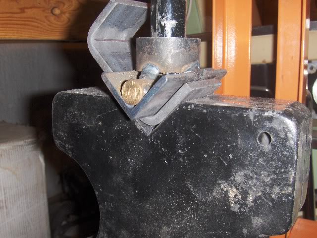
I decided that I'm tired of working on engine stuff, so I decided to tackle the lower control arms today. I had an idea of what I wanted to do but I didn't know if I could bend the bar to make the part so I whipped up a little brake die to fit into my HF 12 ton press.
When I first got the press, I did some rough matching of the press plates that came with it. This was needed to press out the bearings to retrieve the hubs. The press plates are cast, with all the attendant draft the comes with a rough casting. I clamped them together and then ground on them with my 7" angle grinder until they stood up straight and square. I then ground all of the half rounds and vees in them, never knowing when I might need them.
Well, I needed them. After I made the upper brake die, I tried a piece of 1/8" x 2" stock. No sweat. So, I figured, what the heck, I'll try a piece of 1/4" x 2". Still did it without any problems. Didn't even need the extension handle for the jack. The parts came out great.
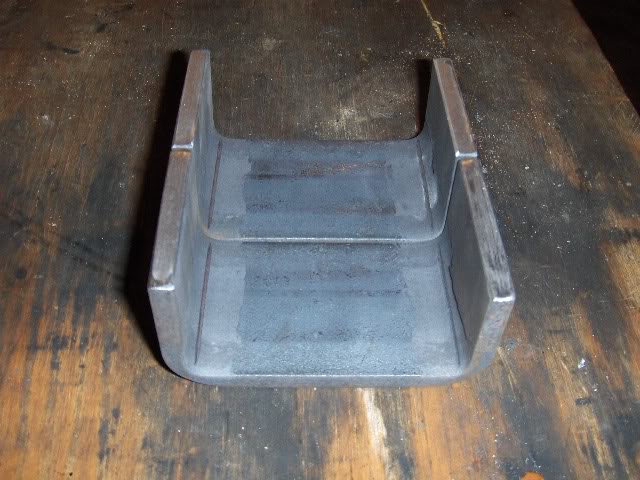
After that, I started on cutting the control arms. The new pieces were 3" wide inside, 1 1/2" long on the legs. I notched the control arms to make them fit tight on the bandsaw, cutting away the outer flange of the outer part of the shock pocket, right up to the outer wall of the pocket.
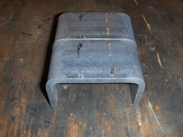
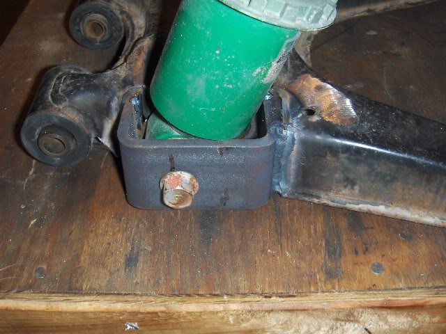
This would now become the inner wall of the shock pocket. It in essence moved the shock 1.9" to the rear. Close enough to the 2" that was bantered about here recently. The control arm was then trimmed back until the new "U" bracket made up a 1.8" inside dimension to match that of the old shock pocket. I then used a long bolt passed through the original holes and threaded into the original nut, clamped the bracket in place and then screwed out the bolt until the head hit the new bracket. I was able to trace around it to locate the new bolt hole. I drilled the hole and then clamped it up and welded it in place.
I still need to add a gusset plate on the bottom to tie it all together, but the way I cut it into the control arm there was a lot of surface area to weld to. Should work fine. I won't need to weld the nut in place as it will be easy to access it through the old shock pocket.
I decided that I'm tired of working on engine stuff, so I decided to tackle the lower control arms today. I had an idea of what I wanted to do but I didn't know if I could bend the bar to make the part so I whipped up a little brake die to fit into my HF 12 ton press.
When I first got the press, I did some rough matching of the press plates that came with it. This was needed to press out the bearings to retrieve the hubs. The press plates are cast, with all the attendant draft the comes with a rough casting. I clamped them together and then ground on them with my 7" angle grinder until they stood up straight and square. I then ground all of the half rounds and vees in them, never knowing when I might need them.
Well, I needed them. After I made the upper brake die, I tried a piece of 1/8" x 2" stock. No sweat. So, I figured, what the heck, I'll try a piece of 1/4" x 2". Still did it without any problems. Didn't even need the extension handle for the jack. The parts came out great.
After that, I started on cutting the control arms. The new pieces were 3" wide inside, 1 1/2" long on the legs. I notched the control arms to make them fit tight on the bandsaw, cutting away the outer flange of the outer part of the shock pocket, right up to the outer wall of the pocket.
This would now become the inner wall of the shock pocket. It in essence moved the shock 1.9" to the rear. Close enough to the 2" that was bantered about here recently. The control arm was then trimmed back until the new "U" bracket made up a 1.8" inside dimension to match that of the old shock pocket. I then used a long bolt passed through the original holes and threaded into the original nut, clamped the bracket in place and then screwed out the bolt until the head hit the new bracket. I was able to trace around it to locate the new bolt hole. I drilled the hole and then clamped it up and welded it in place.
I still need to add a gusset plate on the bottom to tie it all together, but the way I cut it into the control arm there was a lot of surface area to weld to. Should work fine. I won't need to weld the nut in place as it will be easy to access it through the old shock pocket.
Last edited by Stein; 01-19-2010 at 12:10 AM.
Reply
0
0
01-20-2010, 11:43 PM
#49
Elite Member
Thread Starter
iTrader: (46)
Join Date: Dec 2007
Location: Nebraska
Posts: 4,729
Total Cats: 166
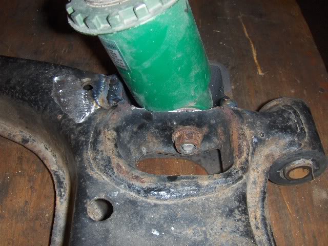
Got the first upper shock mount drilled out today. I jut said screw it and drilled through. By the time I was completely through the first sheet the drill point was already poking through.
If anyone does this, here's a tip:
If you drill all the spots and it doesn't literally fall out, you either missed one or didn't get all of one of the spot welds. I got them all but when I was prying and wiggling it I could see where it was pivoting. After a bit of touch up with the die grinder and a carbide burr on a weld where the drill had walked, the pocket fell out. There is really no adhesive holding them in.
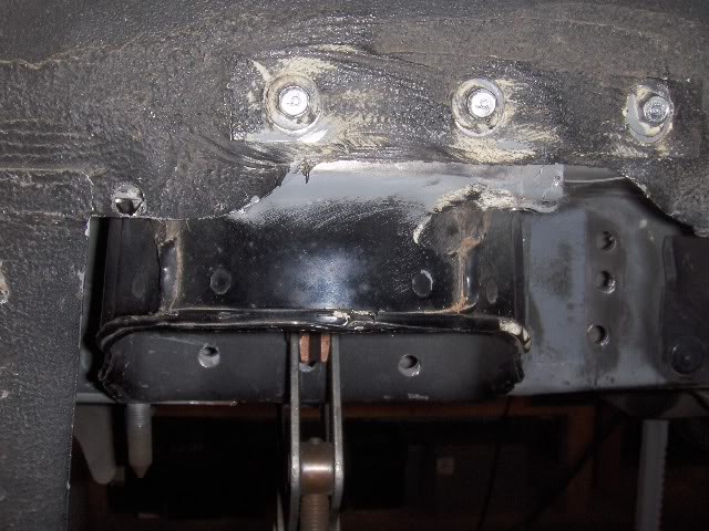
After it is out there is still work to do. Notching on the bottom flange and redrilling the holes for the three upper bolts. Unfortunately, when I moved it back 1.9" to match the bottom, I found that the spot weld spacing was roughly....1.9". You can see where several of the holes almost match up with the original adjacent holes. The only one in the face that hit good metal is the one to the left of the clamp that has my relocation dot on it. I'm going to pull it back off, weld up the holes in the rail and grind flush. That way I can rosette weld the old holes and it will look good.
If anyone does this, here's a tip:
If you drill all the spots and it doesn't literally fall out, you either missed one or didn't get all of one of the spot welds. I got them all but when I was prying and wiggling it I could see where it was pivoting. After a bit of touch up with the die grinder and a carbide burr on a weld where the drill had walked, the pocket fell out. There is really no adhesive holding them in.
After it is out there is still work to do. Notching on the bottom flange and redrilling the holes for the three upper bolts. Unfortunately, when I moved it back 1.9" to match the bottom, I found that the spot weld spacing was roughly....1.9". You can see where several of the holes almost match up with the original adjacent holes. The only one in the face that hit good metal is the one to the left of the clamp that has my relocation dot on it. I'm going to pull it back off, weld up the holes in the rail and grind flush. That way I can rosette weld the old holes and it will look good.
Reply
0
0
01-30-2010, 11:50 PM
#50
Elite Member
Thread Starter
iTrader: (46)
Join Date: Dec 2007
Location: Nebraska
Posts: 4,729
Total Cats: 166
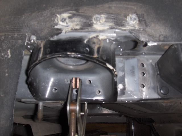
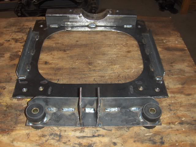
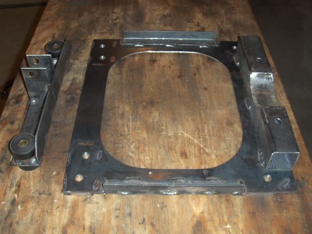
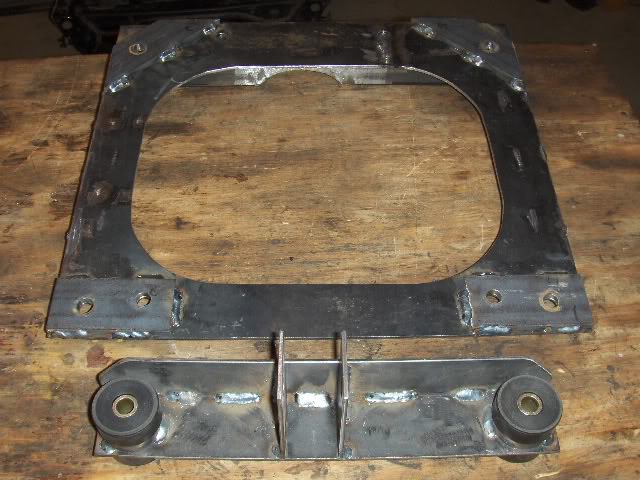
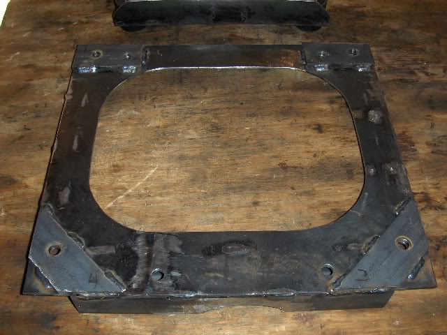
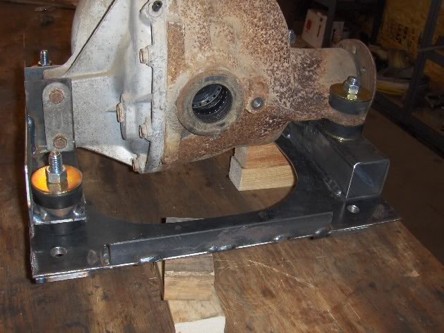
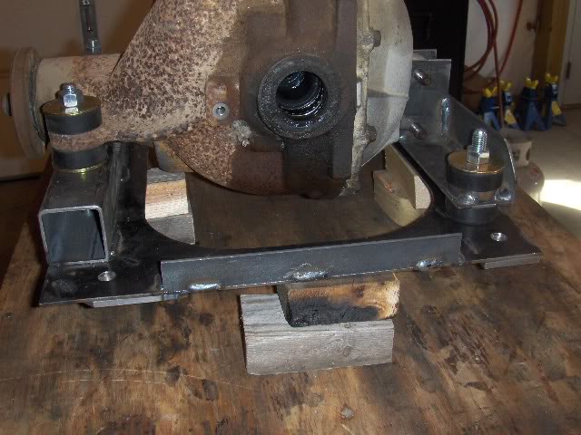
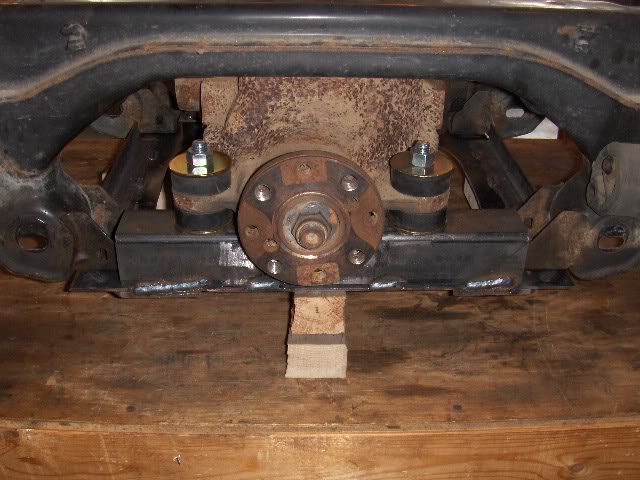
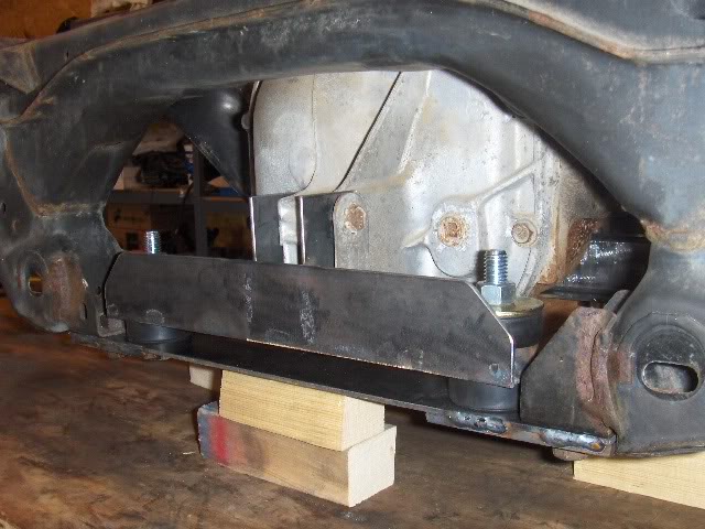
Completed the rear diff carrier today. I suspended the entire diff from the bottom. All mounts are attached to the base plate that bolts to the bottom of the subframe using the four holes that the subrame brace used to be connected to. The diff is mounted on two sets of Energy Suspension diff carrier bushings. They were $20.92 per set from Amazon.com with free shipping.
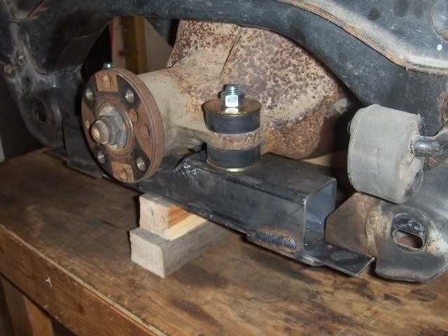
When I measured my other 99, the centerline of the axles shafts was 4.75" above the bottom plane of the subframe pads on the bottom so I carried that dinemsion through to this diff. It worked out that the front needed exactly 2.800" to make it work. The diff bushing and washer were .795" so a piece of 2" tubing was used, notched to clear the snout of the diff.
On the rear, I fabbed a bracket that also uses the same bushings. I mounted them far outboard to offset torque and to get close to the mounting bolts as my lower plate wasn't tied into the upper subframe like BF's mount. They also use a rigid mount welded directly to the frame, whereas I wanted the urethane mounts. The bracket is 1/8" x 2" stock, welded into an angle iron shape. I shimmed up the diff until the flange was perpendicular to the bottom of the plate and set the height there. It pretty much worked out that the bracket sitting on the urethane bumpers without the lower washer just cleared the outside part of the bracket on the diff cover. I had to grind some of the taper in the casting to get it under the bracket.
I then went back and welded some tabs on the bottom to stiffen up the corners where it mounts to the subframe. It ties in the front mount as well as the bolts for the rear mount. These were 1/4" x 2" stock. Final stiffening was to add two 1" angle iron braces running front to rear on the sides of the mounting plate. BF bends the plate up. I didn't have a means to do that so this is the compromise. The center section of the plate was cut out on my Chinese band saw. I had to cut in from the outside to cut out the hole and then I welded it up again.
Reply
0
0

 02-07-2010, 10:33 PM
#55
Elite Member
Thread Starter
iTrader: (46)
Join Date: Dec 2007
Location: Nebraska
Posts: 4,729
Total Cats: 166
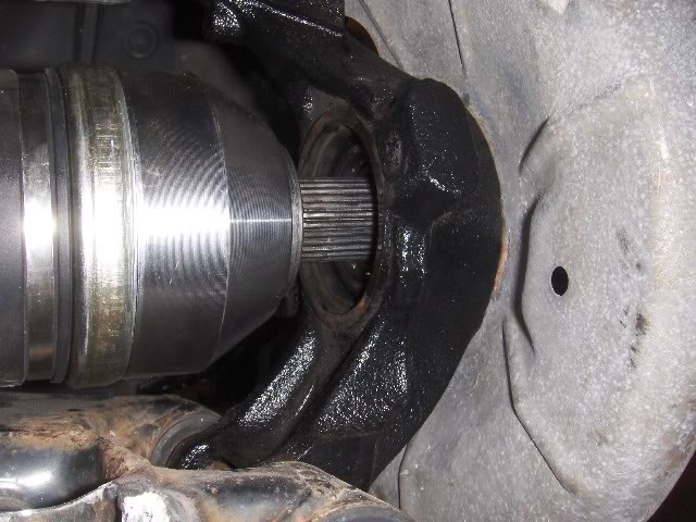
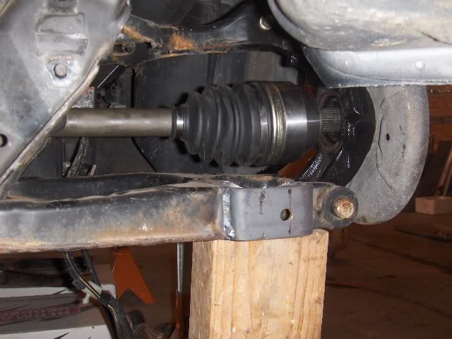
Did a test fit on the rear end today. Pressed in new bearings and assembled the freshly broached hubs. First off was to see if there was any binding on the CV joints. No worries whatsoever. With the shafts horizontal (shortest possible, there is still 1" of travel in the joints so they are right in the middle of their range.
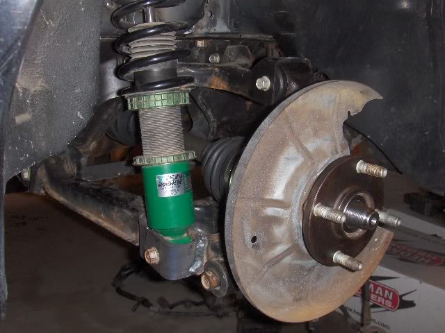
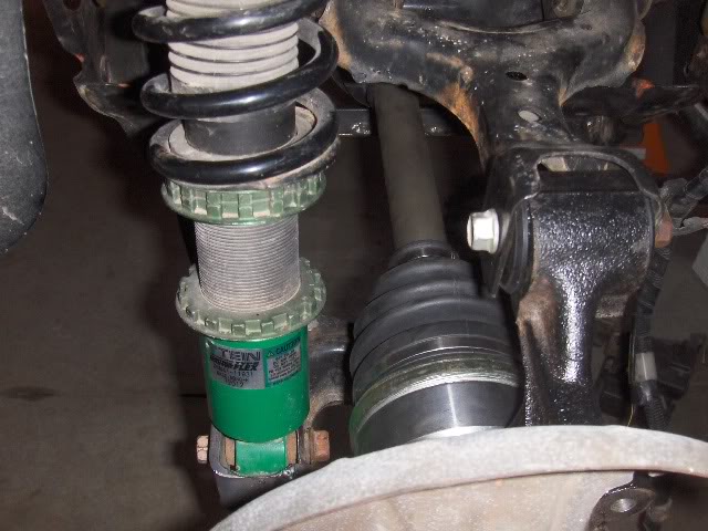
After that I assembled the shocks with the relocated shock pocket. I moved mine back 1.9", as that was the spacing to work with the bottom pocket by moving the shock from the inside pocket to the outside.
Plenty of clearance on the CV boot, even with the large diameter Tein shock bodies.
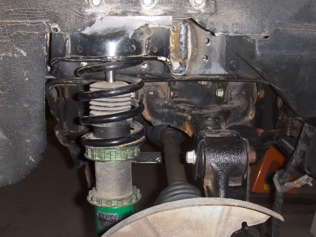
I did run into one problem, though. The FFR inner spline that goes into the diff would not engage the snap ring that retains it in the diff. I pulled it out and compared it to the straight axles that came with the diff. The distance from the end of the shaft to the inner edge of the grove was .500 whereas the other shafts was .420. So, I taped up the shaft to protect it and ground off .080" which ended up being the chamfered area so it made an easy guide. After that I rebeveled the shaft, took a nylon wheel to it to debur and it assembled fine.
That wasn't the end of my problems, though. When I went to remove the shaft I tried to pry it out like normal and it woudn't come. I forced it and it came out but without the snap ring. So, I got to pull everything out and open up the diff to remove two parts of broken snap ring.
Diff is back together and ready to reassemble. So, I think this puts the question of whether the FFR axles will work in our cars to rest.
Total cost in rear end,
$100 used 8.8 diff
$220 Axles
$140 Assembly of diff and gears
Borach hubs $80
Traction Lok and new 3.73's (free-came with donor in a box)
Misc steel that I had laying around
$540 total, plus probably 30 hours labor for everything.
Anyone have a part number for those snap rings?
After that I assembled the shocks with the relocated shock pocket. I moved mine back 1.9", as that was the spacing to work with the bottom pocket by moving the shock from the inside pocket to the outside.
Plenty of clearance on the CV boot, even with the large diameter Tein shock bodies.
I did run into one problem, though. The FFR inner spline that goes into the diff would not engage the snap ring that retains it in the diff. I pulled it out and compared it to the straight axles that came with the diff. The distance from the end of the shaft to the inner edge of the grove was .500 whereas the other shafts was .420. So, I taped up the shaft to protect it and ground off .080" which ended up being the chamfered area so it made an easy guide. After that I rebeveled the shaft, took a nylon wheel to it to debur and it assembled fine.
That wasn't the end of my problems, though. When I went to remove the shaft I tried to pry it out like normal and it woudn't come. I forced it and it came out but without the snap ring. So, I got to pull everything out and open up the diff to remove two parts of broken snap ring.
Diff is back together and ready to reassemble. So, I think this puts the question of whether the FFR axles will work in our cars to rest.
Total cost in rear end,
$100 used 8.8 diff
$220 Axles
$140 Assembly of diff and gears
Borach hubs $80
Traction Lok and new 3.73's (free-came with donor in a box)
Misc steel that I had laying around
$540 total, plus probably 30 hours labor for everything.
Anyone have a part number for those snap rings?
Reply
0
0

 02-07-2010, 11:35 PM
#58
Elite Member
Thread Starter
iTrader: (46)
Join Date: Dec 2007
Location: Nebraska
Posts: 4,729
Total Cats: 166
Thanks man, I'm trying. The DIY thing takes a lot more time that just bolting in a kit. It's fun though. If it wasn't, I'd be bored by now. Back when I satarted, I had planned on going to paint in Feb. That won't happen but I won't see driving weather until April at least. The journey is where it's at. Still, progress every week.
Reply
0
0
03-12-2010, 09:14 PM
#59
Newb

Join Date: Mar 2010
Posts: 25
Total Cats: 0
Love it! I've been searching for a nice in depth fabrication and design thread some of the smaller odds and ends, and you seem to have what I was looking for. I have the identical part setup, so I think I will sell that chunk I was telling you about and start fabbing the 8.8 up.
Reply
0
0
05-05-2010, 04:51 PM
#60
Elite Member
Thread Starter
iTrader: (46)
Join Date: Dec 2007
Location: Nebraska
Posts: 4,729
Total Cats: 166
Yeah, I've been lacking in updates. No visusal progress due to all tedious detail work so no new pics.
Fuel is done - all stainless flex from tank to fuel rail both ways and filters installed.
Most of the wiring is done. Just a few odds and ends and the alternator to hook up.
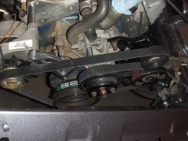
Alternator was moved by using a Marsh-type bracket and then flipping the alternator down where the smog pump was. An idler pulley was installed in the AC bracket to wrap the backside of the belt around the water pump pulley. A turnbuckle mounts to the bottom hole of the alternator for tensioning. Worked out really slick and looks clean. I bored out a Miata 4 rib waterpump pulley ID on the lathe to match the OD of the backsinde of the Ford belt drive pulley and welded it on behind the 6 rib. Then I fabbed up a bracket to mount the Miata PS pump to be driven off of that pulley. THe whole thing packaged nicely.
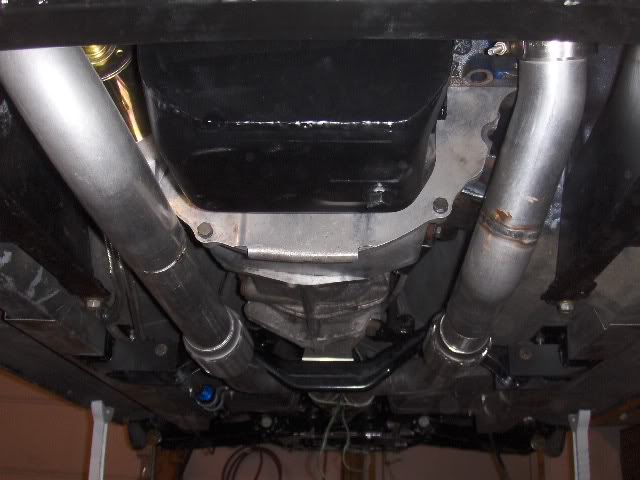
Been working on the exhaust. Everything is being done by me with V-band clamps and mandrel bends. Two V-bands on the headers, one after the merge, one before and after the diff to be able to snake the pipe under the CV. Exhaust is two 2 1/2" into a merge collector into one 3". Columbia River was backordered on all of my 3" U bends to finish so I have been on hold since yesterday. They shipped so I should have them Wednesday and I can finish the exhaust.
Beginnings of the exhaust routing.
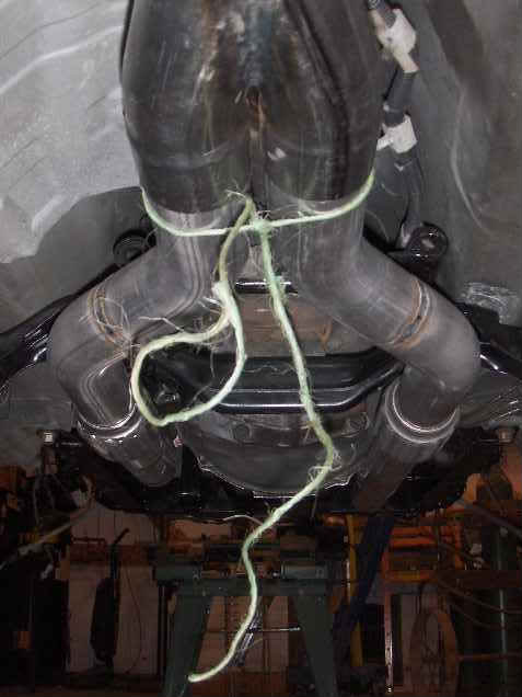
Don't mind the temprary baling twine exhaust hanger. It's not all welded yet. I am a farm boy so I know if this was to be permanent, I'd have to use baling wire instead of baling twine.
Fuel is done - all stainless flex from tank to fuel rail both ways and filters installed.
Most of the wiring is done. Just a few odds and ends and the alternator to hook up.
Alternator was moved by using a Marsh-type bracket and then flipping the alternator down where the smog pump was. An idler pulley was installed in the AC bracket to wrap the backside of the belt around the water pump pulley. A turnbuckle mounts to the bottom hole of the alternator for tensioning. Worked out really slick and looks clean. I bored out a Miata 4 rib waterpump pulley ID on the lathe to match the OD of the backsinde of the Ford belt drive pulley and welded it on behind the 6 rib. Then I fabbed up a bracket to mount the Miata PS pump to be driven off of that pulley. THe whole thing packaged nicely.
Been working on the exhaust. Everything is being done by me with V-band clamps and mandrel bends. Two V-bands on the headers, one after the merge, one before and after the diff to be able to snake the pipe under the CV. Exhaust is two 2 1/2" into a merge collector into one 3". Columbia River was backordered on all of my 3" U bends to finish so I have been on hold since yesterday. They shipped so I should have them Wednesday and I can finish the exhaust.
Beginnings of the exhaust routing.
Don't mind the temprary baling twine exhaust hanger. It's not all welded yet. I am a farm boy so I know if this was to be permanent, I'd have to use baling wire instead of baling twine.
Reply
0
0


