When you click on links to various merchants on this site and make a purchase, this can result in this site earning a commission. Affiliate programs and affiliations include, but are not limited to, the eBay Partner Network.
Also, have you thought about building a bolt on bar (bumper) to replace the section you cut off?
That would tie in the frame rails and reduce movement there as well. Looks like you have room to go over the radiator?
D
Splitime had a thread eons ago that incorporated a tubular crossmember into his V-mount design. Unfortunately most of his pictures have gone the way of the piggyback ECU, but there are some words left.
I had visions of doing just that, but mostly to hold the nose piece in place. Once I got into it I realized how little metal was really up there and how the nose was primarily held on with the bolts at the fender corners and along the top. The factory plastic ducting somewhat holds the bottom in place. Honestly the metal that was cut was so flimsy I could easily twist it 90 degrees with my bare hands, the plastic 5 mph support was adding more support. You have to keep in mind the suspension points all bolt to the subframe, the only forces in the frame rails are the spring / shock mounts. So looking at end of the frame rail the spring and shock is trying to twist the rails and push them up. The section I left along the top would help to reduce twist, but honestly a strut tower brace would do way more, When I removed the fancy aluminum one on this car when I got it I couldn't tell a thing so I just never really worried about anything in front of the towers helping or hurting performance, it's just dead weight to hold the radiator, nose, and headlights up.
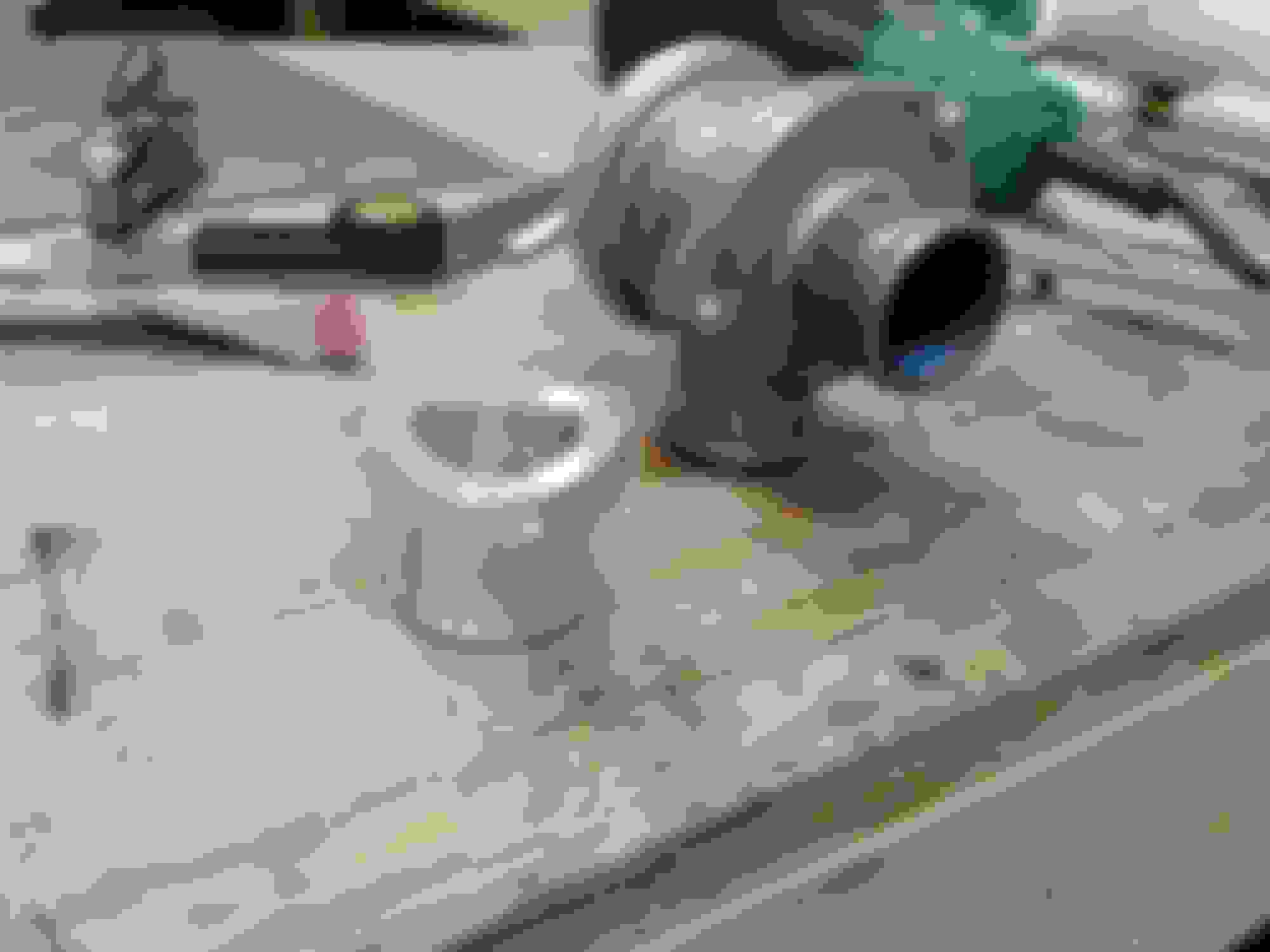
After a nights rest I think I may have goofed on the oil cooler install. Hard to see in this picture but the fittings are on the bottom of the cooler, just no other way to mount a cooler of this size. How real is the chance of air locking the cooler and not utilizing all of it? I know the oil filter has an anti-drainback valve and my whole cooler assembly sits lower than the filter so I shouldn't have to worry about the oil draining out of the cooler every night. My initial thoughts are to pop the cooler loose and turn it on it's side to prime the oil system and it should be fine since there is no way for the oil to drain back to the engine. All of this is assuming the flow isn't enough to carry the air out of the system.
Mountain out of a mole hill? Honestly if it can't mount it as I have it then this cooler won't work.
It's been a source of debate on the forum. if you look at "thepass's" and "hornetball's" build threads they also use your alignment on their race cars. I also have my cooler mounted identical to yours and haven't had any issues with probably 20 track days or so.
If it does bother you, I bet you could lower your top mount enough to clear the fittings. You would need to connect everything and then install everything with the lines on.
Thanks for the input, can't really lower it without it peaking out from under the bumper. Think I'm going to roll with this setup and fix it if it's doesn't work. I would imagine I could see the temp difference with a IR temp gun if I had a sizable air pocket at the top.
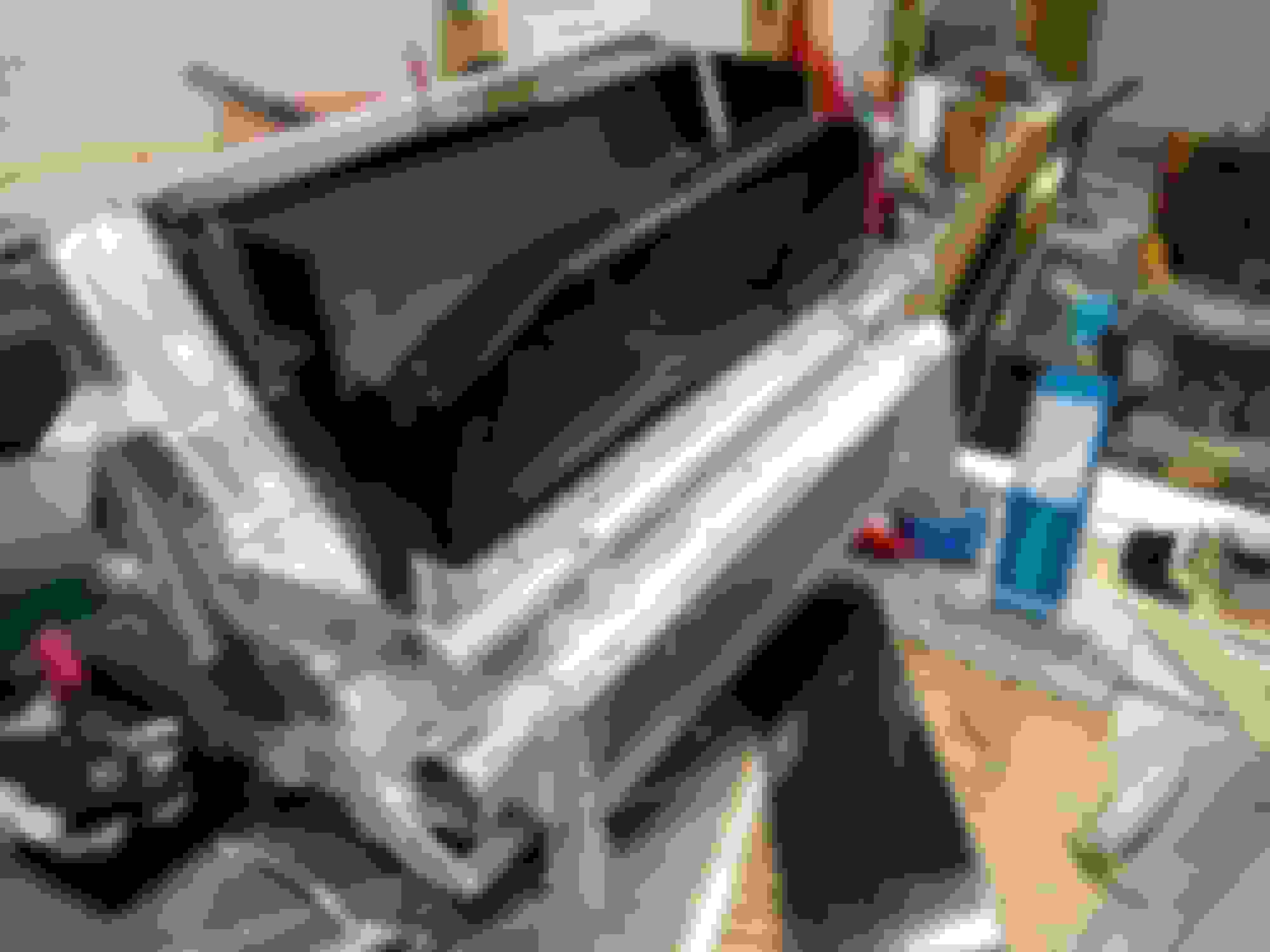
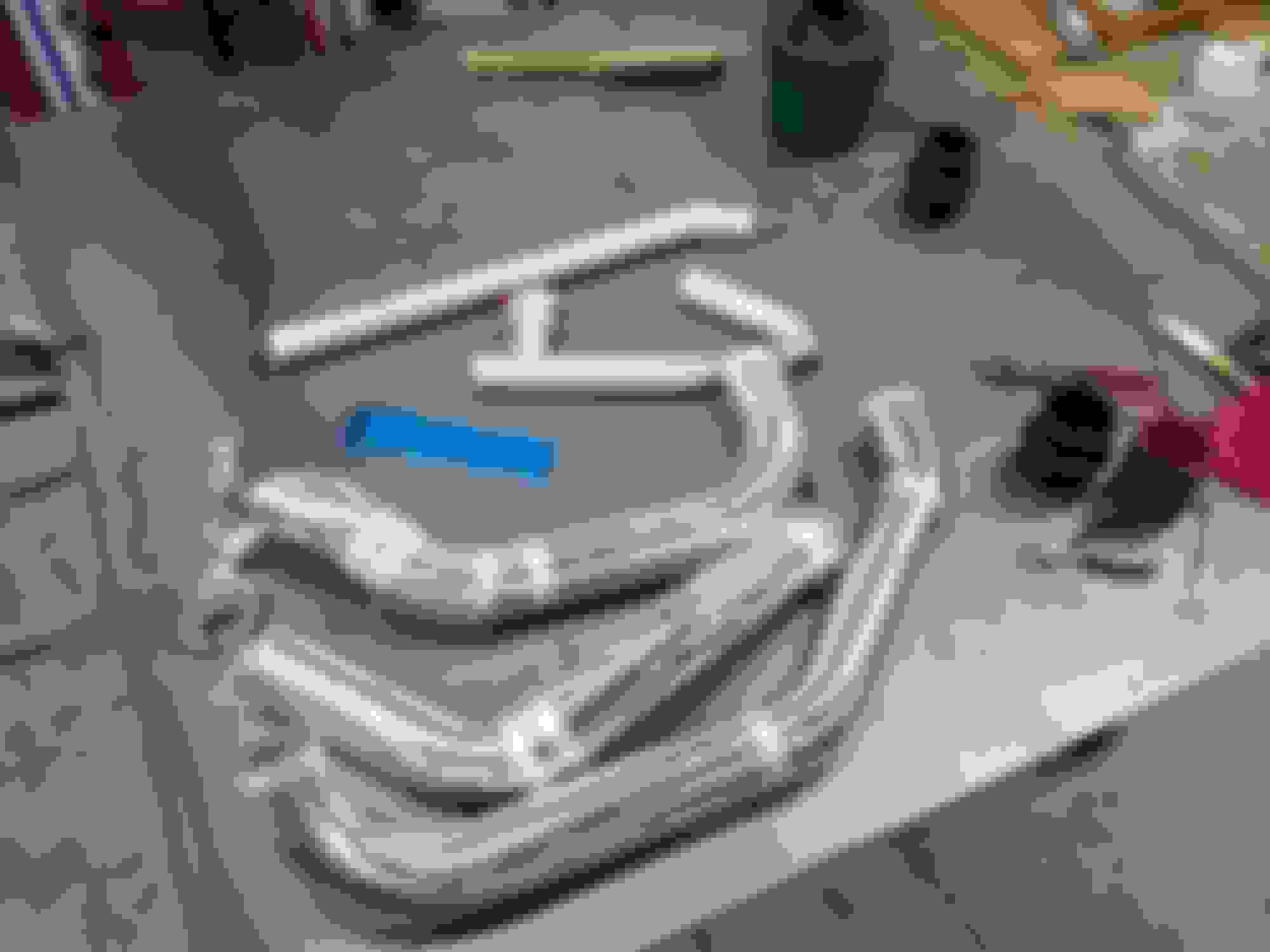
Got just a couple of hours in the garage today but was able to finish up the oil cooler mount and get started on the intercooler piping.
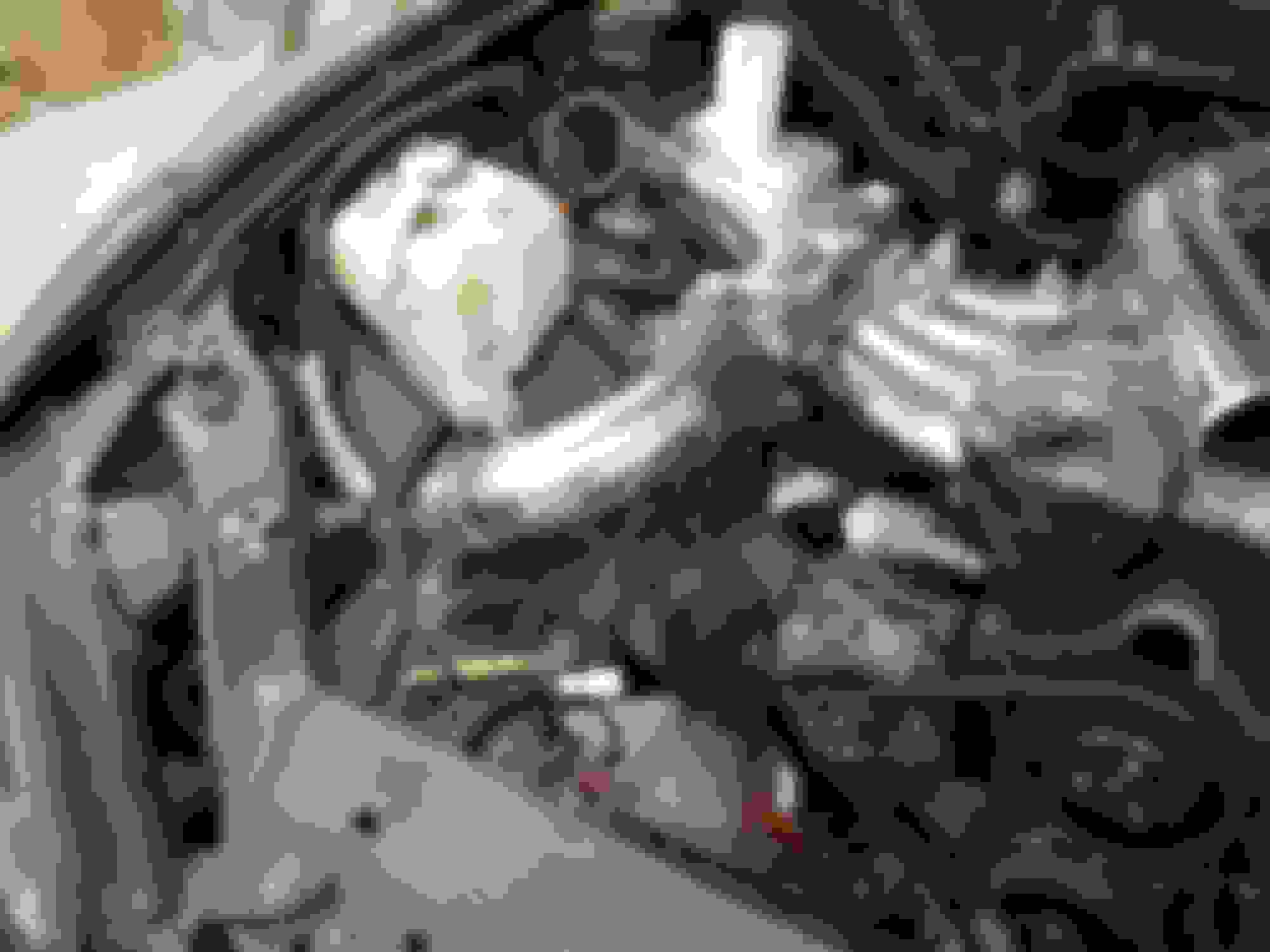
In an effort to keep the area in front of the motor clear for duct work I popped the intercooler piping through the outside of the frame rail right behind the headlight. One of the primary drivers of me doing the short running intake manifold was to get this piping out of the way of the ductwork.
Quite a few subtle bends needed to snake through this hole.
I'll need to line the hole with some cut rubber hose to make sure I don't rub a hole through the piping. I also have a bellow style coupler for the intercooler side to allow for some more movement .
Back to work tomorrow so progress will be slow from now to x-mas, hope to get the rest of the heavy fab and the clutch installed around the holidays and start working on the finer details such as the wiring, programming and multitude of hoses that are needed to actually make this mess work.
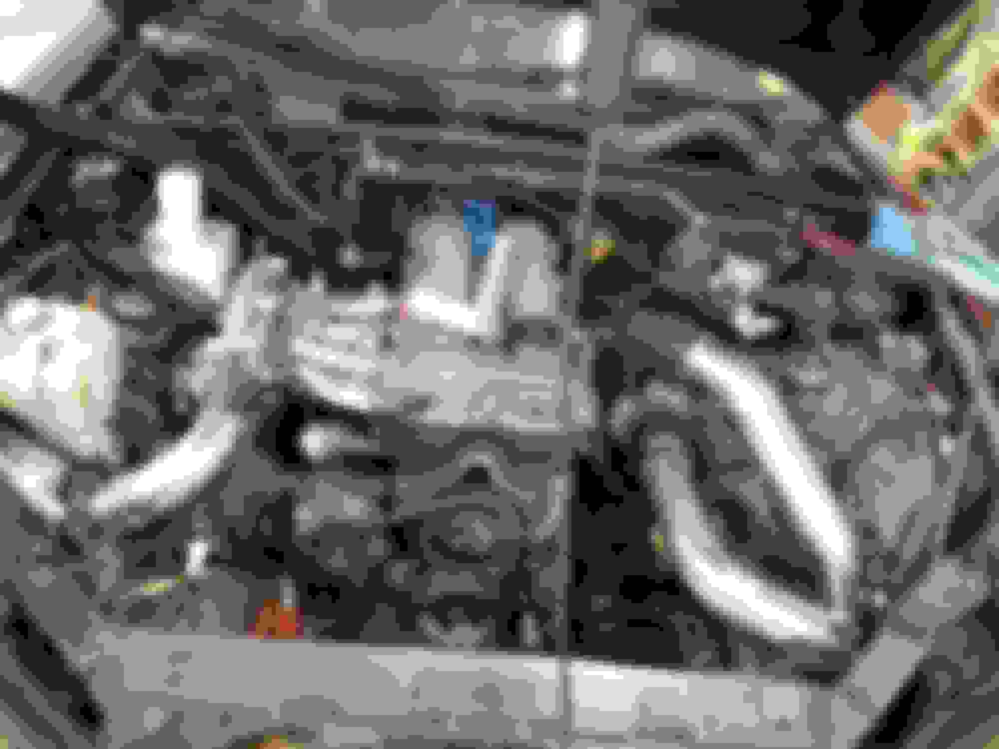
Im pretty sure that's a genuine honda manifold. I've done a half dozen knockoff manifold conversions and something about your manifold looks different, that and the knockoff weld really well. Good job on getting a weld in the runners, thats a tight spot.
So you got me thinking and googling...... Turns out this is a b18c intake and throttle body off a integra type R, not a skunk II as it was advertised. Now this is the most desirable factory intake Honda made and seems to dyno very closely the skunk and blox variants. The throttle body is a 62mm unit which is still a nice improvement over the 55mm miata unit. Hate to have put that much work into that intake but I guess it isn't bad for 100$ and 5hrs of my time.
I used the exact same intercooler in my build. Seems like a pretty good piece for the price. The most I've seen in datalogs is 20-30 over ambient. However, this is on the street, autox, 1/4 mile, no idea how well it would do in a roadrace type environment
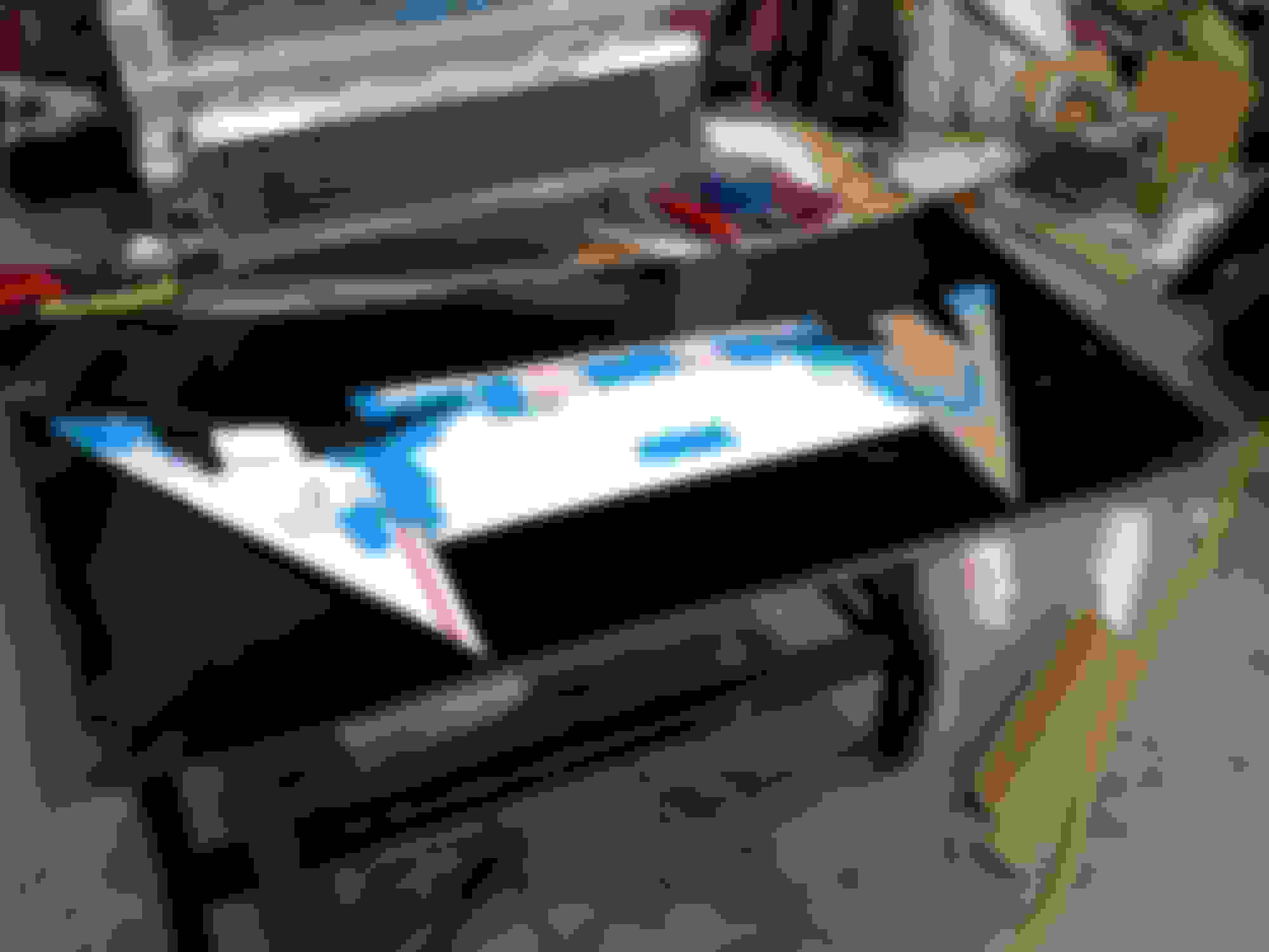
Finally got some time back in the garage, first order of business was to finish my welding table. Piece of 1/4" steel fit the bill nicely.
Last time I had finished up the intercooler to manifold piping, today I turned my attention to the turbo to intercooler and filter to turbo piping. I wasn't real thrilled with my clocking options on the turbo, I experiminted with clocking it with a downward outlet but it just interfered with the lower radiator hose. i could have fabricated around it but I would have had to also rework the wastegate controller as well. In the end I stuck with the strait up BEGI orientation. Like I did on the intake side I popped the piping through behind the headlight on the outside of the frame rail. I had originally intended to run the turbo to intercooler piping down under the frame rail but since I was stuck with the compromised clocking I just made room for two pipes.
As you can see I got into the frame rail pretty good here, I'll make a patch panel to box this in and clean up the ragged sheet metal.
Overall I'm pretty happy with the routing, very strait path with as few bends as possible. I'm very happy I was able to find a way to get the air intake out from under the hood. I always cringe when I see a really well done setup, except for a filter slapped on the end of the turbo. As much time as we spend trying to get intake air temps down there is no reason to start with a 40-50 degree disadvantage.
Spent quite a few hours gluing all this stuff together and getting a few more hard lines made for the radiator.
I'll probably turn my attention to the ducting next, this will make or break this effort if I don't get it right.
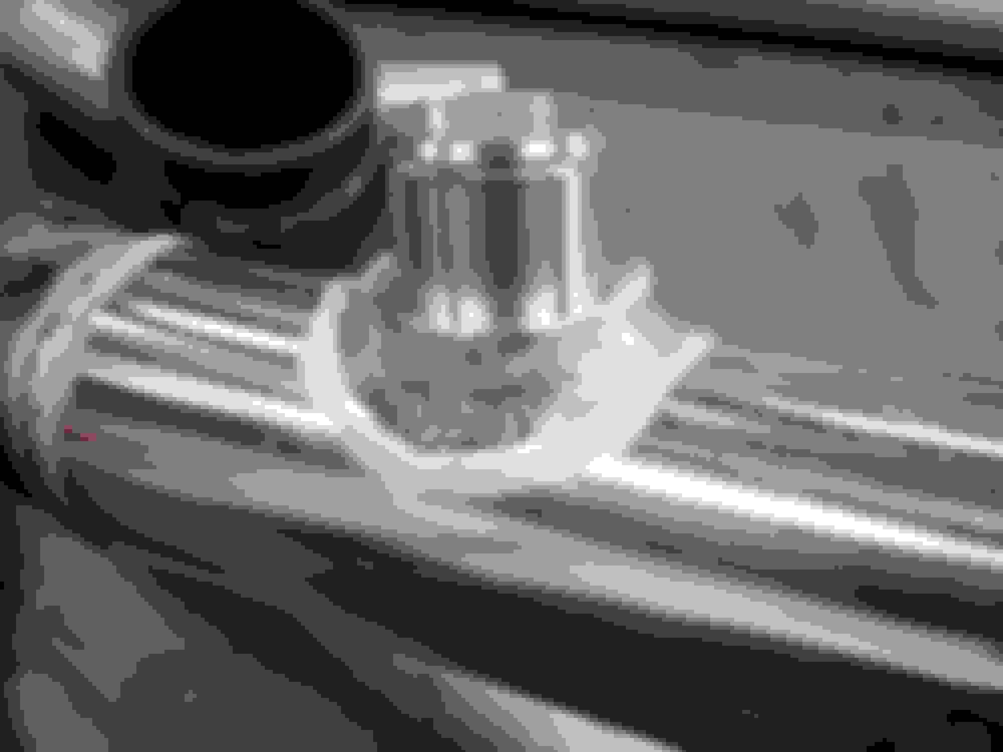
Couple hours, couple odds and ends. Broke out the lathe that's been passed down through the family for 3 generations now to make this nipple that will feed the mistibishi BOV.
I used my tubing notcher to cut the contour before machining.
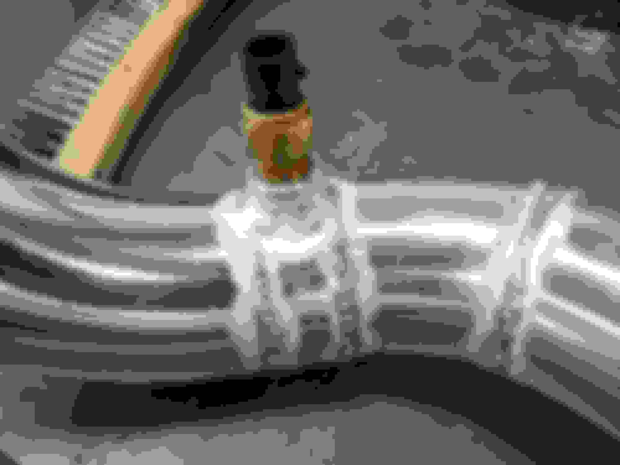
Funny how that I'm finishing up my aluminum welding I finally start getting the hang of it. This shot really shows where I started and where I finished skill wise.
Added the IAC bung as well, more of my early welds compared to my last.
I did the same thing with the oil cooler and ducted the openings on the chin spoiler to cool the brakes, works fine so far.
how are you planing to keep the IC from filling with little rocks, tire chuncks etc being in a horizontal position and on the bottom of the opening like that? May not be an issue but you may need some fine mesh in the mouth of the bumper to keep that stuf out
That's a good point, I'll have to see how bad it is. I really don't like mesh, even an open sections knocks flow down 10 to 20%. Might have to put some ports in the ducting to be able to blow it out from the back side.
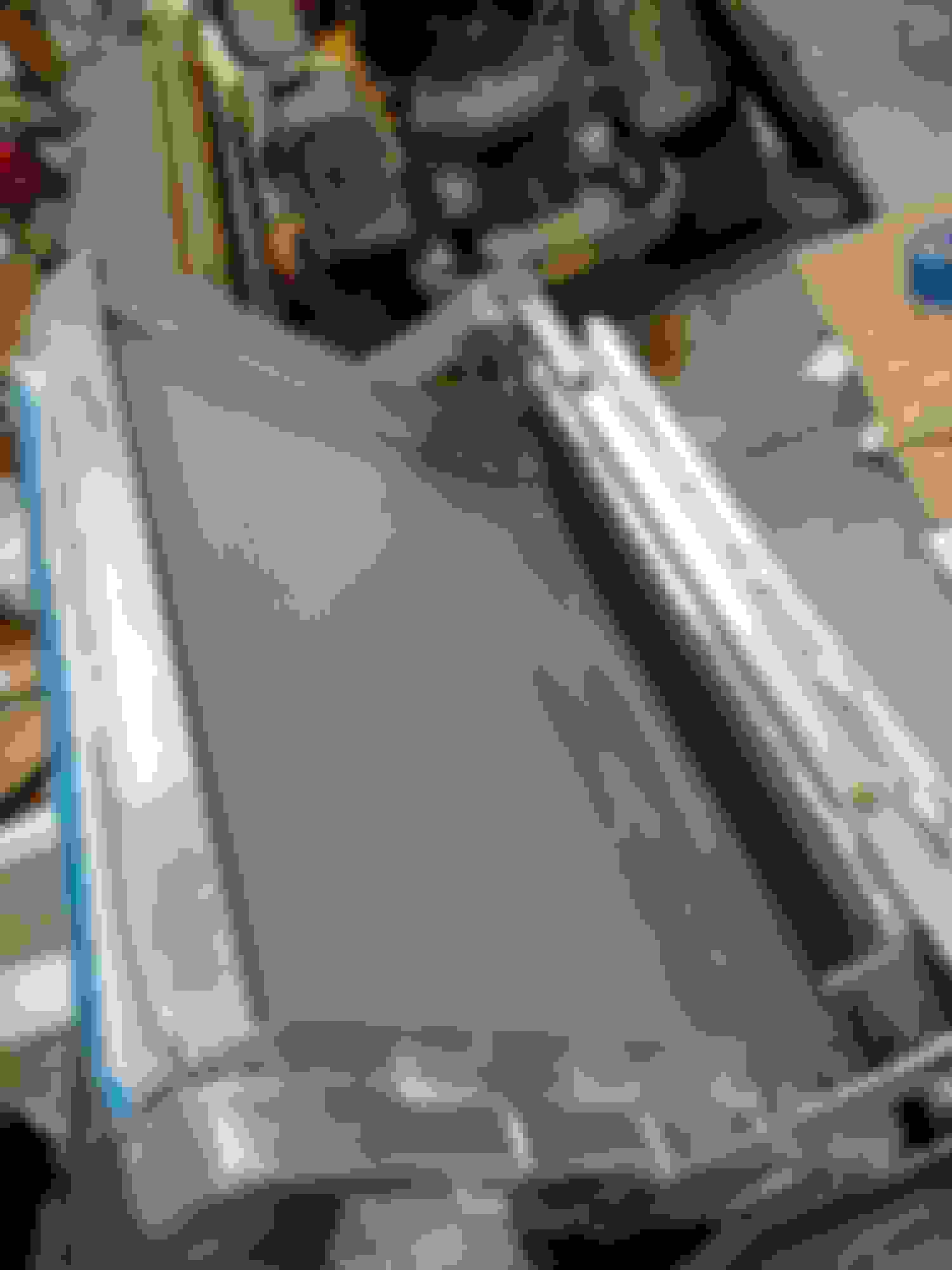
Got started on the ducting, like I mentioned earlier ducting will make or break this setup. Because neither heat exchanger is pointed into the air stream I'm relying solely on pressure differential between the front and rear of the cores. Since air will always follow the path of least resistance I couldn't allow for any leakage.
I started by welding aluminum plate to the perimeter of both the radiator and intercooler which will give me a nice place to rivet the ductwork to. trying to get the ductwork to seal decently to the radiator and figuring out a mounting solution would have been a nightmare so why not attach it directly to.
Next I got busy with some flat rate templates, I must have had the nose piece on and off 20 times.
The nose ended up being much closer to the heat exchangers than I had envisioned, so flaring out the ductwork from the 23" core to the 31" nose opening was proving to be a daunting task......much easier to work in strait pieces. So I think I figured out where my brake ducting is going.
So I ended up with this mess of a template.
The black plastic you see is the HDPE plastic you can get from Free Shipping @ Speedway Motors, The Racing and Rodding Specialists and a few other circle track suppliers, I made door panels out of the stuff as well. At least it looks much cleaner once I got it cut out.
Bent with a little heat from a propane torch and riveted with L brackets in a few corners.
Here it is in place with a couple of cleco's, the rest of the waviness should clean up once it's completed.
Hard to see in these pictures but the plastic hugs the opening in the nose quite closely, I had thought of using some kind of wetherstrip edging to seal it completly but it's snug enough I may just let it go as is. I went ahead and let the vertical dividers run to the outside of the nose to help keep the high pressure air from spilling over into what will now be the brake duct inlets. I'll get it fitted back up for a picture soon.
One last photo of the water inlet and outlets now that they are in place.......they look a bit spindly but are actually quite robust.


 11-26-2016, 05:01 PM


 0
0


 real purty.