
GM IAT in intercooler


I have put together the diypnp now I am installing all the parts.
So I read in some other post about IAT placement.
I got the bung and can weld so I could put it in the piping running to the TB.
I also saw some one mention drilling and tapping the cold side of the intercooler.
Is that the best option and if so can some one give me some detailed instuructions.
Where do you choose on the IC to drill.
Do you use a standard drill and tap never done aluminum before.
Anyone know the size/ thread pitch of a gm iat.
Does anyone have any pics.
Thanks
I dont know what I would do with out this board.
Reply
 0
0

0
GM IAT is 3/8 NPT. I just use a standard tap that I purchased at a hardware store for anything I've done w/tapped aluminum.
However, after I discovered this, I've stopped dicking around with tapping for IAT. Costs less/as much as a good tap anyways.
However, after I discovered this, I've stopped dicking around with tapping for IAT. Costs less/as much as a good tap anyways.
Last edited by blaen99; Jan 19, 2012 at 01:08 AM.
Reply
0
0
All-round "Good Guy"

Joined: Dec 2009
Posts: 1,036
Total Cats: 266
From: Brisbane, AUSTRALIA
Use a Quicktap connector to add a barb to the intercooler->TB hose (http://www.atpturbo.com/mm5/merchant...Category_Code=) - a LOT easier than adding a barb to a metal pipe.
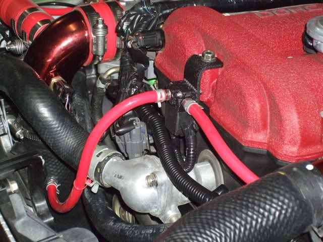
In hindsight, I would have preferred to install the connector a little closer to the TB elbow (ie. higher up the hose) since it was a bitch getting it in there.
In hindsight, I would have preferred to install the connector a little closer to the TB elbow (ie. higher up the hose) since it was a bitch getting it in there.
Reply
0
0

I've done the intercooler method with mine. I'm not sure that it's the "best", but it's the easiest, since a lot of people like aluminum intercooler piping and hardly anyone has a TIG welder, so it's also the cheapest/quickest.
Reply
0
0


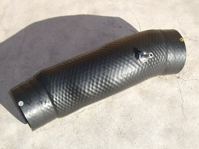
first time the IAT bung mounted on a short section of Al pipe immediately up stream of the throttle body
the second time the IAT was tapped into the rear of the plenum of the intake manifold
you want to measure the temperature as close to the piston as you can, being mindful of heat soak
the second time the IAT was tapped into the rear of the plenum of the intake manifold
you want to measure the temperature as close to the piston as you can, being mindful of heat soak
Reply
0
0

Use a Quicktap connector to add a barb to the intercooler->TB hose (http://www.atpturbo.com/mm5/merchant...Category_Code=) - a LOT easier than adding a barb to a metal pipe.
.
.
Reply
1
1
All-round "Good Guy"
Joined: Dec 2009
Posts: 1,036
Total Cats: 266
From: Brisbane, AUSTRALIA

Reply
0
0

Joined: Sep 2005
Posts: 34,433
Total Cats: 7,549
From: Chicago. (The less-murder part.)
Yes.
Detailed instructions:
1: Pick up drill with hands.
2: Insert drill bit into drill (see instructions included with drill for exact procedure.)
3: Attach drill to source of electrical power.
4: Position drill with pointy part facing intercooler end-tank, perpendicular to surface.
5: Squeeze trigger on drill with finger.
6: Press pointy part of drill against intercooler end-tank until penetration occurs.
7: Withdraw drill from intercooler.
8: Set drill down.
9: Pick up tap handle and tap.
10: Insert tap into tap handle.
11: Position tap against hole created in step 6.
12: Using hand, turn tap clockwise (as viewed from non-sharp end) while applying pressure against intercooler end-tank.
13: Once tap has penetrated to the desired depth, remove by turning counter-clockwise.
14: Lay tap down on workbench.
15: Pick up temperature sensor.
16: Position temperature sensor against hole in intercooler.
17: Install temperature sensor into intercooler by turning clockwise until snug.
18: Install intercooler into car.
19: Attach electrical connector to temperature sensor.
20: Profit.
Any place on the "cold side" end-tank where it will fit.
Yes. Just go slower, and back out the tap to clean the threads a little more frequently. No cutting oil needed.
3/8" NPT.
and if so can some one give me some detailed instuructions.
1: Pick up drill with hands.
2: Insert drill bit into drill (see instructions included with drill for exact procedure.)
3: Attach drill to source of electrical power.
4: Position drill with pointy part facing intercooler end-tank, perpendicular to surface.
5: Squeeze trigger on drill with finger.
6: Press pointy part of drill against intercooler end-tank until penetration occurs.
7: Withdraw drill from intercooler.
8: Set drill down.
9: Pick up tap handle and tap.
10: Insert tap into tap handle.
11: Position tap against hole created in step 6.
12: Using hand, turn tap clockwise (as viewed from non-sharp end) while applying pressure against intercooler end-tank.
13: Once tap has penetrated to the desired depth, remove by turning counter-clockwise.
14: Lay tap down on workbench.
15: Pick up temperature sensor.
16: Position temperature sensor against hole in intercooler.
17: Install temperature sensor into intercooler by turning clockwise until snug.
18: Install intercooler into car.
19: Attach electrical connector to temperature sensor.
20: Profit.
Where do you choose on the IC to drill.
Do you use a standard drill and tap never done aluminum before.
Anyone know the size/ thread pitch of a gm iat.
Reply
2
2
Thanks Joe. I now understand. Any place on the cold side is thick enough to drill and tap so I will prob just go with the flat part where it transitions to the tube outlet.
Reply
0
0
I remember people having issues with their sensors right behind the fans. Many reported heat soaking issues which cause horrible leaning for few minutes after a semi hot start.
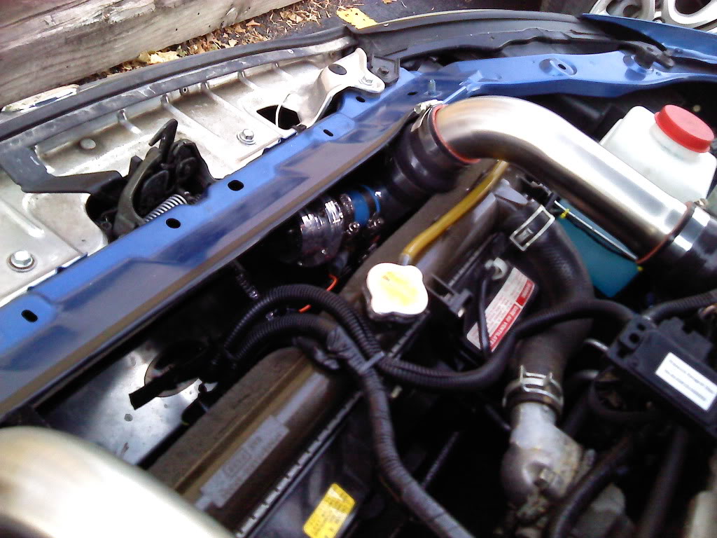
I'm running over the rad setup so i tossed my pipe right above the IC.
I'm running over the rad setup so i tossed my pipe right above the IC.
Reply
0
0
Joined: Sep 2005
Posts: 34,433
Total Cats: 7,549
From: Chicago. (The less-murder part.)
Yeah, this is one area where "cheap" intercoolers with cast-aluminum end tanks are quite nice. On my fleabay unit, I was able to get about two threads' worth of mating surface on the flat, diagonal portion of the tank. It's not much, but there's also not a lot of pressure or mechanical load here. Go slow, use some RTV silicone to seal it all up, and just use common sense. This isn't hard, nor is the placement of the sensor an especially critical task. Just try to locate it someplace where it's not going to obstruct the flow of raccoons through the inlet in the bumper cover and you'll be fine.
Reply
0
0

I'm Miserable!
Joined: Jun 2009
Posts: 1,866
Total Cats: 0
From: albany, ga
More then likely they were running a Megasquirt and IAT correction was leaning it out. Their IAT default correction just mess around like hell above 80f and leans out to no end basically. Its not IAT placement causing the lean issue. Currently I have mine before the compressor inlet seeing up to 150f+
Reply
-1
-1
More then likely they were running a Megasquirt and IAT correction was leaning it out. Their IAT default correction just mess around like hell above 80f and leans out to no end basically. Its not IAT placement causing the lean issue. Currently I have mine before the compressor inlet seeing up to 150f+
Reply
0
0

Thread
Thread Starter
Forum
Replies
Last Post
StratoBlue1109
Miata parts for sale/trade
21
Sep 30, 2018 01:09 PM
Mikel
MEGAsquirt
4
Sep 28, 2015 04:46 PM


