When you click on links to various merchants on this site and make a purchase, this can result in this site earning a commission. Affiliate programs and affiliations include, but are not limited to, the eBay Partner Network.
Very curious about your feedback on the oil-less turbo. I haven't really heard of them before your post and was looking into it. I've been debating a dual front mount setup with GT2560's. The exhaust flanges/mounts seems like they would be easy to machine and set it up like the LF4. I've got way more room than you since it is an exocet. What are your thoughts on that too?
Very curious about your feedback on the oil-less turbo. I haven't really heard of them before your post and was looking into it. I've been debating a dual front mount setup with GT2560's. The exhaust flanges/mounts seems like they would be easy to machine and set it up like the LF4. I've got way more room than you since it is an exocet. What are your thoughts on that too?
If I had the room I would have 100% gone with a SC and a crank mount at that. A twin turbo setup would be fun as hell but I'm not sure I would go that route if I planned to track the thing. I've been in a few TT cars and the transition to boost is generally too much too soon which makes the car a hand full coming out of corners and on long sweepers. I'm sure you could make it manageable with a really good boost controller though. I though for sure the LFX was going to be a pain in the *** and fight me the whole way on the tuning side of things but the motor actually seems to love a little boost. Guessing that is why they decided to use it in the ATS V. I think if you decide to TT yours, I would for sure change out the rods and pistons to LF4 hardware because the prices are really pretty damn affordable from the dealer.
FWIW, The LF4 & LF3 use the same pistons/crank, and the only differences between an LF3 is the titanium rods in the LF4,
and the LF4 turbos use a specific turbine wheel that is very light, but they are otherwise identical housings and compressors.
They use the same ECM, heads, cams, pump etc.
The LF4 is just 2 different PN's and a different tune to run higher boost.
Interesting, thanks for the info! Very curious to see what Ryan has up his sleeve, but from what I have seen the Overkill supercharger kit seems like a great piece of hardware, albeit expensive. I had plans to go E85, but there are only two gas stations in Austin that carry it and the closest is 30 minutes away from me. If you ever make it to Austin please hit me up. Would love to chat more.
How are the Vr1's holding up? I had traction issues at 250whp, so ended up going to RC1's in the hopes that I can put the power down. What rear gears are you running?
I am running a LSD 3:23. Damn thing was HARD to find too in Colorado.
So far I for sure get better traction over the NeoGens and they seem to be providing solid traction. They seem to "float" a bit more than I would like but I need to check my alignment again before I blame the tires.
I pulled the hell out of my flares before I painted the car and I just need a little bit more to clear these.
Will hit you up for sure if I am up towards Austin and do the same if you find yourself down here in Houston.
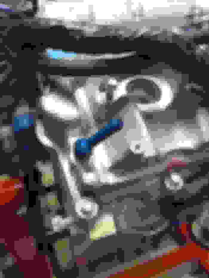
I was able to seal up the v band leak today with one of these. Worked great and I will be putting one in every v band I install going forward. I have tried several ways of welding them on but unless you are willing to spend the time to make a jig to keep them from warping you will never get them to seal properly. These gaskets should do the trick for 99% of the leaking v bands out there. I also have found that if you use some copper anti-seize in the band and on the threads of the t bolt they seem to seal up MUCH easier.
Now on to a front splitter and full flat bottom....
Sorry for not getting dyno results in the thread sooner, but my relationship status with the miata went from "its complicated" to "married with dog and kids in the suburbs". It is currently getting a full cage, fire system and various other items.... As soon as those are done, I have an appointment with a professional tuner to get it 100% dialed in and actual HP number to see where we landed.
Took her out for her first track day since the cage and turbo and this is a COMPLETELY different car now with the cage. I expected the chassis to be stiff but wasn't sure what that would really mean or feel like. Before the car would flex a bit and it was clear when you were on the verge of the tires cutting loose and you could play in a pretty wide safe zone of control. The car now has significantly more traction until it has ZERO! Caught me off guard the first lap I really started to push the car. By the end of the day I was starting to get used to it so it will just take me learning to feel new zone in the car. I also had a noticeable amount of understeer which the car never really had before. Going to play with the aero and alignment a bit to see if we can remedy that.
The turbo is adding a fair bit of heat into the cooling system. Pushing the car really hard in the heat of the afternoon pushed the temp gauge up to 260. I exited that session and skipped the next one to let the car cool off.
Overall the car did pretty well in her first real shakedown. After getting the car back home and up in the air I looked over EVERYTHHING. I found one bolt that was trying to come loose and one spot where the chassis was rubbing on an intercooler pipe. I fixed those up and set out to fab up a cooler for the turbo in the back of the car.
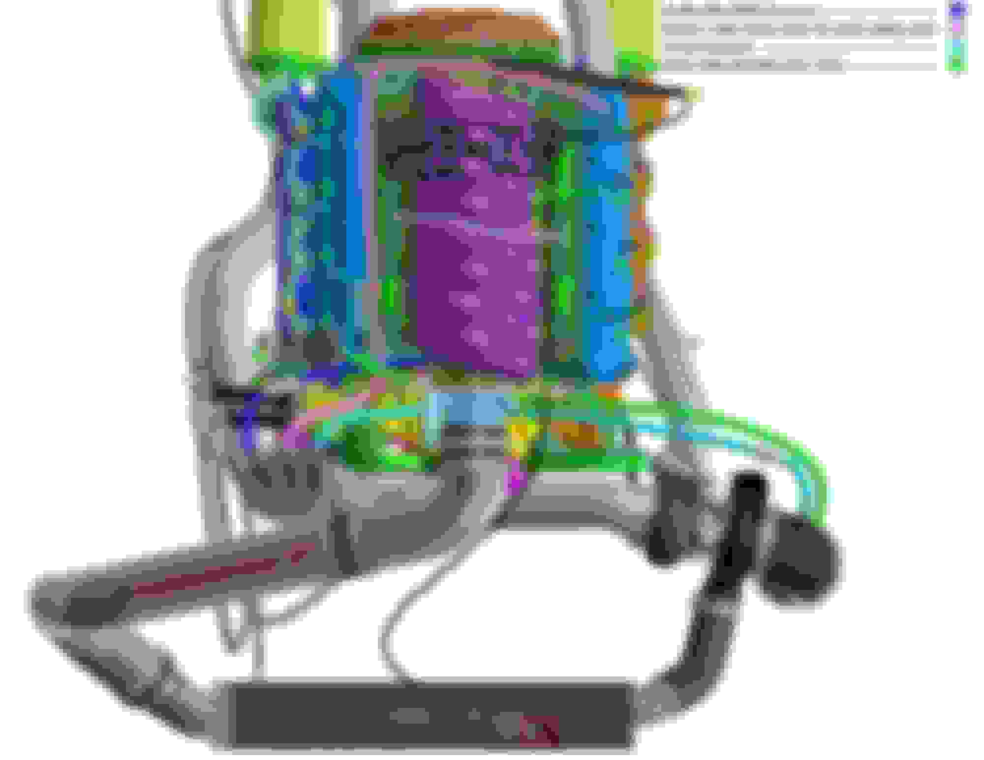
I ended up ordering one of these coolers. I knew I wanted it right after the turbo before the coolant started its journey back to the engine but wasn't sure if I wanted it in the trunk lid, like a Porche, or the license plate area.
The lid would have been pretty straight forward but would have required a support structure to be fabbed up in the trunk.
The license plate area looked like a near perfect fit and I could mount the cooler to the body. I wasn't sure how the aero would impact the cooler in the ducktail and someone guided me to Emilio's "Vegas" build here. In his buid he placed a trans and diff cooler in the plate area to take advantage of the low pressure behind the car but he is also feeding the fans from the rear wheel well. Made good enough sense to me so I decided to mount the cooler in the license plate area.
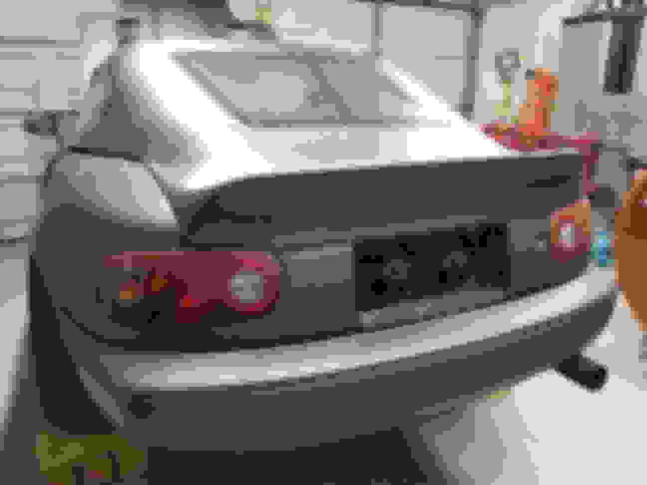
Here is the end result and I will post up the resulting temps after the next track session.
Next up is the front aero and GT 250 wing. I found a cheap front bumper locally and had most of the other stuff needed to build an air dam and frame mount the GT 250 so both are already under way...
Nothing special and both are well documented elsewhere. I have most of the air dam done and just need to trim the splitter 3" out and I can get started on the rear wing.
Just got caught up on this. Surprised by one detail: that the air sensor is just before the throttle body. My understanding was the sensor should be pre-compressor. Looking at your setup I see the obvious problem there though - your filter is on the turbo, so nowhere for the sensor to go pre-turbo. Any complications from this?
Then again, I believe that sensor is responsible for IAT and MAP, and for both of those you'd want the sensor where you have it...
This is my first adventure of FI a NA motor so I have ZERO idea if the way I have set my system up is the "right" way or not and as you know, there is little to nothing out there on it other than the LF4. All I know is what I have done seems to work and it works really well. The MAF picks up air volume and temp only. The MAP is separate and on top of the manifold. So far I have not seen the max frequency hit on the 2 bar map that comes in the LFX from the factory but I have a 3 bar one if you end up needing it or just want to try it out.
The one thing that really got me sideways was my catch can configuration. The maker of the can advised a configuration that would allow un-metered air into the engine. When I asked them if I understood their drawing correctly, they assured me that a tuner could adjust for the extra air and everything would be fine. Bottom line, I had to do away with the vacuum source to the can and I have a line that goes all the way to the intake of the turbo as the only source of vacuum for evacuating the crankcase gasses. Last track day I pushed the car HARD and I had no issues or signs of excessive crankcase pressure that would indicate I needed to get more air out of the engine.
You can drill out and tap the passenger side valve cover outlet at the back where the stock outlet valve is pretty easily. I went with a npt to 3/8 barb on mine, but you could go bigger.
I'm also running the Tracy Lewis clean side air/oil separator and a catch can. The TL clean side separator only allows metered air when you cap the driver backside vent tube.
Griff, do you have the PN for the 3 bar map sensor? I'd prefer to have as many options on hand as possible when we get to dyno tuning.
Crankcase ventilation when you add boost to the mix seems to be a popular subject for confusion and misinformation over on the Camaro forums. I have 2012 plastic valve covers (for weight) which makes adapting fittings a little trickier but I've drilled out the stock PCV to match the later 2013+ hole size. Current plan is to keep the routing of the ventilation system similar to stock, with two air/oil separators, one in-line with the dirty side PCV to IM line and the second in-line with the clean side VC to intake tube pre-supercharger. Typically the clean side line needs to go post-MAF sensor, so if the MAF gets moved from pre-compressor to post-compressor then that clean side ventilation line similarly needs to move, which it looks like you did griff. I'll have to marinate on where I want to put the MAF... I might just put a MAF port and AN bung in the intake tube as well as the charge pipe by the throttle body so I can try both.
LukeG - there's one thing I don't like about the TL oil cap adapter: The standard vent port has a baffle under it inside the valve cover. The oil fill cap hole doesn't have this sort of baffle (there's a splash baffle there but it's not quite the same). I would expect more oil down that line when using the cap adapter rather than the standard port.
I had a similar setup before the turbo was added, but when you run boost you will put a check valve in that line, and the brake booster, so that you don't pressurize your crankcase. Once that is done, the block is essentially capped off so any blow-by is trapped until you get out of boost and provide vacuum again. The vendor provided me this:
So the idea is that when the check valve is closed the line from in front of the turbo will provide the vacuum but when vacuum is reapplied this will allow un-metered air into the system. I think in the LS system this is not a big deal thanks to the VE tables but in the E39 ECU there are no VE tables. EVERYTHING is calculated based on variables. HPTuners created a "Virtual VE" table but apparently I am not smart enough to operate that table with un-metered air in the system. I fought my hot/cold idle FOREVER until I welded up a new MAF tube that didn't have the post MAF port for vacuum and ran the breather lines through the catch can back to the front of the turbo. Now ALL air is metered by the MAF and it runs like a top.
So at this point I am only really just pulling a small amount of fresh air through the crankcase at idle and "more" under boost thanks to the line that goes from the valve cover back to the turbo inlet.....although I'm not sure how much yet. On the last track outing, I set up an oil trap on the rear driver side port (normally my clean air source) to see if anything was blown out as a result of the system not pulling enough case pressure from the turbo and there were no signs of blow-by pressurizing the case with 3/8 lines. On the other hand, I could easily get a cup out of the catch can after a hard day of driving and now it is pretty dry so I'm not 100% sure I have the winning setup. I guess I'm going to run with what I have until someone smarter, like you or Ryan, figure out a better way to do it. ;-)
DAMN!!!! I just realized I have created, YET ANOTHER, thread on how to NOT properly ventilate your LFX crankcase under boost.....
Griff, do you have the PN for the 3 bar map sensor? I'd prefer to have as many options on hand as possible when we get to dyno tuning.
Crankcase ventilation when you add boost to the mix seems to be a popular subject for confusion and misinformation over on the Camaro forums. I have 2012 plastic valve covers (for weight) which makes adapting fittings a little trickier but I've drilled out the stock PCV to match the later 2013+ hole size. Current plan is to keep the routing of the ventilation system similar to stock, with two air/oil separators, one in-line with the dirty side PCV to IM line and the second in-line with the clean side VC to intake tube pre-supercharger. Typically the clean side line needs to go post-MAF sensor, so if the MAF gets moved from pre-compressor to post-compressor then that clean side ventilation line similarly needs to move, which it looks like you did griff. I'll have to marinate on where I want to put the MAF... I might just put a MAF port and AN bung in the intake tube as well as the charge pipe by the throttle body so I can try both.
LukeG - there's one thing I don't like about the TL oil cap adapter: The standard vent port has a baffle under it inside the valve cover. The oil fill cap hole doesn't have this sort of baffle (there's a splash baffle there but it's not quite the same). I would expect more oil down that line when using the cap adapter rather than the standard port.
 04-19-2019, 01:13 PM


 0
0


 Awesome build man, car sounds like a blast. It is crazy the difference a cage makes in a car, especially a floppy miata.