
1.6 ECU pin 1U - Dimmer for MTX-L?


Junior Member
Joined: Jan 2015
Posts: 169
Total Cats: 7
From: San Jose, CA
Reply
 0
0

0


omfg dude. read the manual that came with your WBo2.
does it say anywhere that you should twist together output 1 and output 2 and send two separate programmable outputs to the same single place?
you bumped a nearly 1 year old thread to ask a silly unrelated question that shouldn't be legitimized with a serious response.
does it say anywhere that you should twist together output 1 and output 2 and send two separate programmable outputs to the same single place?
you bumped a nearly 1 year old thread to ask a silly unrelated question that shouldn't be legitimized with a serious response.
Reply
0
0
Junior Member
Joined: Jan 2015
Posts: 169
Total Cats: 7
From: San Jose, CA
omfg dude. read the manual that came with your WBo2.
does it say anywhere that you should twist together output 1 and output 2 and send two separate programmable outputs to the same single place?
you bumped a nearly 1 year old thread to ask a silly unrelated question that shouldn't be legitimized with a serious response.
does it say anywhere that you should twist together output 1 and output 2 and send two separate programmable outputs to the same single place?
you bumped a nearly 1 year old thread to ask a silly unrelated question that shouldn't be legitimized with a serious response.
So I will only be using one of the outputs for my DIYPNP then? Is it just the yellow one and make sure it goes into the pin of the DB-15 connector that is jumpers to 02 on the board?
I appreciate your time
Reply
0
0
Junior Member
Joined: Jan 2015
Posts: 169
Total Cats: 7
From: San Jose, CA
Reply
0
0
If the yellow wire transmits 7.35 to 22.39 AFR, and you want 7.35 to 22.39 AFR transmitted, i would suggest using the yellow wire, because it transmits 7.35 to 22.39 AFR.
The appropriate place on your DIYPNP would be the place where a wideband o2 input is supposed to go.
The appropriate place on your DIYPNP would be the place where a wideband o2 input is supposed to go.
Reply
0
0
Junior Member
Joined: Jan 2015
Posts: 169
Total Cats: 7
From: San Jose, CA
If the yellow wire transmits 7.35 to 22.39 AFR, and you want 7.35 to 22.39 AFR transmitted, i would suggest using the yellow wire, because it transmits 7.35 to 22.39 AFR.
The appropriate place on your DIYPNP would be the place where a wideband o2 input is supposed to go.
The appropriate place on your DIYPNP would be the place where a wideband o2 input is supposed to go.
Can you either tell me or direct me to a source that can tell me where on the board that this signal needs to go to?
Reply
0
0
Junior Member
Joined: Jan 2015
Posts: 169
Total Cats: 7
From: San Jose, CA
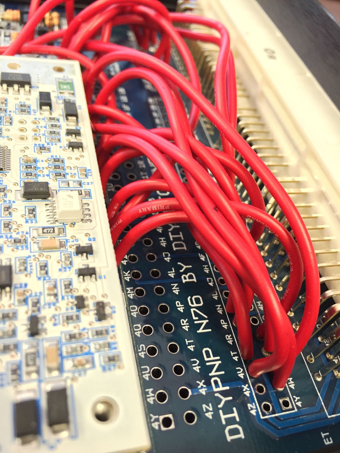
Should I make sure that the yellow wire is jumpered to 4N on the DIYPNP? That is the pin for the o2 sensor.
Reply
0
0

Thread
Thread Starter
Forum
Replies
Last Post
adamiata
ECUs and Tuning
4
May 12, 2014 12:33 PM
chitty chitty bang bang
MEGAsquirt
3
Dec 2, 2013 02:48 PM


