
Tach Adapter for NA w/ Stock ECU and COP


Thread Starter
Senior Member
iTrader: (3)
Joined: Dec 2011
Posts: 592
Total Cats: 47
From: Tucson, Az
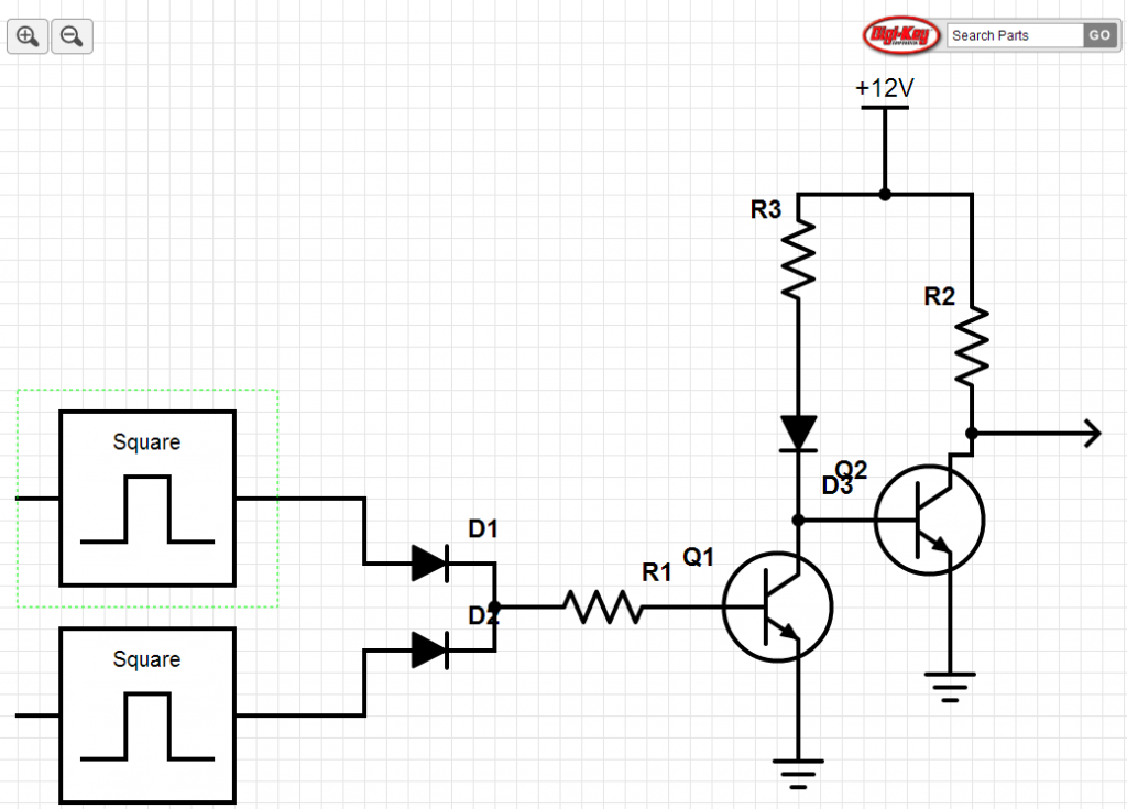
So I'm going with a DIY of Fab9's COP setup using Denso pencil coils. They have no tachometer output, and neither does the Bosch igniter used in this setup. I read Joe's post here about using the coil trigger lines to generate a tach signal using two NPN transistors as in the spark inversing circuit here.
Does this look right? I'll be using three 1N4001 diodes, and three 1k resistors, as well as two 2N3904 transistors. The square wave inputs are the coil triggers, and the output will go to the tach. I want to use the stock ECU's tach 12v (Black/White) as the 12v source. I would tap into the coil triggers (my FSM disagrees with what most stuff on here says and says I have 90-93 wire colors) at the Brown/Yellow and Brown wires. It makes sense in my head, will it also make sense in reality?
Does this look right? I'll be using three 1N4001 diodes, and three 1k resistors, as well as two 2N3904 transistors. The square wave inputs are the coil triggers, and the output will go to the tach. I want to use the stock ECU's tach 12v (Black/White) as the 12v source. I would tap into the coil triggers (my FSM disagrees with what most stuff on here says and says I have 90-93 wire colors) at the Brown/Yellow and Brown wires. It makes sense in my head, will it also make sense in reality?
Last edited by TheScaryOne; May 10, 2014 at 02:58 AM. Reason: Clearer title
Reply
 0
0

0


Junior Member
Joined: Sep 2011
Posts: 433
Total Cats: 17
From: finger lakes NY
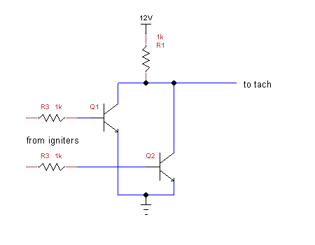
I don't think you need Q2 and R2 for a tach circuit. Polarity doesn't really matter does it? It seems like you're just counting pulses/second.
I don't think you need D3 either. The MS mods show an LED there, but that's just because it's already there as far as I can tell.
Finally, D1 and D2 might work to prevent crosstalk between the igniters, I don't know.
This is what I would build:
I don't think you need D3 either. The MS mods show an LED there, but that's just because it's already there as far as I can tell.
Finally, D1 and D2 might work to prevent crosstalk between the igniters, I don't know.
This is what I would build:
Last edited by DaveC; May 10, 2014 at 11:27 AM. Reason: forgot the base resistors
Reply
0
0
Thread Starter
Senior Member
iTrader: (3)
Joined: Dec 2011
Posts: 592
Total Cats: 47
From: Tucson, Az
I was wondering that about polarity myself. I couldn't really find a good post about what the tach signal is looking for or what the stock coils feed. I've got a friend with a scope, I think I might take a look at it to see whether or not I can just use the B/W tach wire without splicing and pull it to ground to make the tach work.
Reply
0
0

Thread
Thread Starter
Forum
Replies
Last Post
hi_im_sean
Miata parts for sale/trade
1
Sep 16, 2015 12:45 PM
JacksonRacingEngines
Engine Performance
10
Sep 10, 2015 09:52 AM


