

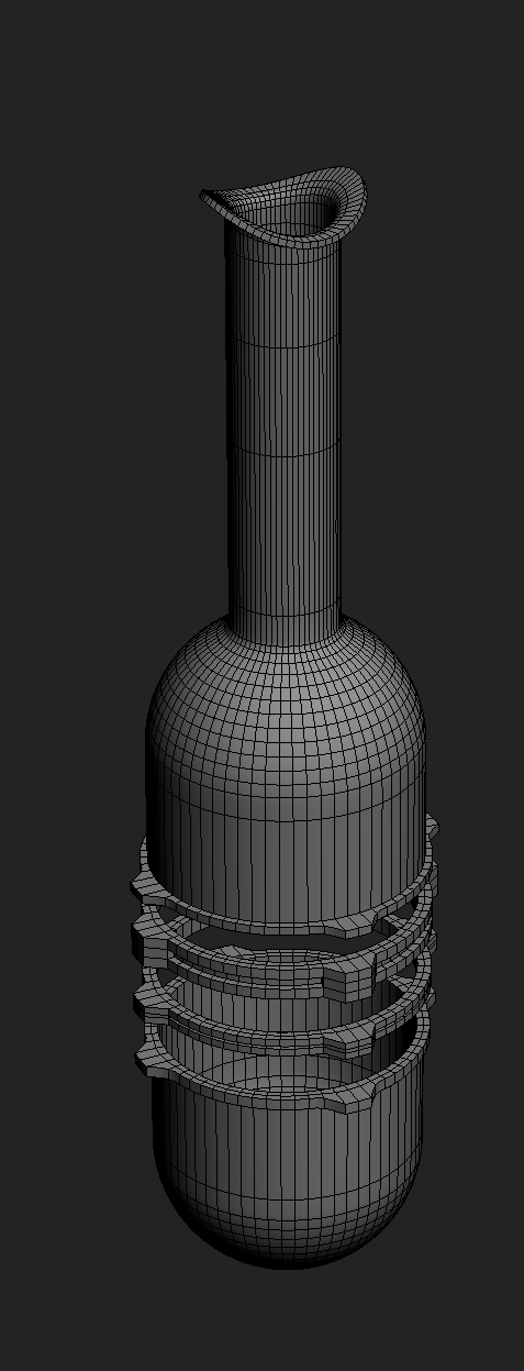
3d printed intake for N/A NA miatas


Junior Member
Joined: Jul 2009
Posts: 422
Total Cats: 45
From: Orange County, CA
Reply
 0
0

0

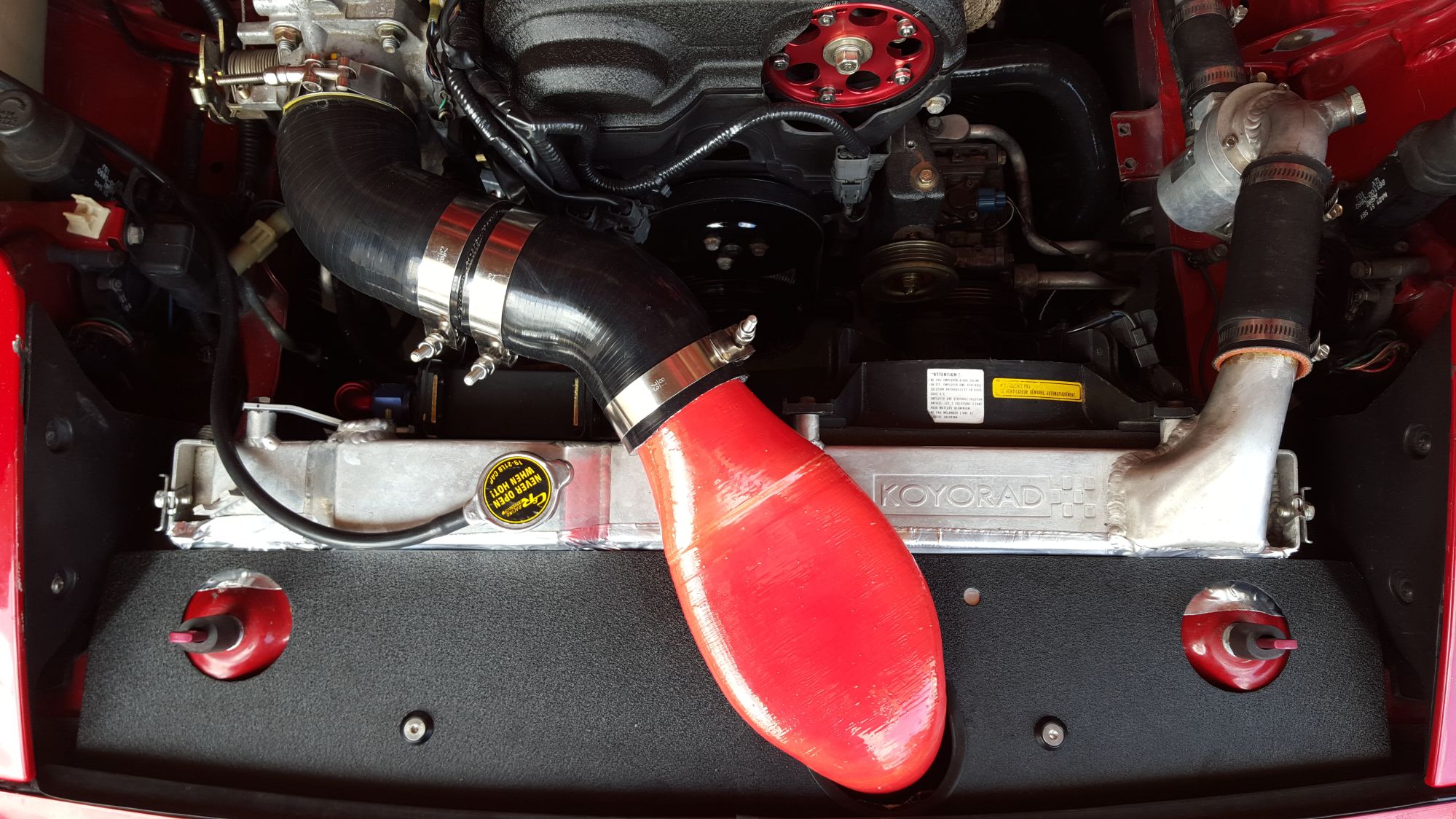
Finished my intake installation today. Ended up using a 60 degree that I had to add 15 degrees by cutting the end at a slant, a 2.75 stainless coupler and a 45 degree elbow. I don't have a hood latch obviously. Total lenght is 20". I think it will make a little more power than using a 90 degree elbow. I also had to cut the hood a bit to make it fit.

Reply
0
0

Thread Starter
Joined: Jul 2012
Posts: 792
Total Cats: 143
From: durham NC
Looks great. I mocked up that location this weekend while I had the hood latch off.
At some point I am going to be doing multiple days of dyno testing with a bunch of parts and I will a/b that location with the stock hole.
Someone on miata.net had their printed plastic duct fail. It warped and shrank until it was a really narrow opening. I haven't tested aluminum radiator surface temps, it might be a good idea to throw a small piece of something like header wrap between the duct and the top of the radiator to force a gap.
Reply
0
0
Thread Starter
Joined: Jul 2012
Posts: 792
Total Cats: 143
From: durham NC
If you already have an air gap a small piece of heat reflective foil is good added insurance. If you don't have any, I can cut off a scrap piece and throw it in an envelope for you. The pictures of that guy's warped intake freaked me out. I suspect that his printer used PLA instead of ABS but either way, ~200F radiator surface is pushing the limits of ABS plastic.
Reply
0
0
Thread Starter
Joined: Jul 2012
Posts: 792
Total Cats: 143
From: durham NC
Audio recording of my helmholtz resonator:
https://i.imgur.com/PqzYNpL.png
This is within 5hz of the frequency the calculator predicted. I think I am going to tweak it slightly to put the center at 3700rpm
https://i.imgur.com/PqzYNpL.png
This is within 5hz of the frequency the calculator predicted. I think I am going to tweak it slightly to put the center at 3700rpm
Reply
0
0

Thread Starter
Joined: Jul 2012
Posts: 792
Total Cats: 143
From: durham NC
I am hoping by the summer. I just got 12 cartridge heaters and a screw in thermocouple from mcmaster carr. I need to take measurements off of them and then finish the cad work on the molds. Once the molds are done, I should be able to make them a lot faster than with the silicone molds I was using before. I am going to switch to prepreg, and the self heating aluminum molds can be run hotter than the oven I built, the layup time with prepreg is short, and the cure time with pre-preg at about 250F is much faster as well.
Reply
0
0

I was originally on the list for one of these, then life happened and I needed to change direction with my modifications.
Will you have a kit available for NAs that still need to use the MAF? I was originally building for CSP, but I'll be forced to content myself with STS for now, and the MAF must be retained.
ETA: Just looked through the thread again, saw you had a NA with stock ECU early on in development. However, still interested to know if you plan on having a kit available or if I'd need to piece things together.
Reply
0
0

Thread Starter
Joined: Jul 2012
Posts: 792
Total Cats: 143
From: durham NC
I was originally on the list for one of these, then life happened and I needed to change direction with my modifications.
Will you have a kit available for NAs that still need to use the MAF? I was originally building for CSP, but I'll be forced to content myself with STS for now, and the MAF must be retained.
ETA: Just looked through the thread again, saw you had a NA with stock ECU early on in development. However, still interested to know if you plan on having a kit available or if I'd need to piece things together.
Will you have a kit available for NAs that still need to use the MAF? I was originally building for CSP, but I'll be forced to content myself with STS for now, and the MAF must be retained.
ETA: Just looked through the thread again, saw you had a NA with stock ECU early on in development. However, still interested to know if you plan on having a kit available or if I'd need to piece things together.
Reply
0
0
Reply
0
0
Thread Starter
Joined: Jul 2012
Posts: 792
Total Cats: 143
From: durham NC
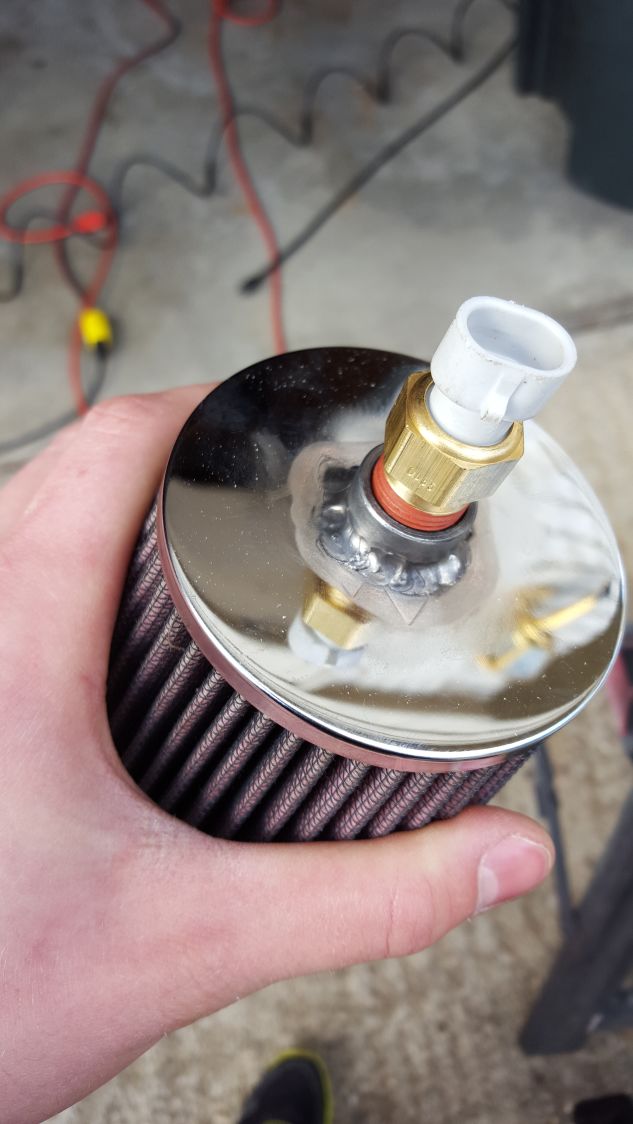
There isn't any room just after the intake filter in the pipe. The air filter flange fits almost directly against the bottom of the radiator support bar.
In practice, that IAT location has been great. Way less issues with heat soak than when I had it in the engine bay. The temps it reads are comparable to what I measured sticking a thermocouple in open air nearby.
In practice, that IAT location has been great. Way less issues with heat soak than when I had it in the engine bay. The temps it reads are comparable to what I measured sticking a thermocouple in open air nearby.
Reply
0
0
I had issues at idle where the main inlet was my bov since it leaked a little at idle. The ait had no airflow, sine it was further doenstream, and the readings weren't representativre.
Reply
0
0

Joined: Apr 2014
Posts: 18,643
Total Cats: 1,870
From: Beaverton, USA
Reply
1
1


