
The definitive "How do I catch can?" thread.
 05-15-2014, 10:28 AM
#41
Senior Member

Join Date: Feb 2009
Location: Philadelphia
Posts: 916
Total Cats: 70
I can deal with the smells, girlfriend can't, but she doesn't really like riding in it anyway. I keep telling her the faster I go the less you can smell but 
When you open the oil cap does yours smell like fuel a bit? I can't go smell mine now cause I'm sick but just wondering.
When you open the oil cap does yours smell like fuel a bit? I can't go smell mine now cause I'm sick but just wondering.

Reply
 0
0

0

 12-17-2014, 06:16 PM
#47

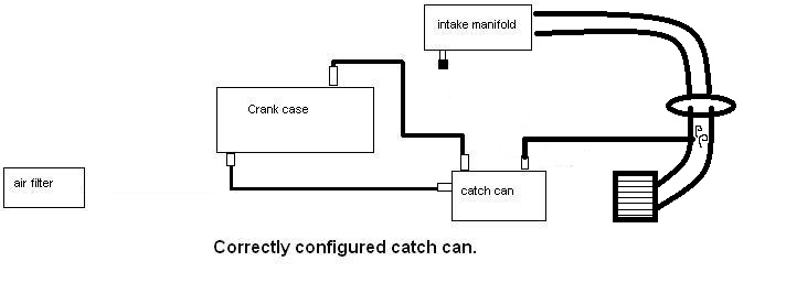
Chiburbian has the best diagram so far.
One BIG thing I see missing in all of this discussion is the physical location of any catch-can away from heat as far as possible i.e. behind the headlight or up in the cowl area on the other side of the divider. This is because the cooler the environment, the more condensing it will be doing and less vapors making their way back into the intake/vacuum source. You also don't want to have the can running VTA- always keep a closed-loop system.
Having vacuum on the crankcase also makes a lot of seals very happy.
Reply
0
0
12-17-2014, 10:36 PM
#48
Senior Member

iTrader: (2)

Join Date: Oct 2013
Location: Goleta, Southern California
Posts: 520
Total Cats: 27
I've researched this for the last few months and here is what I've come up with. My car is only mildly boosted so all I need is a mild solution. I do not want to vent to atmosphere because I hug trees.
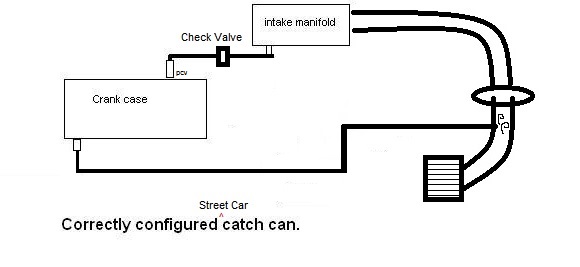
1) I installed a heavy duty check valve coming out of the intake manifold, which normally goes to PCV valve. This is because even my GTX valve leaked boost into the crankcase. Now under boost there is zero issues with boost getting in the crank case.
2) Added a separator/can in between the check valve above and the PCV valve. Because even a stock engine will suck plenty of oil though PCV into the intake. At least now I can catch most of it and drain it.
That sums it up for PCV side of things. Since under boost that side of things does nothing for for venting CC under boost I moved to inlet side of things (well in an naturally aspirated engine). Which becomes the only outlet under boost. I figured this side of things needed some attention because it was never designed in our NA engines to be the only vent for CC.
3) Removed the valve cover and the plates on the underside sealing the PCV and "inlet" chambers in the VC. I only resealed the PCV plate for good measure. On the "inlet" side I opened up the small ~1/4" hole between the center chamber and the passenger side "inlet" chamber to 3/8", just like others have done on this board.
The purpose here is to allow more flow since it will be doing all the venting under boost.
I also realized that if any oil got from the center chamber to the "inlet" chamber it could not get back into the center chamber to drain because the hole does not go to the floor of the "inlet" chamber.
4) So I ground out the 3/8" hole toward the chamber floor a bit to allow the oil to drain out of the "inlet" chamber back to the center chamber sooner. I couldn't make the hole touch the floor of the "inlet" chamber because is would mean the plate would no longer seal. So now the oil will only have to be ~1/8" high in the "inlet" chamber before it can drain out. Not ideal, but better than before.
5) Pulled the stock 3/8" "inlet" nipple from the VC. Drilled and taped for a 3/8" NPT to 1/2" hose barb fitting. Again, just opening things up for flow when in boost.
6) Because I really want to keep the oil from getting from the center chamber to the "inlet" chamber, I put cooper wool in the center chamber around the drain area. Not a lot. Just enough so that all blowby must pass though it to enter the "inlet" chamber. I kept the wool away from the 3/8" transfer hole because I don't want any condensed oil being sucked into the "inlet" chamber. Next I resealed the plates to the valve cover.
Opening up those ports on the "inlet" side should significantly improve flow of blowby during boost.
7) Installed a second catch can/separator between the new 1/2" hose barb on the VC and the pre-turbo (or supercharger) "inlet" hose. This can catches any oil that makes it out of the "inlet" chamber in the valve cover.
8) Lastly I wrinkle painted the valve cover black. Because everyone knows this is best for a well constructed PCV system.
Overly complicated because I hug trees? Maybe. Does everything the stock system does only better? Yes.
Reply
0
0


 12-18-2014, 09:37 AM
#54
I'll work on the scrubbies.
My main point was wither or not it was acceptable to plumb the "breather" line into the intake path rather than have a standard "filter".
Reply
0
0
12-18-2014, 09:40 AM
#55
Thats how mine is, and I havent had a drop of oil in the intake tube or turbo since I stopped trying to use the block vent I drill and put the copper scrubbies in the valve cover. And by not a drop I mean after i cleaned the tube out brake klean from getting drenched by the messed up setup the intake hasnt even formed an oily film on the walls like you'd expect. Thats with a -10an fitting on the valve cover and a -12 on the intake tube.
Reply
0
0
12-20-2014, 10:30 AM
#57
Retired Mech Design Engr
iTrader: (3)
Join Date: Jan 2013
Location: Seneca, SC
Posts: 5,009
Total Cats: 857
Thats how mine is, and I havent had a drop of oil in the intake tube or turbo since I stopped trying to use the block vent I drill and put the copper scrubbies in the valve cover. And by not a drop I mean after i cleaned the tube out brake klean from getting drenched by the messed up setup the intake hasnt even formed an oily film on the walls like you'd expect. Thats with a -10an fitting on the valve cover and a -12 on the intake tube.
Reply
0
0


 12-20-2014, 05:44 PM
#60
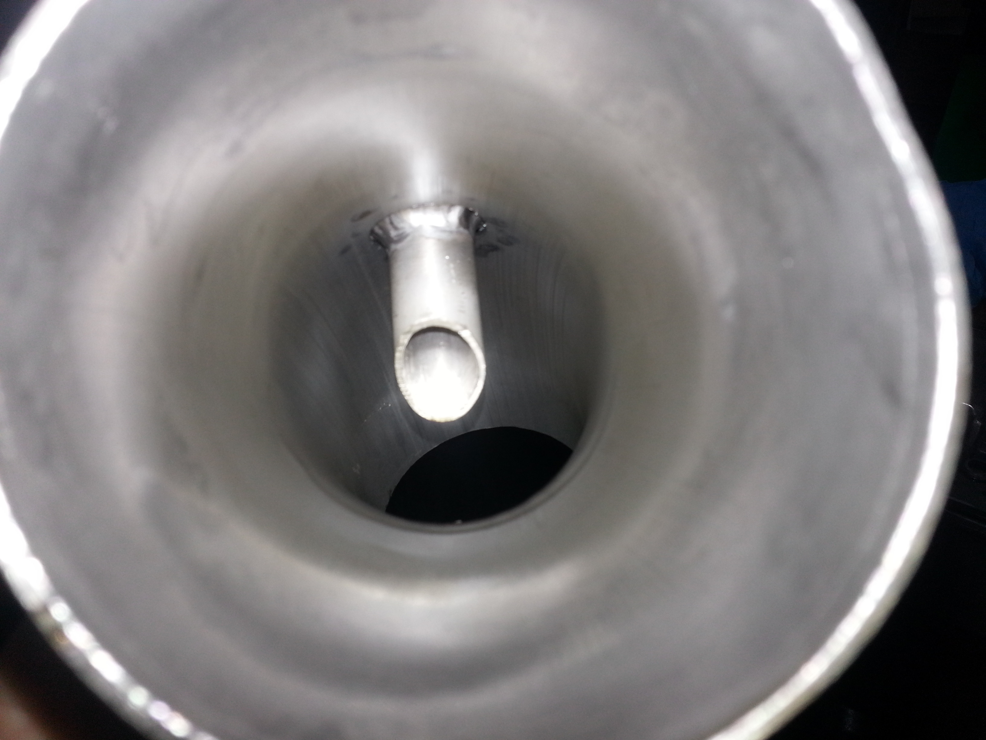
Intake slashcut, looking at it from the air filter side, and after taking this picture I realized it got spun 180 from the direction it should have been... ooops.
Routing
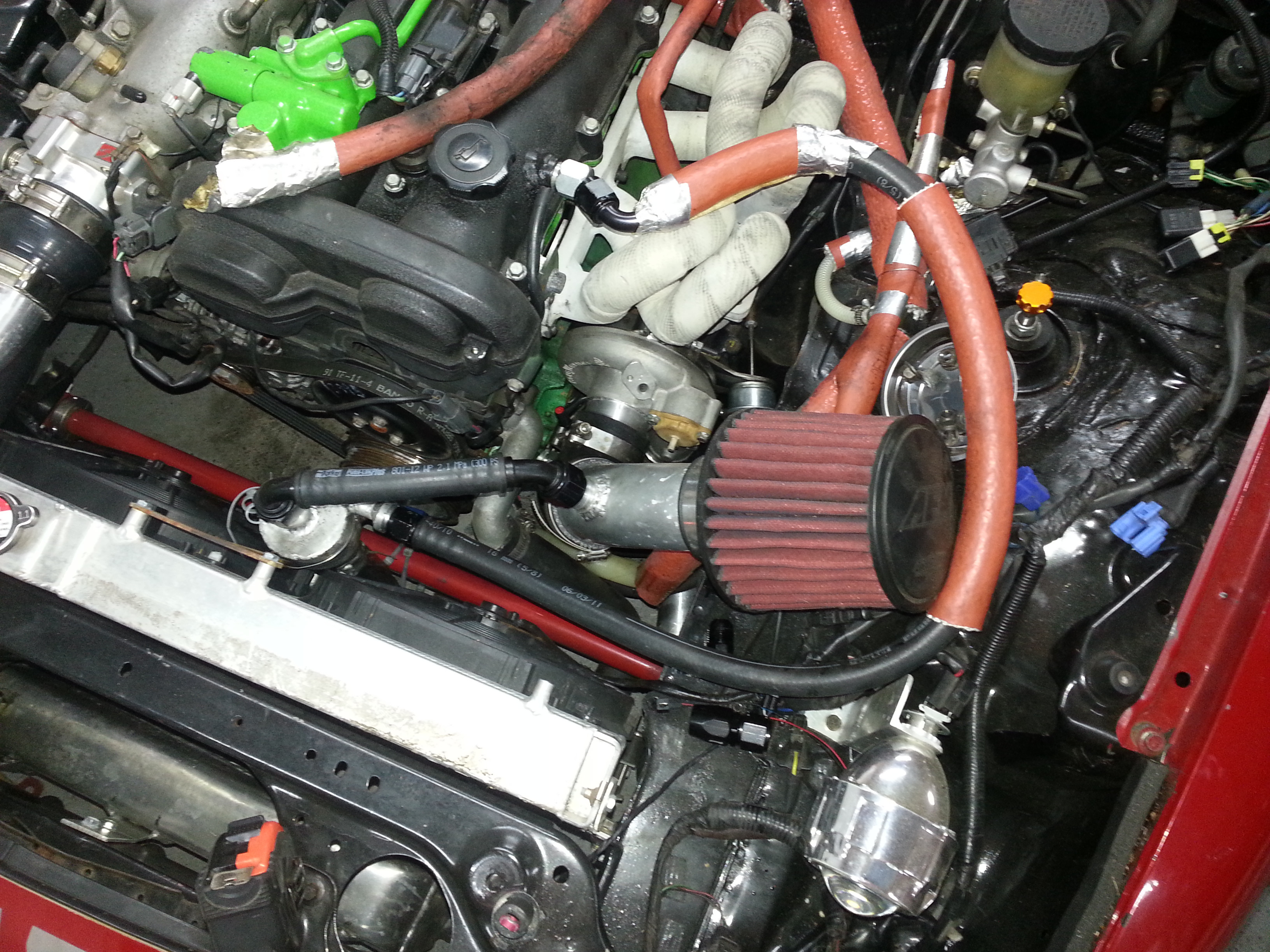
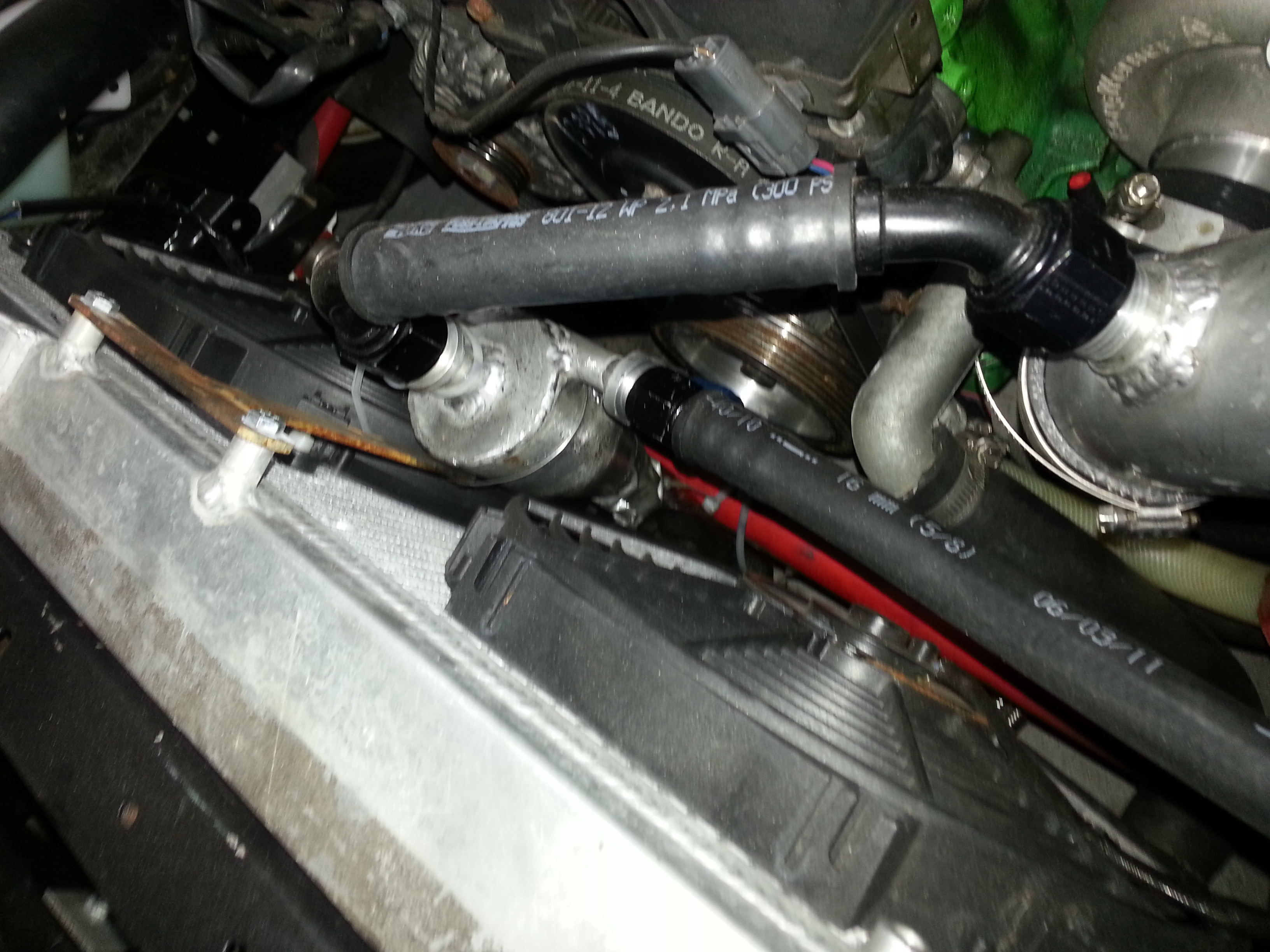
You probably saw the inner design of the catch can itself in my build thread and I dont feel like searching back to re-post that stuff. I need to come up with a more elegant drain design though. Right now it drains from the catch can goes into a crystal geiser water bottle taped to the swaybar.
Routing
You probably saw the inner design of the catch can itself in my build thread and I dont feel like searching back to re-post that stuff. I need to come up with a more elegant drain design though. Right now it drains from the catch can goes into a crystal geiser water bottle taped to the swaybar.
Reply
0
0


