
How to wire VVT engine on an NA

 04-08-2013, 10:37 AM
#45

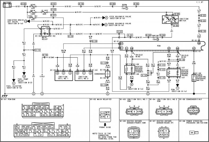
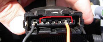
It was very hard to find the pinout pin out wiring of the 01 VVT 01+ ingestion spark coils (I added all those words so hopefully this post will come up on google when some other poor sucker is trying to figure it out) From top to bottom it is trigger, ground, power. However, if you dont get spark after pinning the connectors, de-pin the connector and crush the pins down a bit then put it back together. I noticed that the pins on the coil pack side are undersized and sometimes wont make contact with the pins in the harness side connector if you use pins form either bmotorsports or eastern beaver that are recommended for the connector. It is possible that a slightly different pin might need to be spec'ed to work with these coils in this connector.

Reply
 1
1

1
04-08-2013, 10:47 AM
#46
Tour de Franzia

iTrader: (6)
Join Date: Jun 2006
Location: Republic of Dallas
Posts: 29,085
Total Cats: 375
It was very hard to find the pinout pin out wiring of the 01 VVT 01+ ingestion spark coils (I added all those words so hopefully this post will come up on google when some other poor sucker is trying to figure it out) From top to bottom it is trigger, ground, power. However, if you dont get spark after pinning the connectors, de-pin the connector and crush the pins down a bit then put it back together. I noticed that the pins on the coil pack side are undersized and sometimes wont make contact with the pins in the harness side connector if you use pins form either bmotorsports or eastern beaver that are recommended for the connector. It is possible that a slightly different pin might need to be spec'ed to work with these coils in this connector.
Reply
0
0
04-08-2013, 10:50 AM
#47
That weird, mazdamaki doesnt even have the 01+ wiring that I cant find. I know that if you do an 94-95 with VVT coils you need brown on the front coil (2/3) top and brown/yellow (1/4) on the rear coil top, black in the middle for both, and light blue on the bottom for both.
Reply
0
0
 04-08-2013, 12:18 PM
#56
Boost Czar

iTrader: (62)
Join Date: May 2005
Location: Chantilly, VA
Posts: 79,499
Total Cats: 4,080
connector pictures with a double outline are the male, and a single outline are female. and are almost always from the harness side (notice the main relay in the above mentions it's the terminal side).
So it should be looked at, like you unplug the connector, then look into it like this:
i could be wrong. I always just double check.
So it should be looked at, like you unplug the connector, then look into it like this:
i could be wrong. I always just double check.
Last edited by Braineack; 04-08-2013 at 12:37 PM.
Reply
0
0
 )
)


