
KL-DE powered sand-rail
 07-13-2010, 07:50 AM
#61

Love the gas cap, you should get a nice o ring to seal it and keep it that way. It would be a nice 'conversation starter' at the gas pumps.  I assume its got a weighted tube with the pickup filter on the end?
Very creative low buck solutions! Keep it going, I'm still waiting for donuts/ exh sound vid.
I assume its got a weighted tube with the pickup filter on the end?Very creative low buck solutions! Keep it going, I'm still waiting for donuts/ exh sound vid.

Reply
 0
0

0
07-13-2010, 08:31 AM
#62
Senior Member
Thread Starter
iTrader: (1)

Join Date: Aug 2006
Location: Illinois
Posts: 1,011
Total Cats: 7
Love the gas cap, you should get a nice o ring to seal it and keep it that way. It would be a nice 'conversation starter' at the gas pumps. I assume its got a weighted tube with the pickup filter on the end?
Very creative low buck solutions! Keep it going, I'm still waiting for donuts/ exh sound vid.
I assume its got a weighted tube with the pickup filter on the end?Very creative low buck solutions! Keep it going, I'm still waiting for donuts/ exh sound vid.
The exhaust isn't as loud as you may think. The GSX-R mufflers do a damn good job of keeping it quiet. It just sounds like a car but at higher RPM you can make out some rapping. Think fart-canned Civic burried under 50 feet of hay. The bolts on the end caps are stuck but I'd like to drill them out and replace them so I can remove the baffles and try that out but still be able to put them back in. That's been the nice thing about this toy. I can do whateverthemuffins I want to it.
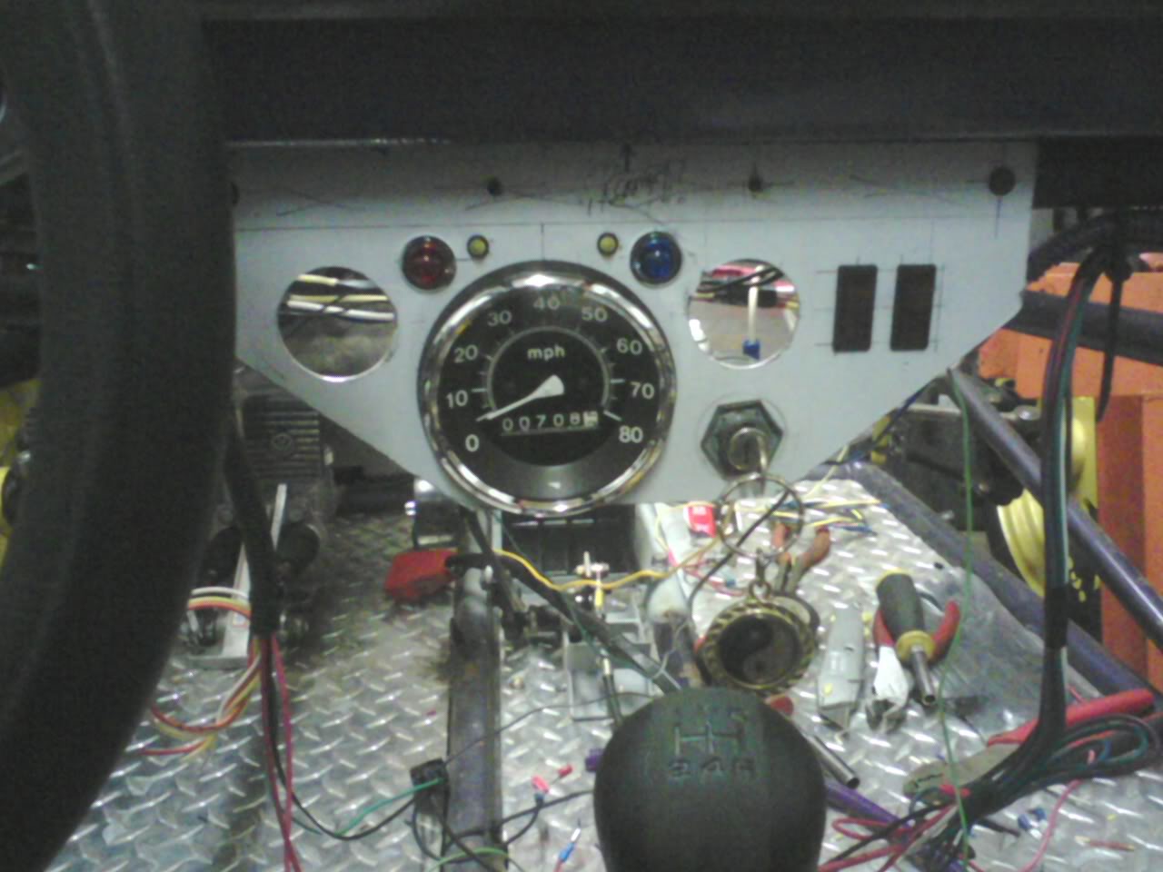
I made a new instrument cluster tonight. The speedo is easier to see and has 2 small gauges on either side for oil and temp. There's also a CEL and a high-beam indicator lamp. Two lighted red rocker switches for the headlights and offroad lights and the ignition switch is also on it. I have to rewire it but that's all part of the fun.
The vehicle will have 7 fuses and 5 relays.
They are:
1 - Coil/dist (relay) 10a
2 - Injector/solonoid (relay) 10a
3 - Fuel pump and starter (starter relay has neutral interlock) (relay x2) 15a
4 - Rad. fan (relay) 20a
5 - Headlights/running lights 20a
6 - Horn/Brake light/Turn signals 15a
7 - Offroad lights (4x55w) 20a
Once the relays are wired, I'll tape them together and pot the terminals in a brick. If a relay fails I can yank it and pop in a new one without worrying about which wire went where.
Reply
0
0
07-14-2010, 10:50 AM
#63
Senior Member
Thread Starter
iTrader: (1)
Join Date: Aug 2006
Location: Illinois
Posts: 1,011
Total Cats: 7
Here's what I had in mind for the instrument cluster. Speedo in the middle with temp and oil pressure next to it. Red light is CEL. Blue light is high-beam. The two small yellow LEDs are the turn signal indicators. The two switches are headlight/running lights on the left and offroad lights on the right. The headlights and offroad lights have power when the vehicle is off. Turn only has power with the key on. The high/low and turn signal switches are both center-off SPDT and will be located to the left of the steering wheel. The center-off on the high/low switch allows me to turn on the light switch (left cluster switch) for parking lights only. I have to pull the offroad light wiring out and replace it because someone only wired it in 16ga. There's 4 55w bulbs to light and the wire gets toasty.
I don't need a tach since the ECU has a 7500 redline which is safe enough. If I do add one later I'll use a micro tach and locate it near the steering wheel. I did pull a tach signal wire when I did the vehicle harness just in case.
I don't need a tach since the ECU has a 7500 redline which is safe enough. If I do add one later I'll use a micro tach and locate it near the steering wheel. I did pull a tach signal wire when I did the vehicle harness just in case.
Reply
0
0
 .
07-14-2010, 07:59 PM
.
07-14-2010, 07:59 PM
#65
Senior Member
Thread Starter
iTrader: (1)
Join Date: Aug 2006
Location: Illinois
Posts: 1,011
Total Cats: 7
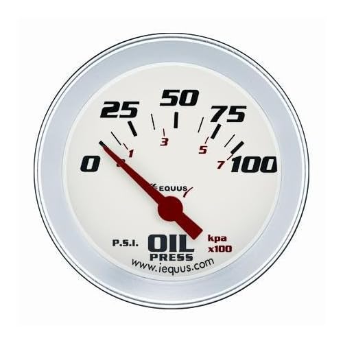
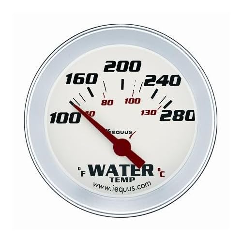
 Apperently Sun and Autometer are still living in the '50s when cars had dash room for half a dozen 2.5" mechanical gauges.
According to calculations, the engine is 18ft-lbs of torque away from a wheelie. Bump that clutch too much and it's going up though. lol
Reply
0
0
 07-15-2010, 05:39 AM
#70
Senior Member
Thread Starter
iTrader: (1)
Join Date: Aug 2006
Location: Illinois
Posts: 1,011
Total Cats: 7
EDIT found some. Equus makes 1.5" electronic but it only comes in white face! -doh- Oh well. It'll have to do.
Last edited by lazzer408; 07-15-2010 at 07:39 AM.
Reply
0
0
07-16-2010, 12:44 AM
#71
Junior Member

Join Date: Jul 2008
Posts: 113
Total Cats: 1
I very much enjoyed reading this thread and think that not only is this going to be ridiculously fast, but with the correct suspension geometry could handle really really super amazingly awesome (as if anything weighing 1000lbs isnt going to handle decently as is) assuming you aren't planning on dual sporting in the sand...
Reply
0
0
07-16-2010, 02:44 AM
#72
Senior Member
Thread Starter
iTrader: (1)
Join Date: Aug 2006
Location: Illinois
Posts: 1,011
Total Cats: 7
My friend left his cam and cable here at the shop so I snapped a quick vid. There's a 18" flex pipe off the manifolds but nothing after that so it's kinda loud. Pardon the mess.
Working with video on a computer is a F#^%$ing pain in the A$$
...one moment
Ok here we go. The two red lights are ALT(left) and CEL(right)
http://www.youtube.com/watch?v=_sv6Xwgm9RA
Working with video on a computer is a F#^%$ing pain in the A$$
...one moment
Ok here we go. The two red lights are ALT(left) and CEL(right)
http://www.youtube.com/watch?v=_sv6Xwgm9RA
Last edited by lazzer408; 07-16-2010 at 03:05 AM.
Reply
0
0


 07-16-2010, 08:00 AM
#75
My wife is going to hate you for renewing my desire to build my own car. I see Lincoln has a mig pack 180 on for $600 with tons of accessories and it's almost my birthday hmm.
What did you use for the turn signals? I'm thinking it's all 626 parts for that considering that's the harness you used but is it?
Does the trans shift properly (grinding free) like that? I've seen a few $500 v6 626's lately but I think another project on the go will lead to being murdered in my sleep.
I can't wait to see this thing going down the road.
Reply
0
0
07-16-2010, 06:17 PM
#76
Senior Member
Thread Starter
iTrader: (1)
Join Date: Aug 2006
Location: Illinois
Posts: 1,011
Total Cats: 7
Pure awesomeness.....
My wife is going to hate you for renewing my desire to build my own car. I see Lincoln has a mig pack 180 on for $600 with tons of accessories and it's almost my birthday hmm.
What did you use for the turn signals? I'm thinking it's all 626 parts for that considering that's the harness you used but is it?
Does the trans shift properly (grinding free) like that? I've seen a few $500 v6 626's lately but I think another project on the go will lead to being murdered in my sleep.
I can't wait to see this thing going down the road.
The only Mazda wiring I used is the engine harness to the ECU from a Ford Probe GT. I used the Probe GT ECU also. I left the ECU connector and the engine connectors alone but everything else was traced out from schematics and manually wired in. I opened the harness to remove any unused wiring and wired in my own power, grounds, and signals to make it run. It took alot of time but worth it in the end. If you mean the turn signal switches? It's just a DPDT with center off toggle for both the turn and the high/low beam. It has to be manually shut off after a turn.
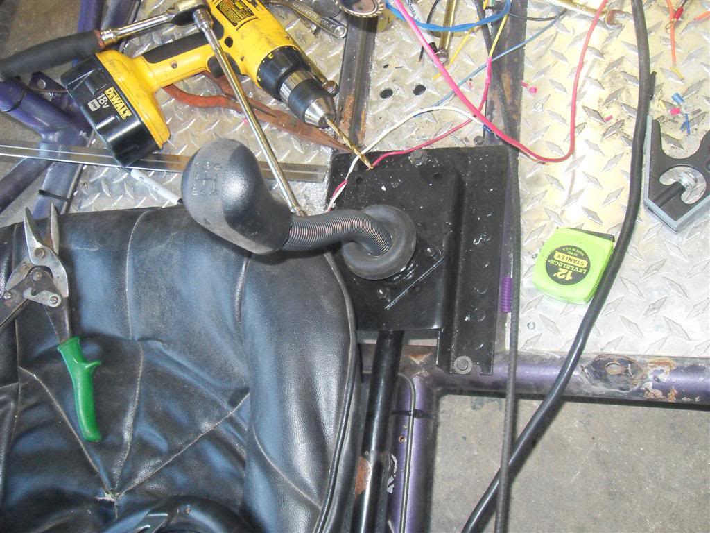
The trans shifts flawlessly. It feels just like stock. I cut about 1" off the shifter handle itself to lower the **** but other then that it's just a Protege shifter. It was very easy to modify into a universal shifter.
Reply
0
0
07-16-2010, 08:17 PM
#77
Senior Member
Thread Starter
iTrader: (1)
Join Date: Aug 2006
Location: Illinois
Posts: 1,011
Total Cats: 7
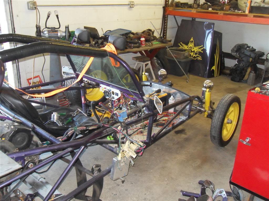
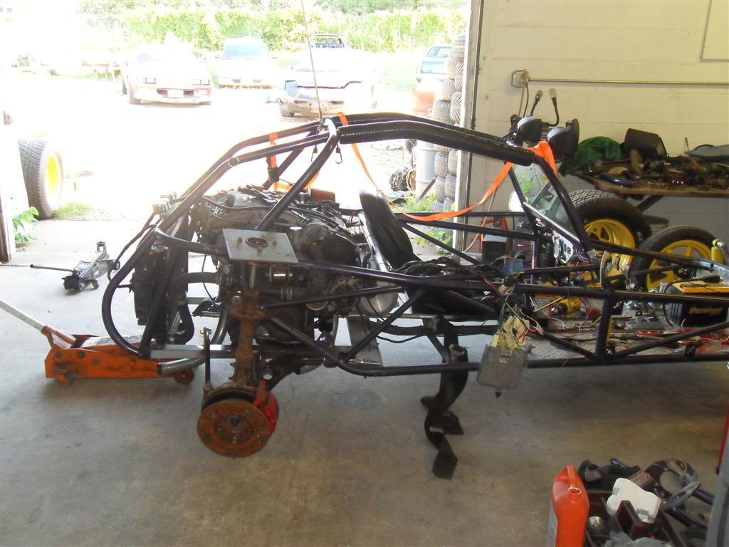
Here's a few more pictures and a video of the shifter movement.
Shifter video: http://www.youtube.com/watch?v=isC28BJ51P8
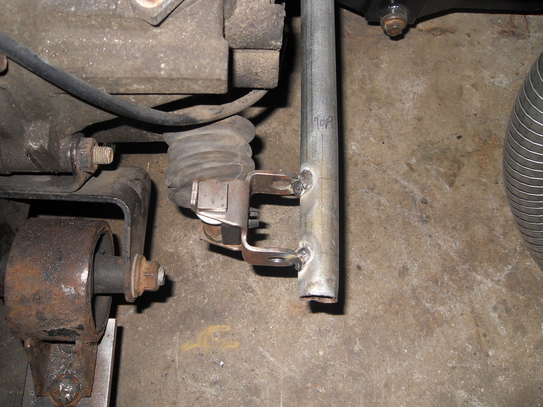
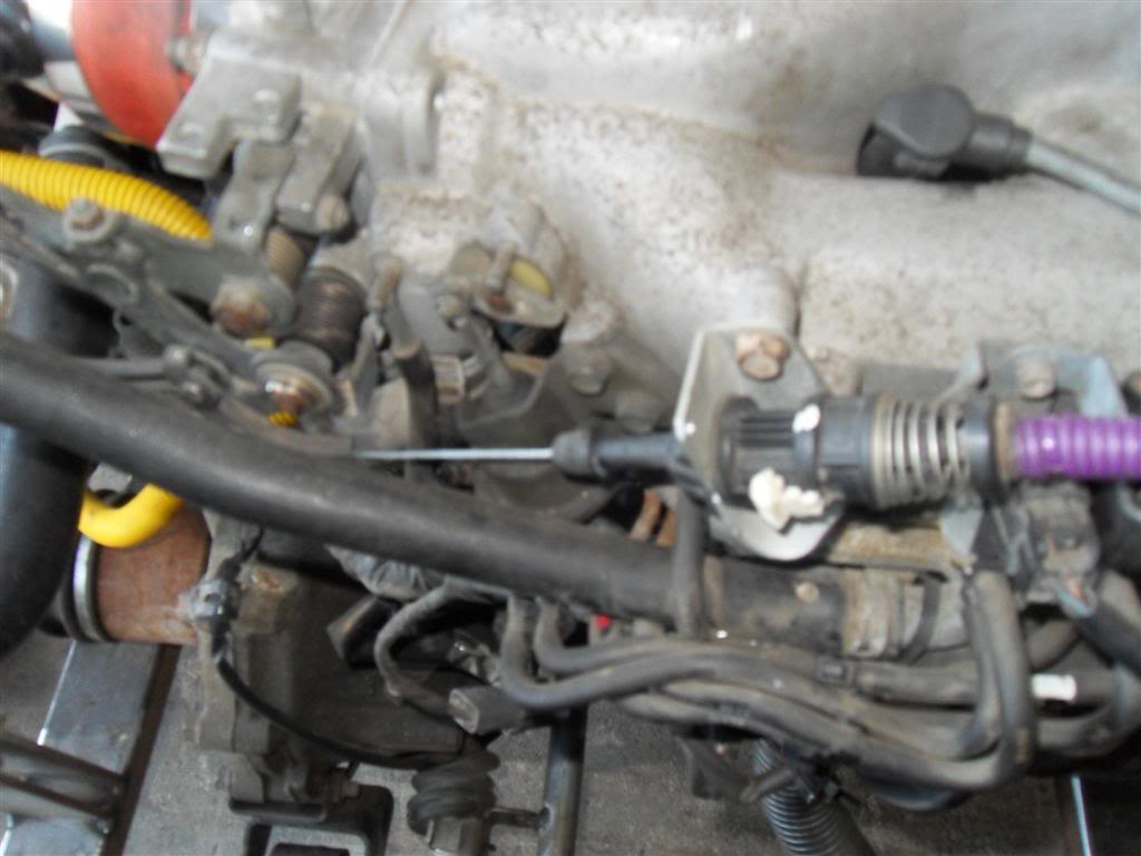
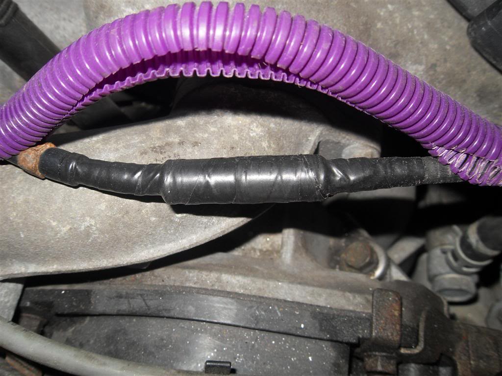
One of the pictures is the throttle cable. What I did was cut the 626 cable sheath and threw away the cable. I then took a 3/8" bolt and cut off the head and the threads so I had a solid rod. I bored one end 1/4" for the Mazda sheath and 5/16" into the other end for the sandrail's sheath leaving 1/4" between the two holes inside the middle of the bolt. I then drilled through it 1/8" to allow the cable to pass. Each cable goes into the ends of the bolt and taped up. I bought 1/16" cable from Home Depot to use as the new throttle cable. For the throttle body connection I used a 6mm bolt and drilled a 1/16" hole through it for the cable then set it with a punch. It looks like a typical throttle end and holds tight.
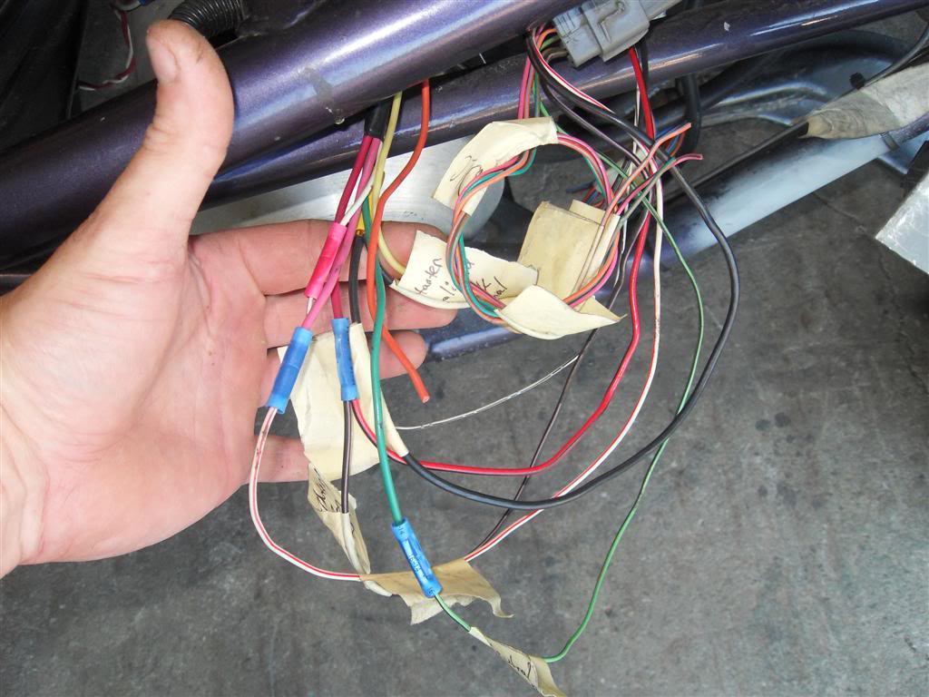
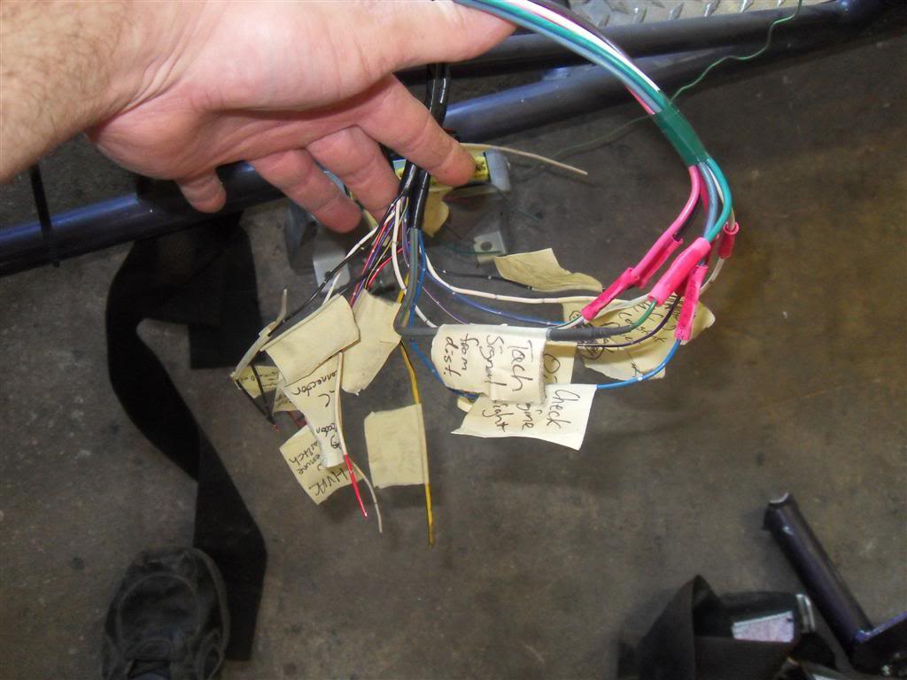
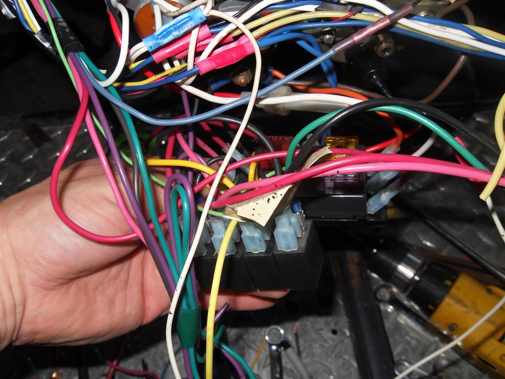
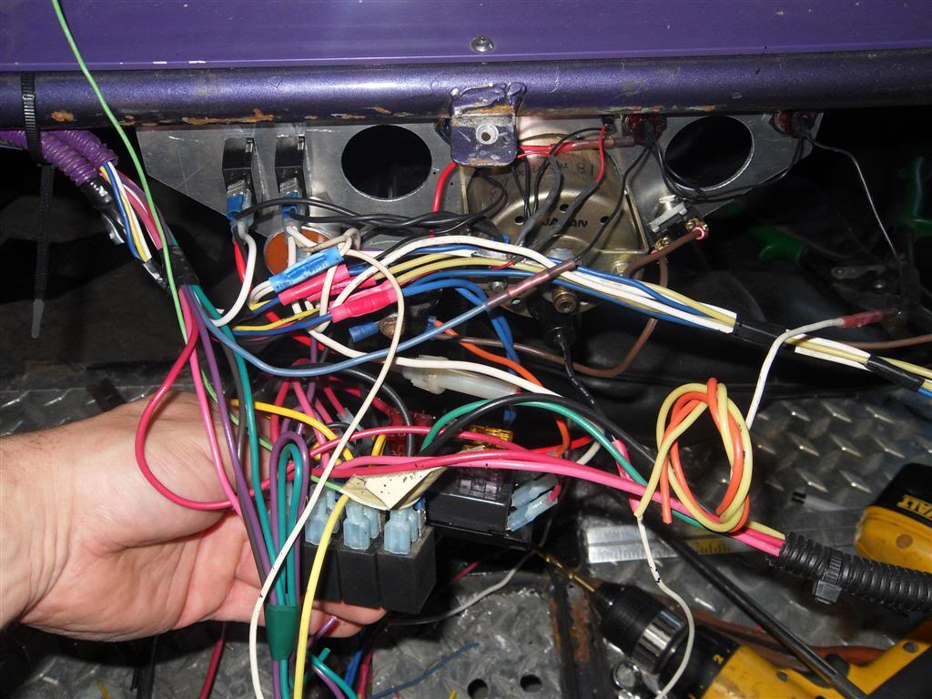
There's some pics of the wiring harness's flying ends. I tagged them all as to their functions and ran my harness in the frame rails up to the cluster where the power distribution and relays are. I know it looks like a mess right now but it's all getting tucked away into a box behind the passenger's seat where the ECU will be located.
The 4 relays are:
-Ignition power (high side signaled from ign switch)
-Injection/solonoid power (high side signaled from ign switch)
-Fuel pump power (low side switched by ECU)
-Starter interlock (high side signaled from ign switch, low side switched by neutral switch)
The 6 fuses are:
-Ignition 10a (to ign relay)
-Injection/solonoids 10a (to inj relay)
-Fuel pump/starter 10a (to fuel pump relay and starter relay)
-Turn/brake/horn/relay power 20a (turn/brake/horn off ign acc position(off while cranking). Relay power off ign terminal of ign switch)
-Head/parking/dash lights 20a
-ECU memory 3a
A 7th 20a inline fuse feeds the offroad lights.
An 8th 20a fuse will be located in the ECU box to provide power to the fan relays which will also be located in the ECU box.
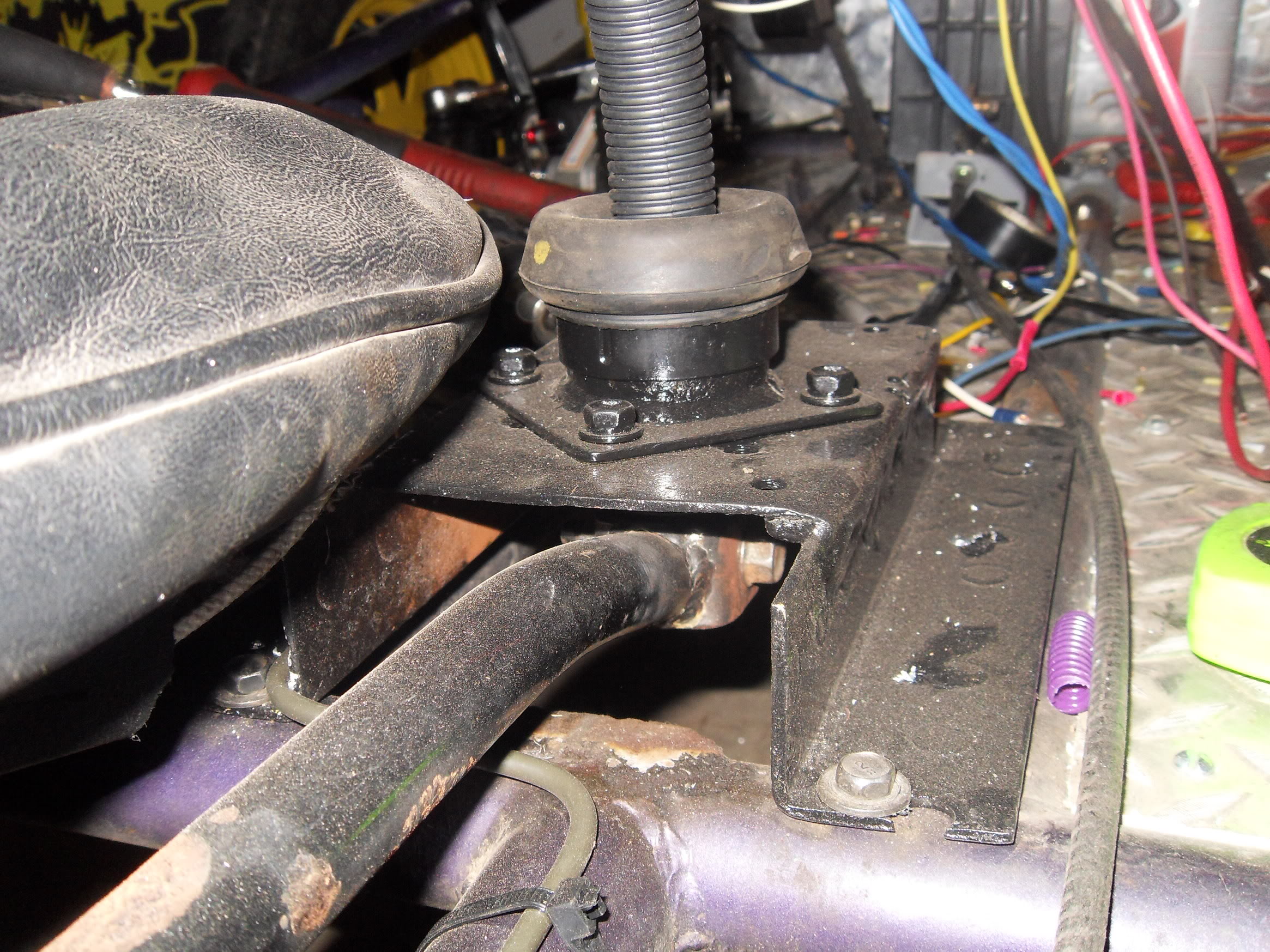
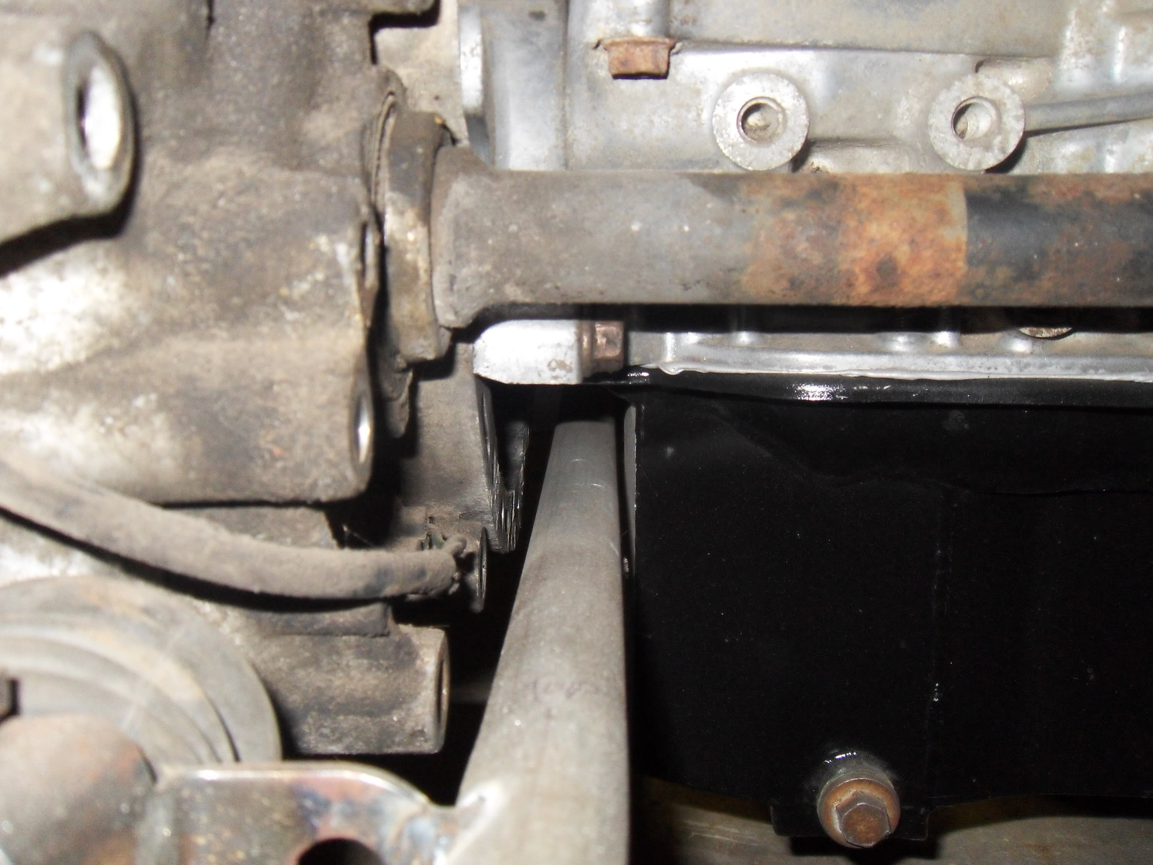
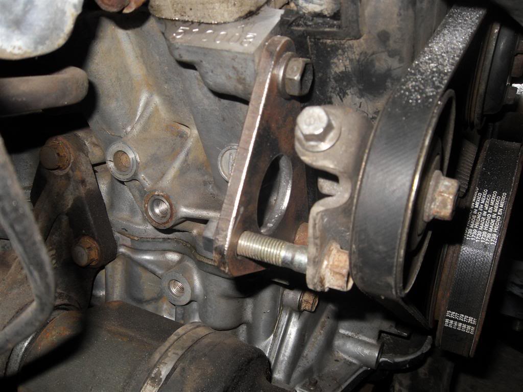
The last pic is the bracket I made to use a Honda Civic's AC tensioner as my water pump belt tensioner. I removed the power steering pump so I needed to add an idler in it's place since that belt drove the water pump. It was easier to do it that way then to relocate the alternator. The alternator has it's own belt and tensioner. I still need to make a couple spacers for it.
Shifter video: http://www.youtube.com/watch?v=isC28BJ51P8
One of the pictures is the throttle cable. What I did was cut the 626 cable sheath and threw away the cable. I then took a 3/8" bolt and cut off the head and the threads so I had a solid rod. I bored one end 1/4" for the Mazda sheath and 5/16" into the other end for the sandrail's sheath leaving 1/4" between the two holes inside the middle of the bolt. I then drilled through it 1/8" to allow the cable to pass. Each cable goes into the ends of the bolt and taped up. I bought 1/16" cable from Home Depot to use as the new throttle cable. For the throttle body connection I used a 6mm bolt and drilled a 1/16" hole through it for the cable then set it with a punch. It looks like a typical throttle end and holds tight.
There's some pics of the wiring harness's flying ends. I tagged them all as to their functions and ran my harness in the frame rails up to the cluster where the power distribution and relays are. I know it looks like a mess right now but it's all getting tucked away into a box behind the passenger's seat where the ECU will be located.
The 4 relays are:
-Ignition power (high side signaled from ign switch)
-Injection/solonoid power (high side signaled from ign switch)
-Fuel pump power (low side switched by ECU)
-Starter interlock (high side signaled from ign switch, low side switched by neutral switch)
The 6 fuses are:
-Ignition 10a (to ign relay)
-Injection/solonoids 10a (to inj relay)
-Fuel pump/starter 10a (to fuel pump relay and starter relay)
-Turn/brake/horn/relay power 20a (turn/brake/horn off ign acc position(off while cranking). Relay power off ign terminal of ign switch)
-Head/parking/dash lights 20a
-ECU memory 3a
A 7th 20a inline fuse feeds the offroad lights.
An 8th 20a fuse will be located in the ECU box to provide power to the fan relays which will also be located in the ECU box.
The last pic is the bracket I made to use a Honda Civic's AC tensioner as my water pump belt tensioner. I removed the power steering pump so I needed to add an idler in it's place since that belt drove the water pump. It was easier to do it that way then to relocate the alternator. The alternator has it's own belt and tensioner. I still need to make a couple spacers for it.
Last edited by lazzer408; 07-17-2010 at 12:29 AM.
Reply
0
0
07-17-2010, 04:44 AM
#78
Senior Member
Thread Starter
iTrader: (1)
Join Date: Aug 2006
Location: Illinois
Posts: 1,011
Total Cats: 7
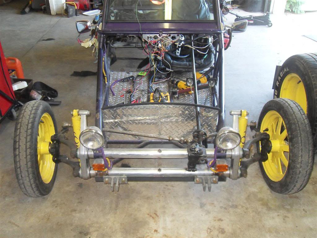
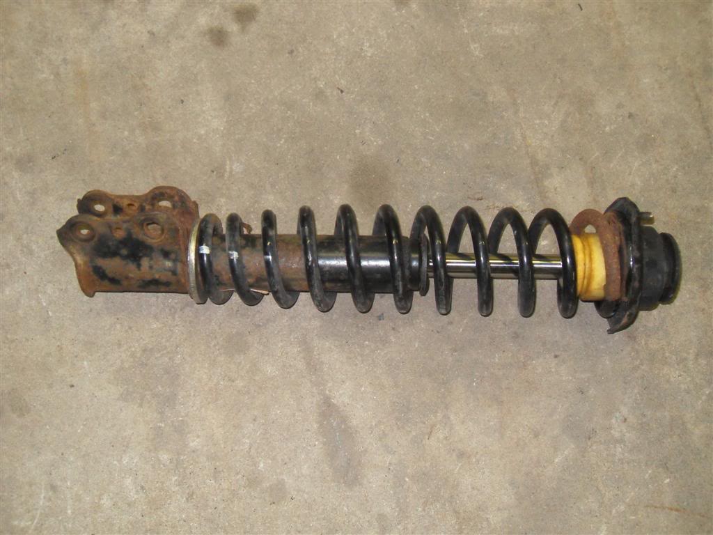
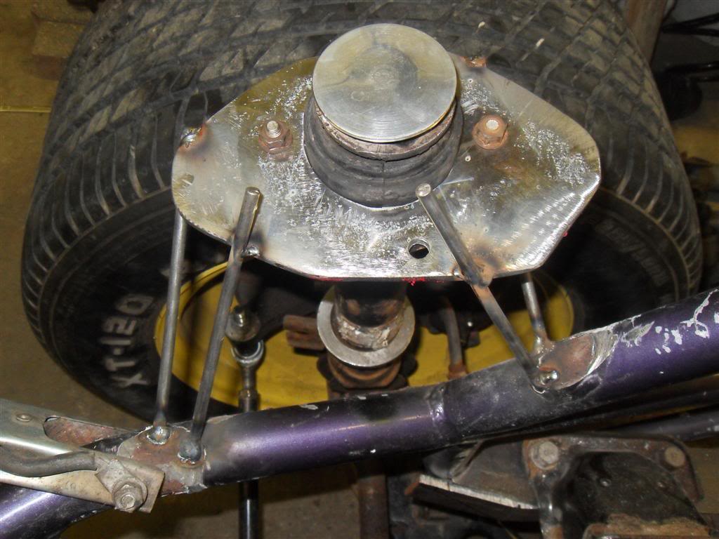
I made some struts tonight. It's the 626 strut with the lower spring hat cut off. I used two different sized hole saws to make a washer to fit over the strut for the bottom of the spring to sit on. I used Civic springs and the Ford EXP hats from the old struts. It has about 5" of travel to the bump stop then about 1" more when it squishes. The frame is 1" from the ground when the struts bottom out.
Reply
0
0
07-17-2010, 06:59 AM
#79
Senior Member
Thread Starter
iTrader: (1)
Join Date: Aug 2006
Location: Illinois
Posts: 1,011
Total Cats: 7
Lets here some color ideas. Give me ideas for the chassis color and accent color. Like purple/yellow.
I'm kinda thinking green/yellow or yellow/green.
Here's pics of yellow and green ones. I really like the green one. I like Kawasaki and Arctic cat too. ^_^


I'm kinda thinking green/yellow or yellow/green.
Here's pics of yellow and green ones. I really like the green one. I like Kawasaki and Arctic cat too. ^_^
Reply
0
0
07-17-2010, 04:00 PM
#80
So no body panels in final assembly?
Do you have access to a piranha (or equivalent) or is all your cutting chop saw? They are a useful machine for small parts and cutting / shaping rod.
Reply
0
0


