

Thread for naturally aspirated manifold design


Thread Starter

Joined: Jul 2012
Posts: 792
Total Cats: 143
From: durham NC
That is 11.5" runners so about 15" to the valve.
The next step is to cast the intake ports. I have some high viscosity brush on silicone coming for that. After that, an expanding foam pour inside the engine bay + 3d scan will give a really good idea of how much space there is to work with and will help determine what can be fit in the engine bay.
I think .25" and .5" spacer plates would be a good way to fine tune runner lengths.
Reply
 0
0

0
Thread Starter
Joined: Jul 2012
Posts: 792
Total Cats: 143
From: durham NC
This assumes a few things. First, no way to include runner taper in the calculation. I fudged it since my runners are a linear interpolation of two shapes- I picked a value in the middle. Second, it needs to be given a speed of sound, which is dependent on the air temp. The suggested number was over 200F, which seems really high, but I am using it since that seems to generate numbers that match practical examples.
Code:
Runner  3rd wave peak	4th wave peak
13.5	6061.607372	4546.205529
13.25	6146.228874	4609.671655
13	6233.246498	4674.934874
12.75	6322.76348	4742.07261
12.5	6414.88907	4811.166803
12.25	6509.73898	4882.304235
12	6607.435867	4955.5769
11.75	6708.109865	5031.082399
11.5	6811.899162	5108.924372
11.25	6918.950633	5189.212975
11	7029.420531	5272.065398
10.75	7143.475251	5357.606438
10.5	7261.292167	5445.969125
10.25	7383.060549	5537.295412
10	7508.982581	5631.736935
9.75	7639.274477	5729.455858
9.5	7774.167726	5830.625795
9.25	7913.910459	5935.432844
9	8058.768975	6044.076732
8.75	8209.029435	6156.772076
8.5	8364.999747	6273.74981
8.25	8527.011672	6395.258754
Reply
0
0


Thread Starter
Joined: Jul 2012
Posts: 792
Total Cats: 143
From: durham NC
Somewhere between some boost, and no boost.
Another thing I'm not sure of- air pressure affects the speed of sound- which would mean boost skews the numbers. For example, at 50% humidity the speed of sound at 85c, at atmospheric pressure, is about 1300 feet per second. At 200 kpa it is 1270 feet per second. That difference is enough to move a third wave peak about 200 RPM.
The prediction math gets wonky when the conditions they are supposed to operate in are dynamic and you don't know what a good baseline set of numbers to use are. I am having a hard time believing it translates to actual use accurately since the wave tuning would be shifting around dramatically based on a 50F change in intake air temp.
Reply
0
0


Junior Member
Joined: Jan 2015
Posts: 272
Total Cats: -25
Yes I certainly agree making the runners longer would be very simple. Even small changes would take significant amount of dyno testing to quantify. Intake tube length will have a significant impact on the results as well.
Can you replicate any existing data with the OEM manifolds?
Can you replicate any existing data with the OEM manifolds?
Reply
0
0
Thread Starter
Joined: Jul 2012
Posts: 792
Total Cats: 143
From: durham NC
Based on the dyno charts I have seen, I think the square top lines up pretty well with the predictions using ~1300 feet per second for the speed of sound. It is hard to tell looking at an isolation dyno sheet, what part is the intake manifold vs any other part of the system.
Reply
0
0
Yes I certainly agree making the runners longer would be very simple. Even small changes would take significant amount of dyno testing to quantify. Intake tube length will have a significant impact on the results as well.
Can you replicate any existing data with the OEM manifolds?
Can you replicate any existing data with the OEM manifolds?
it's already setup for it, you just have to mod it, but not gut it.
Reply
0
0
Junior Member
Joined: Jan 2015
Posts: 272
Total Cats: -25
Reply
0
0
Thread Starter
Joined: Jul 2012
Posts: 792
Total Cats: 143
From: durham NC
A spacer for short term dyno testing could be made from cheaper materials. You might even get away with marine grade plywood and a phenolic gasket to protect it from conduction.
Reply
0
0
Junior Member
Joined: Jan 2015
Posts: 272
Total Cats: -25
Reply
0
0


Senior Member
Joined: Apr 2011
Posts: 913
Total Cats: 217
From: Hollywood, FL
Techno Toy Tuning makes an adapter so you can bolt on 4AGE ITB's onto it. I have one for my set-up. This could be used as the basis for your two part manifold taking the most difficult part of the manifold making process (IMO) out of the equation. You can then build upper sections with different lengths or spacers as you mentioned earlier. It would also stave off some of the heat directly off the cylinder head. It's not incredibly cheap at $300+shipping but not prohibitively expensive either.
My set-up uses the supposed 42mm throttles with 4" air horns for a total runner length to the head of roughly 11". Compared to a VTCS manifold on a dyno about 6 months later but in the same weather conditions roughly, there was a ~2% loss in torque up to about 5500rpm and then the ITB's took over. And I saw a max MAP reading of 108kpa. So Aidin, it could probably take 8kpa of boost at least.
The tune is not great and I believe the VVT was not working correctly either. It never worked correctly under normal driving conditions since it's a VVTuner and not native VVT control. Will be finishing up a new Megasquirt that has native VVT control soon and we'll see if the torque readings get better down low with actual VVT control on the ITB's.
Reply
0
0
Thread Starter
Joined: Jul 2012
Posts: 792
Total Cats: 143
From: durham NC
interesting idea, using an ITB adaptor as a manifold part. I would have to compare that to the cost having a run of aluminum flanges machined. The aluminum flanges would have the added benefit of being something I could design for easy bonding to carbon.
Reply
0
0
Senior Member
Joined: Apr 2011
Posts: 913
Total Cats: 217
From: Hollywood, FL
I meant just for testing to see what the effects of runner length are. It seems as a kit it would be prohibitively expensive. And TTT makes them in batches so they are not always available. Of course there are other ITB manufacturers that have flanges/adapters but who knows what those cost too.
Reply
0
0
Junior Member
Joined: Jan 2015
Posts: 272
Total Cats: -25
Do you have any experience bonding carbon to aluminum? Making carbon tubes is pretty simple but making something that is able to withstand the enviroment is significantly more difficult.
Reply
0
0
Thread Starter
Joined: Jul 2012
Posts: 792
Total Cats: 143
From: durham NC
My plan is a flange with a large amount of overlap between the carbon and the aluminum. Something like this:
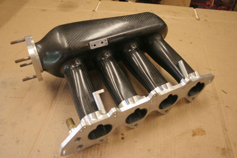
With good surface prep and the correct epoxy I don't see there being any problems.
With good surface prep and the correct epoxy I don't see there being any problems.
Reply
0
0
Junior Member
Joined: Jan 2015
Posts: 272
Total Cats: -25
That is the AIR manifold that was sold by Endyn for a short period. Even with high demand they were not able to produce reliable manifolds. The company that built the AIR manifold was a manufacturer that was very familiar with bonding carbon and aluminum and still was not able to do it reliably.
Reply
0
0
Thread Starter
Joined: Jul 2012
Posts: 792
Total Cats: 143
From: durham NC
The only thing I can see being tricky is dealing with thermal expansion being different between aluminum and composite. Otherwise, it is just a matter of surface prep and picking the correct structural epoxy.
You could also drill a hole through the flange and the and the carbon and then press fit a short aluminum dowel for mechanical interlock.
The throttle body flange could be made from carbon fiber or aluminum, which ever is cheaper and easier. It won't see anywhere near the same amount of heat as the flange at the head.
Reply
0
0
Junior Member
Joined: Jan 2015
Posts: 272
Total Cats: -25
The only thing I can see being tricky is dealing with thermal expansion being different between aluminum and composite. Otherwise, it is just a matter of surface prep and picking the correct structural epoxy.
You could also drill a hole through the flange and the and the carbon and then press fit a short aluminum dowel for mechanical interlock.
The throttle body flange could be made from carbon fiber or aluminum, which ever is cheaper and easier. It won't see anywhere near the same amount of heat as the flange at the head.
You could also drill a hole through the flange and the and the carbon and then press fit a short aluminum dowel for mechanical interlock.
The throttle body flange could be made from carbon fiber or aluminum, which ever is cheaper and easier. It won't see anywhere near the same amount of heat as the flange at the head.
Graphite fiber has a negative coefficient of thermal expansion, but can be adjusted with specific epoxies to near zero. So the thermal expansion of the Aluminum will be more of a concern. There are semi-flexable bonding agents you can use to adhere the carbon to the aluminum but the vibration will cause fatigue over time.
Reply
0
0


