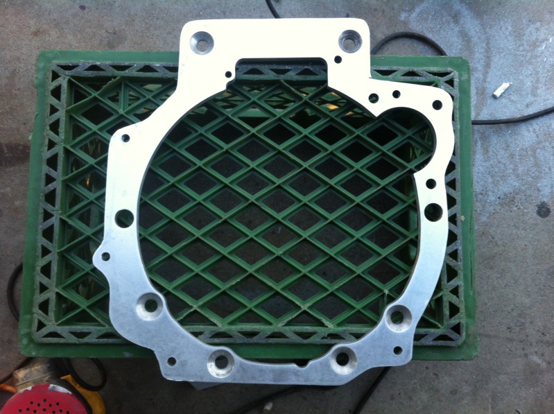
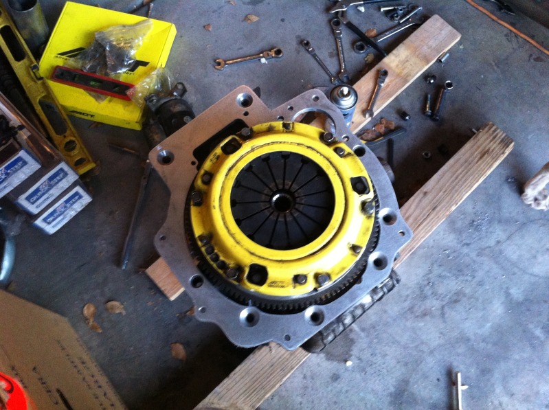
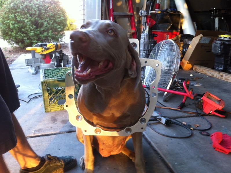
TII Transmission Adapter plate
#41
Elite Member

iTrader: (9)
Join Date: Jun 2006
Location: Chesterfield, NJ
Posts: 6,898
Total Cats: 399
And is your .010 @ MMC (which I assume is to the respective dowel hole basic dimensions) 'good enough'? I have no idea but I would guess that it is fine. Regardless, if you are doing it on a CNC then the holes will be done in one operation so the positional tolerance will be whatever the machine can hold, well well within that.
You made it seem the laser scan was of the prototype part which was done with basic tools. I can carve something with my hacksaw then laser scan it to make excellent accurate copies of my not-so accurate initial part. My mistake!
You made it seem the laser scan was of the prototype part which was done with basic tools. I can carve something with my hacksaw then laser scan it to make excellent accurate copies of my not-so accurate initial part. My mistake!
#43
Hey guys, I just wanted to come in here and clear up some confusion.
I'm helping Pat in designing this part and I was one of the original designers of the SR20 adapter he posted earlier.
The original plate has lasted 3+ years and 550whp without any problems. I think that in itself speaks volumes.
The plate is laser scanned and then we have it CNC cut on a HAAS vertical milling center. As you know the tolerances of the machine are .0001" or better. Since everything is done on a single operation the tolerance is held much tighter than the .010" specified. Even at .010" the position can only vary .005" due to the positional tolerance. On a large part like an adapter plate .005" is nothing. That's half a human hair. Pretty sure the OEM tolerances on a cast block are not this good.
And since we already have the plate and it fit perfectly. Dowel pins lined up and all the bolts are dead on I can say that the part is accurate.
ps. I'm a design engineering with 6+ years of doing work just like this. Solidworks certified as well as Camworks. When Pat asked for this I figured I'd help him out and save him from having to "hacksaw" anything.
#44
Elite Member

iTrader: (9)
Join Date: Jun 2006
Location: Chesterfield, NJ
Posts: 6,898
Total Cats: 399
Hey guys, I just wanted to come in here and clear up some confusion.
I'm helping Pat in designing this part and I was one of the original designers of the SR20 adapter he posted earlier.
The original plate has lasted 3+ years and 550whp without any problems. I think that in itself speaks volumes.
I'm helping Pat in designing this part and I was one of the original designers of the SR20 adapter he posted earlier.
The original plate has lasted 3+ years and 550whp without any problems. I think that in itself speaks volumes.
The plate is laser scanned and then we have it CNC cut on a HAAS vertical milling center. As you know the tolerances of the machine are .0001" or better. Since everything is done on a single operation the tolerance is held much tighter than the .010" specified. Even at .010" the position can only vary .005" due to the positional tolerance. On a large part like an adapter plate .005" is nothing. That's half a human hair. Pretty sure the OEM tolerances on a cast block are not this good.
And since we already have the plate and it fit perfectly. Dowel pins lined up and all the bolts are dead on I can say that the part is accurate.
ps. I'm a design engineering with 6+ years of doing work just like this. Solidworks certified as well as Camworks. When Pat asked for this I figured I'd help him out and save him from having to "hacksaw" anything.
ps. I'm a design engineering with 6+ years of doing work just like this. Solidworks certified as well as Camworks. When Pat asked for this I figured I'd help him out and save him from having to "hacksaw" anything.
Maybe by chance/skill you were more accurate with the transfer punches when you made your 550whp adapter.
I don't mean to ---- on your thread, just playing devil's advocate. We need parts like this. The original 5 speed sucks, 6 speed is expensive and I don't like the ratios, etc.
#46
All this discussion about accuracy is what I was getting at when I asked about the alignment of the input shaft and crankshaft.
When I made my adapter plate, I didn't have access to a laser scanner or CMM. What I ended up doing is use the DRO on a cnc (Matsuura too) to plot all the holes and then CAD'ed everything out that way. I made sure to get the input shaft and dowel pins exact. Took a while to find the centers of all the hole locations, but the end result fit perfectly.
--Ferdi
#48
Elite Member

iTrader: (9)
Join Date: Jun 2006
Location: Chesterfield, NJ
Posts: 6,898
Total Cats: 399
All this discussion about accuracy is what I was getting at when I asked about the alignment of the input shaft and crankshaft.
When I made my adapter plate, I didn't have access to a laser scanner or CMM. What I ended up doing is use the DRO on a cnc (Matsuura too) to plot all the holes and then CAD'ed everything out that way. I made sure to get the input shaft and dowel pins exact. Took a while to find the centers of all the hole locations, but the end result fit perfectly.
--Ferdi
When I made my adapter plate, I didn't have access to a laser scanner or CMM. What I ended up doing is use the DRO on a cnc (Matsuura too) to plot all the holes and then CAD'ed everything out that way. I made sure to get the input shaft and dowel pins exact. Took a while to find the centers of all the hole locations, but the end result fit perfectly.
--Ferdi

Haha nice!
#54
Elite Member

iTrader: (9)
Join Date: Jun 2006
Location: Chesterfield, NJ
Posts: 6,898
Total Cats: 399
But you would like to sell the bellhousing adapter for around $400, which I think is a great price BTW. The material alone should be ~40-50% of that price.
So I'll ask, what are YOU going to do for a differential mount, transmission mount, and driveshaft, even if you don't plan to sell it as a kit? People who are considering your plate may benefit from that info.
So I'll ask, what are YOU going to do for a differential mount, transmission mount, and driveshaft, even if you don't plan to sell it as a kit? People who are considering your plate may benefit from that info.
#55
I'll chime in here again.
It's simple enough to fab a pinion mount for the diff. I bent a piece of 5/16" and welded it directly to the subframe. I think it was mentioned, but there are a ton of different "options" a lot of the v8 guys are using to secure the diff, ranging from hacked up ppf mounts, to heim joint linkages, to simple designs like mine. I doubt you'll be able to retain the ppf, but if you figure out a way, more power to you. I haven't missed mine one bit.
Concerning the driveshaft, if you will be retaining the miata diff, just bring the rx7 and the miata shafts down to a driveshaft shop (after measuring the length from the pinion flange to the trans output), and have him chop the ends off, weld the miata one onto the rx7 shaft, and balance them out. Shouldn't cost more than $40.
I covered what needs to be done to swap in an rx7 diff in my build thread, if you want to go that route. It's just one of many ways, but I still feel it's the easiest, and requires the least amount of "custom" parts.
Concerning the wiring on the transmission, when running megasquirt, the only thing that needs to be hooked up is the reverse lights. I left everything else unplugged. I also removed all the rx7 sensors and installed the miata ones. Everything works as expected.
As for the speedo cable, I used the miata cable and just put it on the rx7 speedo gear, it fits right in without issue. It's on the opposite side of the transmission, but there is enough slack to get it over there.
For the rear transmission mount (assuming you'll be ditching the PPF), I flipped the OEM rx7 trans mount 180 degrees, as the exhausts are on opposite sides (rx7 vs miata). From there, just bend up some brackets and weld them to the tunnel. The trans tunnel is double walled, so you can put some good heat into it. The floor boards aren't however.
I think I covered all your questions, but if not let me know.
#57
Question for all of you Mazda transmission experts. My roommate had his Miata's 5 speed rebuilt with "RX-7" gears. I am not sure even he knows which year or model they are from, I just know they are much longer than the stock 5 speed. But are the TII gears significantly bigger than other RX-7 models that they would't fit in the Miata's transmission case? I assume they don't, or you wouldn't be going through with all of this trouble to build an adapter plate.
#58
Question for all of you Mazda transmission experts. My roommate had his Miata's 5 speed rebuilt with "RX-7" gears. I am not sure even he knows which year or model they are from, I just know they are much longer than the stock 5 speed. But are the TII gears significantly bigger than other RX-7 models that they would't fit in the Miata's transmission case? I assume they don't, or you wouldn't be going through with all of this trouble to build an adapter plate.
#59
Sweet, thanks. I just finished reading your build thread, very nice. Now you just need to change the link in your sig to one that works. Try this one: Build thread
And if they get this adapter plate figured out, I will probably use something similar to your bracing if I decide to go with a TII transmission (which I probably will).
And if they get this adapter plate figured out, I will probably use something similar to your bracing if I decide to go with a TII transmission (which I probably will).


