
GB Fully Assembled Miata Dwell Reducer Boards


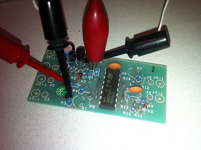
 They are pretty tiny, I remember thinking that myself when I deboxed the boards.


Newb
Joined: Feb 2013
Posts: 17
Total Cats: 0
I have been looking and have not found much success in finding someone selling them. But if your making some Im interest. please let me know. also are you in the bay area? I think i can recall you being in san jose.
Reply
 0
0

0


Senior Member
Joined: Dec 2004
Posts: 1,278
Total Cats: 37
From: Brisbane, Australia
Jason, I had a place build a batch of them but they didn't work as expected. One of the guys doing the testing reported back with this:
I tested them on the bench using a PIC, but only ever tested one channel at a time:
Testing rig:

Testing 'A' part of board:
If you get a chance I'd love to hear your feedback!
I ordered from an earlier BOM but had a later revision of your PCB layout file, hence the jumpers. Does the later revision incorporate the above fixes?
Cheers
An Electronic Engineer friend (who now wants me to "look" at his rear suspension) has helped me find the problem an a fix.
The board works fine when only one channel is opperating but not when both channels are opperated simultaneously. The problem is the reference voltage to the opp. amps is not stable and gets worse when both channels opperate, to the point where the "tipping" voltage is not reached.
The quick fix is to solder a 47uf capacitor across R6. This stabilises the reference voltage and allows both channels to work simultaneously. However, as the frequency (engine speed) increases, the "averaged" reference voltage will increase and the delay time (dwell reduction) increases. On my board, the delay time varried from 1 to 1.2 ms over the expected engine speed range (it was 1.6ms when only one channel was opperated).
A better fix would be to replace R5 and R6 with 1k ohm resistors and add the capacitor across R6. This will reduce the influence of the opp. amps input impedance and reduce the change in dwell time with frequency.
A possible even better fix would be to replace R6 with a Zina diode as well as the above, but you may need to change the R/C circuits to return to the desired delay time, depending on the voltage drop of the diode.
Bottom line, you will need to change the boards to make them work.
Testing rig:
Testing 'A' part of board:
If you get a chance I'd love to hear your feedback!
I ordered from an earlier BOM but had a later revision of your PCB layout file, hence the jumpers. Does the later revision incorporate the above fixes?
Cheers
Reply
0
0


Junior Member
Joined: Mar 2012
Posts: 298
Total Cats: 44
I think most people just go for a standalone ECU where the board isn't needed.
Stock ECU is fine with stock coils.
If for some reason you really want one of the boards I think I still have one of the Timk ones rattling around a drawer in my toolbox.
Never used it, and you'll still need to do the changes Tim mentions in his post above.
In saying that, you're still probably better off changing ECU, or staying fully stock.
I've never actually heard of anyone getting any of the dwell reducer boards to work. (which would probably explain why nobody sells them anymore)
Reply
0
0

Thread
Thread Starter
Forum
Replies
Last Post
kenzo42
Group Buys and Member Discounts
24
Nov 4, 2009 01:38 PM
TravisR
Group Buys and Member Discounts
306
Oct 17, 2009 02:39 PM


