
EBC mod - Writeup

Thread Starter


Joined: May 2005
Posts: 80,581
Total Cats: 4,371
From: Chantilly, VA
Reply
 0
0

0

ok, here's a quick write up for the lazy
You'll need a 3 port solenoid. Im using the solenoid from the GM Tyhpoon, as it's inexpenisve and easy to aquire. It was $32 I think from the Chevy dealer including the pigtails. The pigtails were about 60% of the cost. Since the install, I've seen the pigtails at Advanced Auto for like $6. Oh well.
OK, here you can see the solenoid (red circle). It comes with a little bracket, and I bolted it down to the Diagnostic Port bolt. The solenoid has 3 vac ports and 2 wires. One side has 2 vac ports, I marked with yellow arrows. One of these ports has a foam filter on it. Don't touch this port. The port NEXT TO the filtered port is your wastegate output. Connect it to your WG with a rubber hose. Marked with yellow arrows. The opposite side of the solenoid has one vac port and the electrical connectors. The port on this side, under the pigtails, is connected to your turbo boost source with a second rubber hose. Marked with blue arrows.
In this picture you can also see wiring exiting the solenoid, and splitting off. there are 2 wires, one goes to +12V and the other goes to the MSPNP at center connector pin #9. It does not matter which wire goes to which. You can see one of these wires traveling down towards the Diag connector (this is getting +12V) and the other goes hard right and disappears in the fender (going to MSPNP). This wire travels down the fender, across the firewall, and into the cabin through a grommit on the passenger side, then to the MSPNP center connector.

This is a blow up view of the +12V source. I opened up the Diagnostic connector and spliced into the "B+" terminal, which is a key-switched +12V source. The Diag connector pulls off of its bracket and opens from underneath, it's pretty simple. I then ran the wire back to the solenoid and wrapped it with electrical tape.

You'll need a 3 port solenoid. Im using the solenoid from the GM Tyhpoon, as it's inexpenisve and easy to aquire. It was $32 I think from the Chevy dealer including the pigtails. The pigtails were about 60% of the cost. Since the install, I've seen the pigtails at Advanced Auto for like $6. Oh well.
OK, here you can see the solenoid (red circle). It comes with a little bracket, and I bolted it down to the Diagnostic Port bolt. The solenoid has 3 vac ports and 2 wires. One side has 2 vac ports, I marked with yellow arrows. One of these ports has a foam filter on it. Don't touch this port. The port NEXT TO the filtered port is your wastegate output. Connect it to your WG with a rubber hose. Marked with yellow arrows. The opposite side of the solenoid has one vac port and the electrical connectors. The port on this side, under the pigtails, is connected to your turbo boost source with a second rubber hose. Marked with blue arrows.
In this picture you can also see wiring exiting the solenoid, and splitting off. there are 2 wires, one goes to +12V and the other goes to the MSPNP at center connector pin #9. It does not matter which wire goes to which. You can see one of these wires traveling down towards the Diag connector (this is getting +12V) and the other goes hard right and disappears in the fender (going to MSPNP). This wire travels down the fender, across the firewall, and into the cabin through a grommit on the passenger side, then to the MSPNP center connector.
This is a blow up view of the +12V source. I opened up the Diagnostic connector and spliced into the "B+" terminal, which is a key-switched +12V source. The Diag connector pulls off of its bracket and opens from underneath, it's pretty simple. I then ran the wire back to the solenoid and wrapped it with electrical tape.
Reply
0
0
I just tore out my tullos to wire this up. I'm going to assume that at the connector the brown wire coming out of the pigtail is the 12V+ and the black is the ground wire that goes to MS.
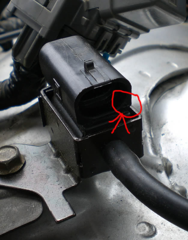
In other words. Looking at your top picture. The wires coming into the connector, the right one is GND, the left is 12v!?
Some people say they can hear the solenoid when it's running. I cut a small piece of hose and used it as a grommet to keep it from transmitting the noise.
In other words. Looking at your top picture. The wires coming into the connector, the right one is GND, the left is 12v!?
Some people say they can hear the solenoid when it's running. I cut a small piece of hose and used it as a grommet to keep it from transmitting the noise.
Reply
0
0
I don't have the first clue what colors the wires are under the electrical tape. But it doesn't matter. The solenoid doesn't care about polarity. Like a lightbulb. Just wire one side to +12V and the other to the MS. Just get the signal hoses right. 
The solenoid is a noisy little bastard. It's not transmitting noise to the chassis, it's just noisy when it switches. I hear mine when I start the car for a couple of seconds. I have the first column in my boost table set to 0 so that the solenoid doesn't do anything until like 1500 rpm, then I have it set to max duty cycle. By 1500 rpm there's plenty of engine/exhaust/road noise to drown out the solenoid.
Not on my solenoid. Maybe on yours (but you're running a different solenoid anyway).
Reply
0
0

 but either way it doesnt matter.
I thought you had one of FM's solenoids
I don't see any indicator on mine, but still it's a moot point anyway
I don't see any indicator on mine, but still it's a moot point anyway
Reply
0
0
 I stand corrected
and both the wires on my pigtail are gray, no stripe or marker
Reply
0
0
Thread Starter
Joined: May 2005
Posts: 80,581
Total Cats: 4,371
From: Chantilly, VA
Reply
0
0
I wish they would allow me to tune by TPS and KPa rather than TPS vs RPM ... that way i could have a high dutycycle until i get close to my target boost. What do you guys think? I bet if we put the word out that could be changed.
Reply
0
0
aight, i messed with closed loop for like 20 minutes last month when i first got the EBC working. So when using the closed loop, the megasquirt uses a high duty cycle until it gets close and then opens it up or something like that and i would guess that it acts like the closed loop idle with a little bit of yo-yo'n occasionally?
Reply
0
0
Bottom of the page http://www.megamanual.com/ms2/V3assemble.htm
Then again i'm wired in parallel with the stock ecu controlling idle, never could get MS to do it right. So maybe it's just my harness that's messed up and I missed something when building mine up.
So i'm going to wire the boost solenoid gnd to pin 29. Guess we'll see how it works.
Reply
0
0

Is there a reason for the IRLz44 choice? Seems like an oddball. Are they cheap? What does the MS output for gate drive? 12v or logic level? The resistor in series to the gate is just to dampen ringing right? 10ohm is most you'll need.
Just curious.
I'm using my old purge solinoid for ebc. Works great.
Just curious.
I'm using my old purge solinoid for ebc. Works great.
Reply
0
0
Reply
0
0


