
Finishing off DIYPNP, couple questions (alternator voltage regularion, sequental inj.


Thread Starter
Newb
Joined: Jan 2013
Posts: 23
Total Cats: 0
From: Finland
I have now assembled the voltage regulator circuit, but would like to test it. I have access to adjustable power supply at school.
Do i just connect ground to power supplys negative and 12v to power supplys positive, start from 12v and go up to 14.4 where it should go to zero? 500mA should be enough?
Also, i downloaded the latest ms2extra 3.3.0 firmware onto unit, and followed by uploading the basemap but its showing all these erroes. Is is normal? my usb->serial adapter is working, tunerstudio was able to detect the firmware on my unit.
https://i.imgur.com/joGI56o.png
https://i.imgur.com/9piCys6.png
Reply
 0
0

0


Thread Starter
Newb
Joined: Jan 2013
Posts: 23
Total Cats: 0
From: Finland
Tested the voltage regulation circuit at school today, with mixed results.
https://i.imgur.com/BdHAehU.jpg
Here is my connection, i set it to 500mA and 12v DC. Couple times it cut the voltage on "field out" at ~15.2v but the multimeter didint give me a voltage.
Ones it cut at ~14.4v and after that it refused to cut the voltage. I went up to 17v without results.
I have double-triple checked everything, all components should be in right places and i dont have shorts.
My local eletronics store didint have PN2907A, insted i used 2N2905A transistors. Could this be the problem?
Here is a closer look to my circuit
https://i.imgur.com/wkJcTbw.jpg
https://i.imgur.com/6HEwn4T.jpg
Looks chaotic, but nothing is actually touching and shorting out.
12v and gnd was too hard to jump, so i modified the circuit a bit
https://i.imgur.com/9Uf6rr9.jpg
It should still work the same..?
Reply
0
0

Sorry if it feels like i'm bringing this thread back from the dead.
Where did ya'll get the components to build the alternator control circuit? Any website you have good luck with? I tried Radioshack (really the only place in town) but they didn't have a bunch of the parts.
Thanks
Where did ya'll get the components to build the alternator control circuit? Any website you have good luck with? I tried Radioshack (really the only place in town) but they didn't have a bunch of the parts.
Thanks
Reply
0
0

Eric,
I got mine from Fry's in Duluth... Wait, when did you move from L'ville to Florida?
Try an online parts supplier such as digikey or mouser. I would expect Radioshack to be a bust.
I got mine from Fry's in Duluth... Wait, when did you move from L'ville to Florida?
Try an online parts supplier such as digikey or mouser. I would expect Radioshack to be a bust.

Reply
0
0
Well its been a few years now. And yeah Frys's would be my go to place if I were still is L'ville. Just ordered everything through digikey. I just hope I ordered everything correctly. There is a lot of **** on there.
Reply
0
0
Thread Starter
Newb
Joined: Jan 2013
Posts: 23
Total Cats: 0
From: Finland
Bought my components off a local store, but didint actually get the regulator to work. Ordered one off westfield, works great.
Alternator pcb | Frank's Westfield MX5 Alternator pcb |
Alternator pcb | Frank's Westfield MX5 Alternator pcb |
Reply
0
0
Thread Starter
Newb
Joined: Jan 2013
Posts: 23
Total Cats: 0
From: Finland
Reply
0
0

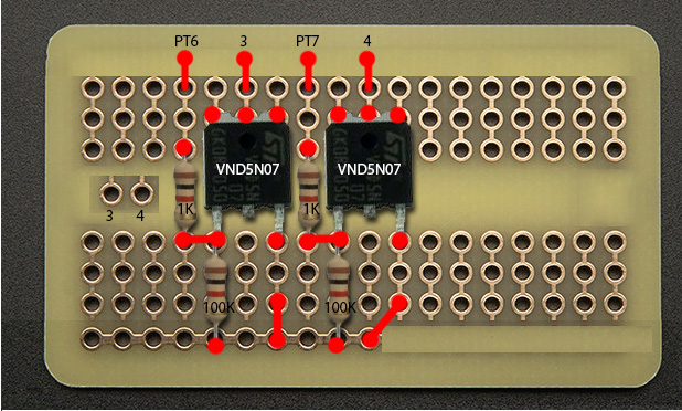
find the microcircuit module schematics and duplicate the inj outputs.
its a driver a 100k reisistor and a 1K resistor. that's it.
its a driver a 100k reisistor and a 1K resistor. that's it.
Last edited by Braineack; Feb 28, 2015 at 06:23 PM.
Reply
0
0

Junior Member
Joined: Dec 2010
Posts: 87
Total Cats: 0
From: Greenville SC
Sorry if it feels like i'm bringing this thread back from the dead.
Where did ya'll get the components to build the alternator control circuit? Any website you have good luck with? I tried Radioshack (really the only place in town) but they didn't have a bunch of the parts.
Thanks
Where did ya'll get the components to build the alternator control circuit? Any website you have good luck with? I tried Radioshack (really the only place in town) but they didn't have a bunch of the parts.
Thanks

New alternator too much? used ones are really el cheapo.
Reply
0
0
Reply
0
0

Senior Member
Joined: Nov 2007
Posts: 999
Total Cats: 73
From: Belgium
This is heresy but I just put a 97 or back alternator with a built in regulator made of much stouter stuff than whatever you can solder to that board. In over half a million miles of miata driving (wife, son and my miatas) never had a regulator go out yet. Bearings, well, not so good
New alternator too much? used ones are really el cheapo.
New alternator too much? used ones are really el cheapo.
Measure yours some time.
Reply
0
0

Newb
Joined: Feb 2015
Posts: 14
Total Cats: 0
From: Tuscaloosa, AL
Thank you for posting this. I was able to follow the traces and map out the circuit using DIY's photo, but liked to see how it was laid out on the proto area. I know this is probably a super noob question, but the DIY sequential board has holes INJ3 and INJ4 to go right to the connector board, but I see that you wire yours into the 3 and 4 right there on the proto area. How do you get that back to the 4V and 4X on the connector board?
Reply
0
0

Thread
Thread Starter
Forum
Replies
Last Post


