When you click on links to various merchants on this site and make a purchase, this can result in this site earning a commission. Affiliate programs and affiliations include, but are not limited to, the eBay Partner Network.
So I bought this MS2 on impulse, planning to use it on an essentially stock 1.6. Was told it was built for a Miata, then modified for rotary use, then used on a 1.8 swapped Miata again. So I need to figure out what's been done to it and how the I/Os are set up before anything else. Going through the assembly guide in the manual, I've determined the basics:
-PWM idle installed
-VR input installed
-High current ignition driver NOT installed
-PWM flyback damping circuit installed (for low-Z injectors)
-Standard flyback circuit is MISSING Q3, Q11 (?)
-Current limit circuit for FET protection installed
But I'm not really sure what's going on in the proto area. It doesn't really match the DIYAutotune guide, or what's in the wiki here. Or the reason for the jumper on the daughter card.
Does anyone recognize this configuration? Or should I remove it all and redo it?
you dont want to install the high-current driver for fuel. just send FP out to 2O, and jump the connection in the AFM connecter (see my sig).
pic 1: Table Switching mod.
pic 2: PWN idle mod is missing a flyback diode.
pic 3, 4 & 5: proto area: I've never seen them modded in this manner but it's the standard spark 1, fan, spark 2 on the LEDs. pink wire appears to be the input for the table-swtiching.
looks like it's missing the second trigger for the CAS -- I only see the single VR input being used.
spark output need to be set to non-inverted (normal) for this setup.
Thanks so much, Brain! You got me pointed in the right direction.
Now I understand:
-IAC1A is a ground switch input to JS7 (tableswitch, launch)
-IAC2A is fan output from D15
-IAC2B is SPK2 output from D16
-D14 is SPK1 output - it runs to IGN, where does this output on the DB37? The normal ignition output (pin 36)?
-I agree on the missing PWM idle diode, will fix
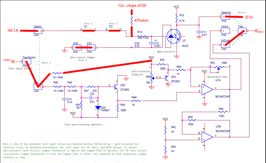
-If crank input is set up with TACHSELECT<>VRIN and TSEL<>VROUT, is this the correct cam input circuit to add for a CAS? CAM to JS10 thru 1kohm, 5V to CAM thru 470ohm
And this leaves me with IAC1B, SPR3, and SPR4 as spare pins for JS4, JS5, and JS11 I/Os? And I can connect those pins to the I/Os as long as I add the proper conditioning circuit in between, correct?
Dude. Thanks.
Didn't realize both those circuits can be used at once - added opto for cam according to that diagram. So I'm using the existing table switch input for AC in, and I added output for AC, and input for the clutch switch. I also added the missing PWM idle flyback diode, and Q3 and Q11 which were missing. I think it's all ready to go in the car now - I just want to confirm that these spark settings are correct for this board and a stock 1.6:
I've also noticed that U5 gets very hot to the touch after the unit is powered on for a few minutes with these settings. Is this normal? I see this is the power supply voltage regulator - maybe a short somewhere, or it needs a fresh application of thermal paste?
Just a quick follow up to this since people always forget to do so - I got the car running on this unit today!
The ignition settings above were correct after I changed to rising edge.
I added the opto-in circuit for cam input like Brain posted above, and it worked perfectly. However, at first I had no crank signal. Found that the VR circuit was missing the 5V pullup, so I added that. Still had no signal, but simply readjusting the pots by counting turns fixed it immediately, and the car started.
Also had no MAP signal - was sitting at ~20kpa, the board wasn't getting voltage from the sensor. I thought I had a bad trace from the MAP to R2, but reflowing the solder on the MAP sensor signal pin restored continuity between them. Weird. The area around those pads is kind of brown, apparently the sensor was replaced (poorly) at some point.
I forgot to get a wideband so I only idled it for a few minutes. Stock narrowband really is useless. All the i/o seems to work now, other than the AC and launch circuits which I haven't tested yet. I only noticed two idiosyncrasies - sometimes the fan comes on at key on, and sometimes it doesn't. Also, whenever a change is burned, the engine shuts off, unlike my MS3. I assume these are both just MS2 things but I'll google them later.
 06-17-2018, 09:17 PM


 0
0