
Help tracking down MS3 wiring issues/diagram


Elite Member
Joined: Mar 2006
Posts: 1,574
Total Cats: 106
From: Schwarzenberg, Germany
He even has one spare pin at the connector for the knock sensor.
+1 on the flyback diodes for boost and idle!
Reply
 0
0

0


Reply
0
0
Elite Member
Joined: Mar 2006
Posts: 1,574
Total Cats: 106
From: Schwarzenberg, Germany
I think that is the next step anyway to propose him a nice wiring for his setup.
He needs a nice VICS connector anyway, so I think he should order some spare pins for the 12pin connector as well. (at Ballenger Motorsports)
@Jeff how did you wire your wideband to +12v, ground and how was the old wideband wired in at the OEM connector 4 pin 4N? (I would suggest using one of the 12pin connector +12V and grounds for the wideband - so that the WB has the same grounds as the MS3)
Greets
Sven
Reply
0
0

Thread Starter
Elite Member
Joined: Oct 2013
Posts: 2,764
Total Cats: 951
From: Cedar City, UT
So the original owner didn't have diodes in place for the EBC and AFR?
I need to research what the hell a flyback diode is as well. I have a new VIC's connector in my shopping cart at the moment but just let me know what else I should add and I'll get the order rolling.
Does this mean I need to solder something onto the board itself? If so, I'm not sure I have the skills to do that precise of a soldering job unless all it takes is, pre-tinnng the wire, and then remelting the solder once placed in the board pin hole?
I'm headed down to st George tonight so I'll take a look at injector wiring to corroborate firing order of 1&3 and 2&4.
Reply
0
0
Thread Starter
Elite Member
Joined: Oct 2013
Posts: 2,764
Total Cats: 951
From: Cedar City, UT
Just need to know where the analog+ wires for the wideband and boost go on the ms3.
_*edit* believe the old wideband was hooked up to the 12 pin connector on the DIYBOB. Not sure where though.
Reply
0
0

Elite Member
Joined: Mar 2006
Posts: 1,574
Total Cats: 106
From: Schwarzenberg, Germany
Hi Jeff,
I tried to make you a little wiring scheme for the extra harness you should make:
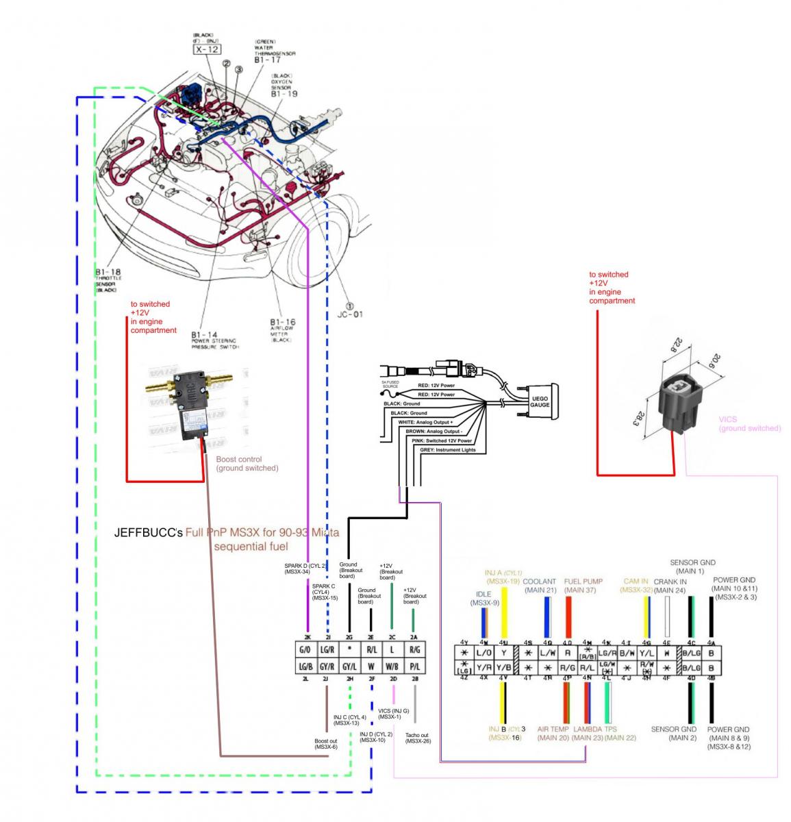
I hope it is somewhat understandable. It also might need some work.
Questions for Brain and the other MS cracks:
- I think he could also use the +12V sources on Connector 2 for the VICS and for the EBC valve?
- Where does the Tach out usually go to on the 93 Miata?
Jeff, I think you should order:
- the VICS connector kit:
Home � Shop � Connectors / Harnesses � Sumitomo � 2 way Japanese Solenoid Connector Kit (Miata VICS)
- some spare connector pins for the 12pos connector Nr.2
.040" Contacts (175061-1) Tyco
- a bunch of wires in the correct length (2-3m ?) to get to the injectors/coils/EBC/VICS in different colours
I think that is about it.
(On a side note - I would have wired the AEM to the Connector Nr. 2 for +12V, grounds and maybe I would have moved the O2 input from connector Nr.4 to the spare port on Nr. 2 - but that is just me...)
I tried to make you a little wiring scheme for the extra harness you should make:
I hope it is somewhat understandable. It also might need some work.
Questions for Brain and the other MS cracks:
- I think he could also use the +12V sources on Connector 2 for the VICS and for the EBC valve?
- Where does the Tach out usually go to on the 93 Miata?
Jeff, I think you should order:
- the VICS connector kit:
Home � Shop � Connectors / Harnesses � Sumitomo � 2 way Japanese Solenoid Connector Kit (Miata VICS)
- some spare connector pins for the 12pos connector Nr.2
.040" Contacts (175061-1) Tyco
- a bunch of wires in the correct length (2-3m ?) to get to the injectors/coils/EBC/VICS in different colours
I think that is about it.
(On a side note - I would have wired the AEM to the Connector Nr. 2 for +12V, grounds and maybe I would have moved the O2 input from connector Nr.4 to the spare port on Nr. 2 - but that is just me...)
Reply
0
0
I wouldn't use the center connector source for VICS or EBC only becuase I wouldn't want to redundantly wire 12v to the engine bay...it's the same white/red source found throughout.
coils.
coils.
Reply
0
0
Elite Member
Joined: Mar 2006
Posts: 1,574
Total Cats: 106
From: Schwarzenberg, Germany
 ... do it on the DIYBOB a little piece of wire and a 1K resistor with some heatshrink from 1B to 4I.
Reply
0
0
Thread Starter
Elite Member
Joined: Oct 2013
Posts: 2,764
Total Cats: 951
From: Cedar City, UT
Connectors ordered. I also ordered a new 12 pin connector for the DIYBOB to help clean up the mess that is that connector.
When I wired my COP harness it had a capacitor on the ground and VB wires before the Mitsubishi Power Unit, just wanted to make sure that was correct.
And I'm not really ADDING COPS, since it had it before the car was wrecked. I merely cleaned up the wiring by making a new harness.
I'll check out moving some of the AEM wiring to the correct spots tonight.
Reply
0
0
Thread Starter
Elite Member
Joined: Oct 2013
Posts: 2,764
Total Cats: 951
From: Cedar City, UT
It looks like injectors 1&2/3&4 are paired to each other with a resistor between each. The car already had sequential injection(from the build sheet) so I'm guessing I don't need to rewire it.
Should I pull the upper intake manifold and trace the wiring back to the ECU harness just to make sure?
Should I pull the upper intake manifold and trace the wiring back to the ECU harness just to make sure?
Reply
0
0
Thread Starter
Elite Member
Joined: Oct 2013
Posts: 2,764
Total Cats: 951
From: Cedar City, UT
I'm hopeful that they are, when I bought the car he said they were, but with the other wiring maladies the car had, I think pulling the wiring out just for peace of mind will be the safest bet.
Reply
0
0
Thread Starter
Elite Member
Joined: Oct 2013
Posts: 2,764
Total Cats: 951
From: Cedar City, UT
What is the correct amperage of the flyback diode needed?
From what I have read a 1N4004 diode is what people are using correct?
1N4004 Micro 1-Amp Rectifier Diode : Diodes | RadioShack.com
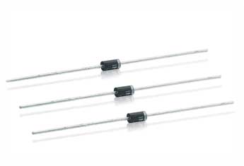
From what I have read a 1N4004 diode is what people are using correct?
1N4004 Micro 1-Amp Rectifier Diode : Diodes | RadioShack.com
Reply
0
0


