
I'm thinking about a VVT swap in my daily


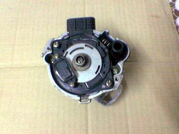
This is a 4/1 CAS but you get the idea.
You can't run an engine without knowing the crank position period. Cam position is just to know which 360deg phase the engine is in (as a full cycle is 720deg i.e. 2 turns of the crank for 1 turn of the cam.
That's why a CAS is shitty for accuracy, it's sat on the cam which is driven by a semi flexible rubber belt from the crank, hello timing jitter as the belt stretches and relaxes.
The tach is either driven by the ECU on later MK1's or by the igniter module.
Reply
 0
0

0


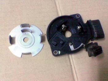
There are 2 rings on the Miata CAS...
CKP cranK position 4 teeth
CMP caM position 2 teeth
The CKP ring has 1 tooth per cylinder and presumably is used by the stock computer for its RPM and timing calculations. The CMP ring has 2 uneven teeth that would be used to determine engine phase--IE each cylinder has 2 TDC events per cycle. For sequential fuel and/or distributorless ignition, we need to know better crank position info, and for sequential we need to know if the TDC event is on compression or exhaust stroke.
Since the CAS is driven at cam speed, yes you could use only one ring with a missing tooth, but I'm guessing the 80's era technology Miata ECU wasn't up to the job.
However not sure what's going on here. Are you running MS3X on a VVT motor (that's what I thought your plan was). If so, you do NOT NEED the NA Miata CAS at all. You would use the NB crank and cam sensors, which are separate sensors on the NB engine.

Reply
0
0

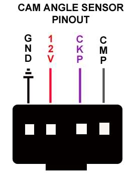
95 CAS sensor Plug Colors
Yellow/Blue - Cam Signal
White - Crank Signal
White/Red - Power
Black/Light Green - Ground
99 Cam Sensor Wires
White/Red - Power
Grey/Blue - Cam Signal
Black/Blue - Ground
99 Crank Sensor Wires
White/Red - Power
Grey/Red - Crank Signal
Black/Blue - Ground
So to hook the NB Sensors up to the NA wires you need to do the following.
Black/Blue from both Cam/Crank plugs goes to Black/Light Green
White/Red from both Cam/Crank plugs goes to White/Red
Grey/Blue from Cam goes to Yellow/Blue
Grey/Red from Crank goes to White
For VVT you run one of the wires to the White/Red wire on the CAS.
The other wire gets ran back to your MS connector. I am not sure how Reverent will have you hook it up, but he should be able to give you more details.
Reply
1
1
Thread Starter
Joined: Jun 2006
Posts: 29,085
Total Cats: 375
From: Republic of Dallas
There are 2 rings on the Miata CAS...
CKP cranK position 4 teeth
CMP caM position 2 teeth
The CKP ring has 1 tooth per cylinder and presumably is used by the stock computer for its RPM and timing calculations. The CMP ring has 2 uneven teeth that would be used to determine engine phase--IE each cylinder has 2 TDC events per cycle. For sequential fuel and/or distributorless ignition, we need to know better crank position info, and for sequential we need to know if the TDC event is on compression or exhaust stroke.
Since the CAS is driven at cam speed, yes you could use only one ring with a missing tooth, but I'm guessing the 80's era technology Miata ECU wasn't up to the job.
However not sure what's going on here. Are you running MS3X on a VVT motor (that's what I thought your plan was). If so, you do NOT NEED the NA Miata CAS at all. You would use the NB crank and cam sensors, which are separate sensors on the NB engine.
CKP cranK position 4 teeth
CMP caM position 2 teeth
The CKP ring has 1 tooth per cylinder and presumably is used by the stock computer for its RPM and timing calculations. The CMP ring has 2 uneven teeth that would be used to determine engine phase--IE each cylinder has 2 TDC events per cycle. For sequential fuel and/or distributorless ignition, we need to know better crank position info, and for sequential we need to know if the TDC event is on compression or exhaust stroke.
Since the CAS is driven at cam speed, yes you could use only one ring with a missing tooth, but I'm guessing the 80's era technology Miata ECU wasn't up to the job.
However not sure what's going on here. Are you running MS3X on a VVT motor (that's what I thought your plan was). If so, you do NOT NEED the NA Miata CAS at all. You would use the NB crank and cam sensors, which are separate sensors on the NB engine.
I'm putting MS2 on my daily driver (whatever that car may be in the next two weeks), and hopefully doing MS3 on my turbo car when that time comes.
The other thing I don't understand is CMP on a VVT cam. If the cam is advanced or retarded, is there an algorithm in place to interpret that synch adjustment and will that alter fuel injector firing?
Reply
0
0
Thanks. I understand all that, I don't really understand if the computer reads the squarewave through the GND wires or through the "signal" wires.
I'm putting MS2 on my daily driver (whatever that car may be in the next two weeks), and hopefully doing MS3 on my turbo car when that time comes.
The other thing I don't understand is CMP on a VVT cam. If the cam is advanced or retarded, is there an algorithm in place to interpret that synch adjustment and will that alter fuel injector firing?
MS3X or MS2 plus VVTuner can command relative position of the VVT cam. You can use timed injection with either solution to fire your injector pulses relative to crank angle based on engine load and RPM. Cam timing adjustment is an independent adjustment.
Reply
0
0
Thread Starter
Joined: Jun 2006
Posts: 29,085
Total Cats: 375
From: Republic of Dallas
Also "a ground is a ground" doesn't jive with Matt and Jerry's book in regards to precision instruments...or maybe I'm over-thinking it.
Reply
0
0
I had already assumed that you were not planning on stripping the end of the ground wire off and running it around a self tapping screw into the body.
Reply
0
0
Below are the wiring diagrams for your 95 miata and for an 01. I am not positive if you have the connectors for the NB cam/crank sensors from a 99 harness or an 01+. If you have an 01+ harness the colors will be different. Just know that the center pin on the connector is the signal wire that hooks to the stock CAS wiring.
95 System Wiring Diagram
01 Wiring Diagram
95 System Wiring Diagram
01 Wiring Diagram
Reply
0
0
Thread Starter
Joined: Jun 2006
Posts: 29,085
Total Cats: 375
From: Republic of Dallas
You're over thinking it here. I didn't say that a ground is a ground, and that all grounds are equal. I sad the hall sensor's ground wire is a ground wire. You asked if it is a ground or if it carries signal. It's a ground. Just hook it back to the MegaSquirt's sensor return with the other sensor grounds.
I had already assumed that you were not planning on stripping the end of the ground wire off and running it around a self tapping screw into the body.
I had already assumed that you were not planning on stripping the end of the ground wire off and running it around a self tapping screw into the body.
Reply
0
0
Thread Starter
Joined: Jun 2006
Posts: 29,085
Total Cats: 375
From: Republic of Dallas
Below are the wiring diagrams for your 95 miata and for an 01. I am not positive if you have the connectors for the NB cam/crank sensors from a 99 harness or an 01+. If you have an 01+ harness the colors will be different. Just know that the center pin on the connector is the signal wire that hooks to the stock CAS wiring.
95 System Wiring Diagram
01 Wiring Diagram
95 System Wiring Diagram
01 Wiring Diagram
Reply
0
0
Here is the website.
Reply
0
0
Reply
0
0
Thread Starter
Joined: Jun 2006
Posts: 29,085
Total Cats: 375
From: Republic of Dallas
That's all I needed to know, thanks. I'm not really sure if VVT in my car will come to fruition. I am considering the 99-head as a no-cost option vs trying to find the head, pay $200-500, and so on.
Reply
0
0
Thread Starter
Joined: Jun 2006
Posts: 29,085
Total Cats: 375
From: Republic of Dallas
Is this head going to give me $200 of pleasure or more frustration? I'm a little intimidated by all the wiring and sensor configuration. Can I run a 1994 coil pack on this ****** too?
Last edited by hustler; Oct 4, 2011 at 02:10 PM.
Reply
0
0


