Notices
MEGAsquirt A place to collectively sort out this megasquirt gizmo

MS3, MS3x, for a 2002. What to buy?

Old Jan 26, 2011 | 08:33 AM
  #21  
Braineack's Avatar
Boost Czar
iTrader: (62)
 
Joined: May 2005
Posts: 80,552
Total Cats: 4,368
From: Chantilly, VA
Default

Originally Posted by skidude
I've got the MS, and I've started building. I just got to step 50, and I wanted to make sure I'm reading the schematic right... all the resistors and stuff I need is already in the kit, right?
no, not at all. maybe some spare 10Ks.

Parts will cost your $4 shipped at digikey.com

This picture shows in green what would normally go there, and in gray what I'm installing, right?
It's the stock schematic with the new components added to it, follow the text to the left, that helps put it into perspective, look at his images.

And for future parts, do I need any pieces that didn't come with the kit?
Well the above input mod parts, and all the components for the Alternator control, yes. Things like Idle control and boost control can be handled with the MS3X expander board.


Here's an MS2 I did with that circuit so you can get an idea of all the mods you need to do (Take in mind there's a lot more circuits on that board than you'll need when using the MS3X card):


If he wanted to go MS3, all he would have to do is remove the ms2 daughter board and replace with the MS3 and flash the firmware. He could even load his MS2 MSQ and be on his way in like ten minutes.
Old Jan 30, 2011 | 01:48 PM
  #22  
WestfieldMX5's Avatar
Senior Member
 
Joined: Nov 2007
Posts: 999
Total Cats: 73
From: Belgium
Default

yes, green is what is there in the original design. Gray is what you'll be installing instead.
Old Feb 8, 2011 | 06:09 PM
  #23  
skidude's Avatar
Thread Starter
Elite Member
iTrader: (3)
 
Joined: Apr 2008
Posts: 2,023
Total Cats: 19
From: Outside Portland Maine
Default

Originally Posted by Braineack
There is no need to do "Joe's Spark Circuit".

When you buy the MS3 kit and MS3x, they come with the DB37 connectors you need to make a harness. Talk to y8s about the mazda ECU connector, I think he has a spare.

The Input Circuit you DO need to add is this one outlined here: http://westfieldmx5.devocht.com/index.php?section=35
see Step 50.

You will also need to do the alternator control circuit outlined above.

Also very little needs actually be populated on the mainboard, so save yourself the trouble when building it and omit the circuits that are pointless. It should also be outlined on the build thread linked above.


Don't follow any other "additional/optional circuits" or the step 65.
I just got to the step 80, does that count as an additional/optional circuit?
Old Feb 8, 2011 | 06:24 PM
  #24  
skidude's Avatar
Thread Starter
Elite Member
iTrader: (3)
 
Joined: Apr 2008
Posts: 2,023
Total Cats: 19
From: Outside Portland Maine
Default

Wow, I'm also intimidated by the alternator circuit. That seems like a lot of crap to fit in the proto area, not to mention I don't know how I'll fit 3 wires into those holes.
Old Feb 8, 2011 | 10:23 PM
  #25  
y8s's Avatar
y8s
DEI liberal femininity
iTrader: (8)
 
Joined: Jun 2005
Posts: 19,338
Total Cats: 574
From: Fake Virginia
Default

Originally Posted by skidude
Wow, I'm also intimidated by the alternator circuit. That seems like a lot of crap to fit in the proto area, not to mention I don't know how I'll fit 3 wires into those holes.
The alternator circuit needs a variable power supply to verify that it works right.

I built mine on a small piggyback board.
Old Feb 8, 2011 | 11:01 PM
  #26  
Eric13's Avatar
Newb
 
Joined: Oct 2010
Posts: 31
Total Cats: 0
Default

I'm in the same boat on not sure what all I need. Only I have a 91, is there anything else besides buying the MS3 and MS3X unassembled kit? I'm just
Old Feb 9, 2011 | 05:18 PM
  #27  
skidude's Avatar
Thread Starter
Elite Member
iTrader: (3)
 
Joined: Apr 2008
Posts: 2,023
Total Cats: 19
From: Outside Portland Maine
Default

Any idea where I can get an MS3 base map for an 02? I'm still working with the stim but I'm having trouble getting it to sync or show anything, but it doesn't have any kind of map I don't think.
Old Feb 9, 2011 | 05:34 PM
  #28  
Braineack's Avatar
Boost Czar
iTrader: (62)
 
Joined: May 2005
Posts: 80,552
Total Cats: 4,368
From: Chantilly, VA
Default

What tach input circuit did you build?
Old Feb 9, 2011 | 05:39 PM
  #29  
skidude's Avatar
Thread Starter
Elite Member
iTrader: (3)
 
Joined: Apr 2008
Posts: 2,023
Total Cats: 19
From: Outside Portland Maine
Default

I built the one outlined in step 50 of that westfieldmx5 set of instructions.
Old Feb 9, 2011 | 05:51 PM
  #30  
Braineack's Avatar
Boost Czar
iTrader: (62)
 
Joined: May 2005
Posts: 80,552
Total Cats: 4,368
From: Chantilly, VA
Default

download the diypnp 99-00 map. that'll get you started.
Old Feb 9, 2011 | 06:55 PM
  #31  
skidude's Avatar
Thread Starter
Elite Member
iTrader: (3)
 
Joined: Apr 2008
Posts: 2,023
Total Cats: 19
From: Outside Portland Maine
Default

Well, I loaded that map, and I get 158 errors, the rpm shows 65043 and it still doesn't sync. I feel like such a noob, my MS1 worked perfectly the first time I plugged it in when I built that one.
Old Feb 9, 2011 | 07:16 PM
  #32  
shuiend's Avatar
mkturbo.com
iTrader: (24)
 
Joined: May 2006
Posts: 15,235
Total Cats: 1,700
From: Charleston SC
Default

Here is y8s msq for his 01. Should help with getting your 02 running.
Old Feb 9, 2011 | 07:25 PM
  #33  
skidude's Avatar
Thread Starter
Elite Member
iTrader: (3)
 
Joined: Apr 2008
Posts: 2,023
Total Cats: 19
From: Outside Portland Maine
Default

That map works, though none of the other pots seem to do anything. I'm reading up on the JimStim now though.
Old Feb 9, 2011 | 08:07 PM
  #34  
Braineack's Avatar
Boost Czar
iTrader: (62)
 
Joined: May 2005
Posts: 80,552
Total Cats: 4,368
From: Chantilly, VA
Default

do you have the jumpers and switches setup correctly?
Old Feb 9, 2011 | 08:26 PM
  #35  
skidude's Avatar
Thread Starter
Elite Member
iTrader: (3)
 
Joined: Apr 2008
Posts: 2,023
Total Cats: 19
From: Outside Portland Maine
Default

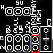
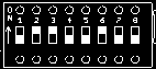
jumpers and switches on the JimStim? I think so, but I guess I don't really know where they're supposed to be. I know the switches are right, and I know the O2 is set on narrow band, but besides that I don't know. the pin labelled "2nd trigger" is jumped to the pin labelled "I1A (25)"

The three-pin row labelled "Primary tach" has the left two jumpered, and the two right next to it appear to both be jumped to the 5V pull up. That looks like it for jumpers.
Old Feb 10, 2011 | 08:36 AM
  #36  
Braineack's Avatar
Boost Czar
iTrader: (62)
 
Joined: May 2005
Posts: 80,552
Total Cats: 4,368
From: Chantilly, VA
Default

you need to do this:


shouldn't need any pull up jumpers.

and also this:


2nd trigger jumper should stay where it is.


It'll never sync if the rpm shows 65043. You must first clear the conflict error.
Old Feb 10, 2011 | 09:21 AM
  #37  
skidude's Avatar
Thread Starter
Elite Member
iTrader: (3)
 
Joined: Apr 2008
Posts: 2,023
Total Cats: 19
From: Outside Portland Maine
Default

Cleared the conflict error last night, so now rpm works. I will remove the pull up jumpers after work today and report back on the other pots.
Old Feb 10, 2011 | 10:01 AM
  #38  
richyvrlimited's Avatar
Elite Member
iTrader: (1)
 
Joined: Jun 2006
Posts: 2,642
Total Cats: 42
From: Warrington/Birmingham
Default

Randomly mine doesn't work unless I have pullup jumpers in place.

Works fine on the car (and has done for years).

So don't discount needing the pullups.
Old Feb 10, 2011 | 01:29 PM
  #39  
NiklasFalk's Avatar
Senior Member
iTrader: (1)
 
Joined: Jun 2006
Posts: 1,391
Total Cats: 63
From: Sweden
Default

Originally Posted by skidude
Wow, I'm also intimidated by the alternator circuit. That seems like a lot of crap to fit in the proto area, not to mention I don't know how I'll fit 3 wires into those holes.
The MS2 proto area is a bit different than the one on the DIYPNP, but maybe my layout can give some fresh ideas (if needed). It works (but I had a variable power supply and a bread board to verify everything before I started cramming everything into the proto area).
Old Feb 10, 2011 | 01:35 PM
  #40  
Braineack's Avatar
Boost Czar
iTrader: (62)
 
Joined: May 2005
Posts: 80,552
Total Cats: 4,368
From: Chantilly, VA
Default

Finally someone posts a diagram that makes logical sense to me.

Thread Tools
Search this Thread

All times are GMT -4. The time now is 01:07 PM.