
MS3 PnP build


Senior Member
Joined: Dec 2004
Posts: 1,278
Total Cats: 37
From: Brisbane, Australia
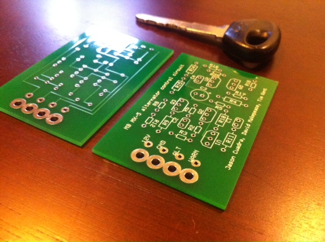
After getting permission from Jason I have had a PCB printed for the alternator control circuit incorporating the dash light driver. If anyone is interested, when I receive them I'll post up some pics.
Reply
 0
0

0
the output of the known working alternator circuit that goes to the field coil to the place in the above where it says +12 and the output of the above to the field coil and then set the output to only be enabled for over 450 rpm so it doesn't charge during cranking and make your belt squeal for 20 seconds every time you start your car.
Reply
0
0

Thread Starter
Senior Member
Joined: Nov 2007
Posts: 999
Total Cats: 73
From: Belgium
Reply
0
0

Well I'm interested (and also in purchasing one if it becomes available)
Reply
0
0

Joined: Jun 2005
Posts: 19,338
Total Cats: 574
From: Fake Virginia
And as a bonus, when the engine tries to stall, it doesn't die as easily.
Reply
0
0


Senior Member
Joined: Dec 2004
Posts: 1,278
Total Cats: 37
From: Brisbane, Australia
Let me populate one to make sure it works first. I like the idea of changing the footprint to suit a MegaSquirt case. The trim pot and axial cap changes could be implemented too.
These ones I have now (assuming they work alright) will be good for chucking in a small plastic sealed hobby box and using for any aftermarket ECU. I'm planning to use one with the Adaptronic in my track pig.
Jason should take the credit for this as it is his circuit. All David and I have done is lay it out so it looks pretty.
Reply
0
0

Thread
Thread Starter
Forum
Replies
Last Post
Zaphod
MEGAsquirt
47
Oct 26, 2018 11:00 PM


