
MS3X 100% idle duty cycle


Thread Starter
Senior Member
iTrader: (1)
Joined: Apr 2011
Posts: 1,332
Total Cats: 87
From: Columbia, SC
1. the idle is just messed up. why, i dunno. A fully opened idle valve should shoot the idle to around 3000RPM. I don't think it's software related though.
2. messed up your wiring or settings.
3. tune your cam zero-point pot (should have been turned at least 3 full turns CW)
2. messed up your wiring or settings.
3. tune your cam zero-point pot (should have been turned at least 3 full turns CW)
2: I'll double check it.
3: I'll turn it 3 turns clockwise and see if that fixes it.
Reply
 0
0

0

The latest FW has an initial duty table for the idles valve setting. X-Axis is rpms and Y-Axis seems to be coolant temp. Values are idle valve duty. This is where your FW looks up your initial setting for the idle valve PWM when the TPS goes to 0%. Set that to the value that's usually needed at a certain temp to reach your target rpm for that temp.
Are you sure 511Hz is a good frequency for the idle valve? I believe I'm running 75Hz and that seems to work very well.
Are you sure 511Hz is a good frequency for the idle valve? I believe I'm running 75Hz and that seems to work very well.
Reply
0
0
Thread Starter
Senior Member
iTrader: (1)
Joined: Apr 2011
Posts: 1,332
Total Cats: 87
From: Columbia, SC
The latest FW has an initial duty table for the idles valve setting. X-Axis is rpms and Y-Axis seems to be coolant temp. Values are idle valve duty. This is where your FW looks up your initial setting for the idle valve PWM when the TPS goes to 0%. Set that to the value that's usually needed at a certain temp to reach your target rpm for that temp.
Are you sure 511Hz is a good frequency for the idle valve? I believe I'm running 75Hz and that seems to work very well.
Are you sure 511Hz is a good frequency for the idle valve? I believe I'm running 75Hz and that seems to work very well.
https://www.miataturbo.net/megasquir...control-54877/
The main issue I'm still confused about though, is the fact that at different times it is taking different duty percentages to reach the same idle goal. That doesn't make sense.
Last edited by Schuyler; Jun 25, 2014 at 04:09 PM.
Reply
0
0
Thread Starter
Senior Member
iTrader: (1)
Joined: Apr 2011
Posts: 1,332
Total Cats: 87
From: Columbia, SC
EDIT: 7 turns CW on the main board pot made the car not crank.
EDIT EDIT: Video of the issue -
Last edited by Schuyler; Jun 25, 2014 at 07:26 PM.
Reply
0
0


Thread Starter
Senior Member
iTrader: (1)
Joined: Apr 2011
Posts: 1,332
Total Cats: 87
From: Columbia, SC
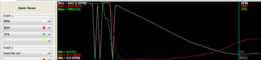
Log pic:
Reply
0
0
Thread Starter
Senior Member
iTrader: (1)
Joined: Apr 2011
Posts: 1,332
Total Cats: 87
From: Columbia, SC
The signal I'm losing is the green line. Fiddling with the pots seems to have given me a few hundred extra rpm. I had reset the main board pots, but left the three added turns on the expansion r11. Which pot would have influenced this signal?
(No WiFi to post composite log)
(No WiFi to post composite log)
Reply
0
0
Thread Starter
Senior Member
iTrader: (1)
Joined: Apr 2011
Posts: 1,332
Total Cats: 87
From: Columbia, SC
I've fixed it. I honestly just played with the pots on the expansion board, revving the car up every few turns until it worked. Now to figure out my idle and get rid of these WOT lean spots.
Reply
0
0
Yes 511 Hz
Idle PWM % will very for the same RPM due to the mass of variables involved in idle, including Alt load, temp, and things beyond me. So hence the need for closed loop to alter the valve setting to maintain idle.
I prefer to "Use initial value table" rather than "last value"
Suggest you use CLT, not MAT for the idle speed set point from value table.
Reply
0
0
Thread Starter
Senior Member
iTrader: (1)
Joined: Apr 2011
Posts: 1,332
Total Cats: 87
From: Columbia, SC
Good Deal
Yes 511 Hz
Idle PWM % will very for the same RPM due to the mass of variables involved in idle, including Alt load, temp, and things beyond me. So hence the need for closed loop to alter the valve setting to maintain idle.
I prefer to "Use initial value table" rather than "last value"
Suggest you use CLT, not MAT for the idle speed set point from value table.
Reply
0
0

Certainly forcing the idle up with the screw will be a good test for that. As you say, if it will not go back down, then that is a good data point.
Is it possible to idle on screw opening alone (pulling the connector from the control valve). Can that be used as a maximum screw opening at, say 700 RPM?
Yeah, like mine runs 650 RPM with valve closed.
Reply
0
0
Thread Starter
Senior Member
iTrader: (1)
Joined: Apr 2011
Posts: 1,332
Total Cats: 87
From: Columbia, SC
So you're thinking that the MS is saying it is delivering 100%, but that the valve is not really opening 100%?
Certainly forcing the idle up with the screw will be a good test for that. As you say, if it will not go back down, then that is a good data point.
Is it possible to idle on screw opening alone (pulling the connector from the control valve). Can that be used as a maximum screw opening at, say 700 RPM?
Yeah, like mine runs 650 RPM with valve closed.
Reply
0
0


