MTX-L Ground/12V Noise PSA
 04-08-2013, 11:14 PM
#1

DIYPNP, NA 94 Miata.
I was having serious battery voltage/afr noise when I had GND/12V hooked up via the DB15 to ECU GND/12V.
Rewiring it to the cigarette lighter GND/12V fixed the issue. After some research, it seems that the heater PWM circuit was the cause of the noise.
Before: .4V fluctuation @ lag = 50
After: .1V fluctuation @ lag = 90
This seems to be a shortcoming of the MTX-L wideband. The voltage->afr calibration numbers did not seem to need to change.

Reply
 0
0

0
 04-15-2013, 09:07 AM
#4
Junior Member

Join Date: Nov 2010
Location: London, UK
Posts: 102
Total Cats: 0
IIRC other connections for the MTX-L are the WB output, NB Simulated output and Lighting circuit feed (Dial dimmer)
Most threads on here general for WB and don't obviously translate to the MTX-L. As far as I can see it there seems to be two schools of thought:
1.
- Power from pretty much any Ignition switched +12V.
- Ground to the same spot on the head as ECU Ground feed (Stud by Throttle Body), via a dedicated wire for the WB.
2.
- Route both live and ground into Megasquirt, jumper across internally to the ECU live and ground feeds. Whilst some seem to dislike this, I believe it it is how Reverent does his ECUs.
Plus of course a myriad of other options including grounding to Chassis anywhere behind Dash, tapping into Cigarette Lighter, Stereo etc.
I have currently routed my MTX-L live and ground through the MS DIYPNP as you did previously. Following this and other threads I will likely put in-line bullet connectors on the DB tails so I can change options easily without it getting messy.
The only query I had with this, which possibly relates to this thread, is whether or not it matters which Ground in the DIYPNP to jumper to internally. I saw in one thread a suggestion that the Sensor Ground should be avoided. If this the reason why a few people may have had issues with running the WB all though the ECU? For some reason I thought that the DIYPNP has all the grounds connected internally anyway so it wouldn't make a difference.
Any thoughts?
Dave
Last edited by ManicGTI; 04-15-2013 at 09:20 AM.
Reply
0
0
04-15-2013, 06:04 PM
#7
Elite Member

Join Date: Jul 2005
Posts: 6,420
Total Cats: 84
The heater current will produce a voltage drop along the wire that goes from the POWER GND pin to the engine block. This is not a problem as long as the engine sensors have a dedicated ground wire going to the SENSOR GND pin on the ECU. You WILL have a problem if you have a 2nd connection from a sensor's ground to the engine block.
Reply
0
0
05-04-2013, 03:30 PM
#8
Senior Member

Join Date: Nov 2007
Location: Belgium
Posts: 999
Total Cats: 73
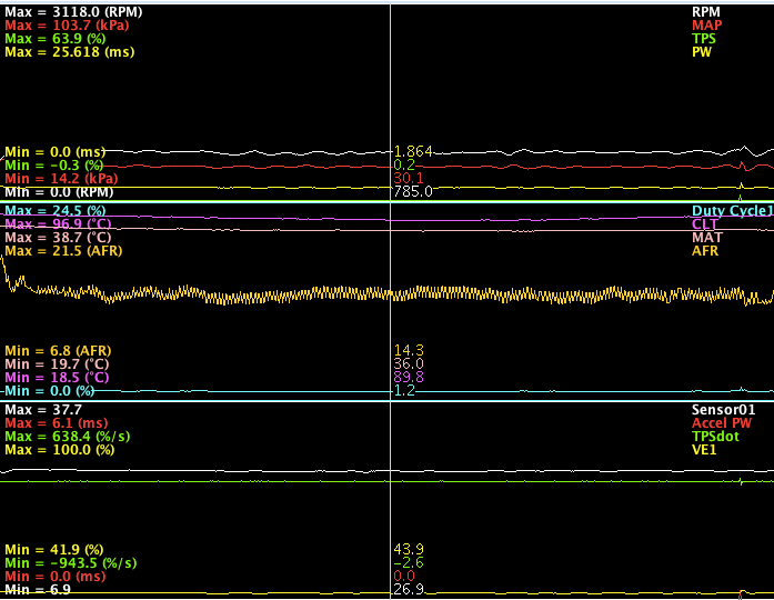
I installed ABS and COPS on my car a couple of weeks ago and in the process rewired my entire engine harness. I never had AFR noise before but I decided to rewire the MTX-L as well. I can't remember how it was connected before but I moved 12V and GND to the MS.
This was the result
10x zoom:
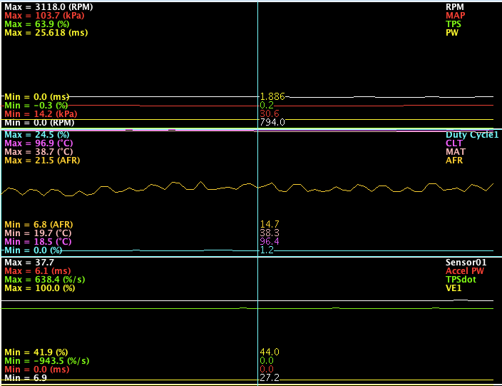
1x zoom:
I moved the gnd point to various places all over the car (rear of engine, front of engine, steering column, cigarette lighter, bare chassis, MS case etc etc) trying to get rid of the noise.
I also measured the voltage drops between the MS ground and the other grounds. I found up to 90mV offset.
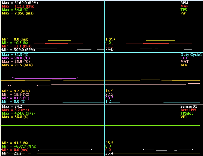
In the end, I took gnd via a seperate wire to the back of the engine. This resulted in about 9mV offset. I then ran a gnd wire from the steering column to the MS mounting bracket which further reduced it to 2-3mV.
Quite happy with the result:
1x zoom:
This was the result
10x zoom:
1x zoom:
I moved the gnd point to various places all over the car (rear of engine, front of engine, steering column, cigarette lighter, bare chassis, MS case etc etc) trying to get rid of the noise.
I also measured the voltage drops between the MS ground and the other grounds. I found up to 90mV offset.
In the end, I took gnd via a seperate wire to the back of the engine. This resulted in about 9mV offset. I then ran a gnd wire from the steering column to the MS mounting bracket which further reduced it to 2-3mV.
Quite happy with the result:
1x zoom:
Last edited by WestfieldMX5; 05-04-2013 at 04:14 PM. Reason: to add that Lambda averaging lag factor is set at 90
Reply
0
0
 05-05-2013, 05:23 AM
#10
Senior Member
Join Date: Nov 2007
Location: Belgium
Posts: 999
Total Cats: 73
I never tested it but since the heatsink touches the case, I'm sure the MS is grounded as well through the case. There's at least a couple of transistors that don't need a mica and have gnd on their mouting tab. A metal tab version of U5 comes to mind.
Reply
0
0
05-06-2013, 06:32 AM
#12
Senior Member
Join Date: Nov 2007
Location: Belgium
Posts: 999
Total Cats: 73
yes, the MTX-L gnd. I took a long gnd wire and tried different spots throughout the car until I had the least noise. Actually I used 2 wires. It takes like 15s for the MTX-L to startup, so I made sure to connect the 2nd gnd before disconnecting the 1st one. That way the wb stayed powered up all the time, saving a lot of time.
I know the extra steering column gnd doesn't make sense, but it cured my noise completely so I'm quite happy.
I know the extra steering column gnd doesn't make sense, but it cured my noise completely so I'm quite happy.
Reply
0
0
05-06-2013, 10:23 AM
#13
Elite Member
Join Date: Jul 2005
Posts: 6,420
Total Cats: 84
Your result suggests to me that the PCB routing of the grounds in the MS2(?) are unconventional.
Where did you place the voltmeter probes while doing this test?
I also measured the voltage drops between the MS ground and the other grounds
Reply
0
0
05-06-2013, 10:37 AM
#14

It seems the MTX-L is very prone to offset voltage issues. I've never gotten mine perfect and I've tried grounding on the frame, engine block, DIYPNP (tried several grounds internally) and I still have a slight offset between the MTX-L and Tunerstudio.
In LM Programmer, you can set the warmup voltage to whatever you want. I made a graph by setting the output in increments of .5 volts and measured the reading at the MS, and what Tunerstudio was reading. I always have a .06v - .08v difference between the MTX-L output setting, and actual voltage read at the MS. The only way I could get it to track properly was to adjust the Custom Linear Wideband setting to compensate.
Sure would be nice if these two played nicer together.
Reply
0
0
05-06-2013, 10:51 AM
#15
Elite Member
Join Date: Jul 2005
Posts: 6,420
Total Cats: 84
This is because Innovate decided to combine its 2 ground wires into one. Having a separate analog gnd, and heater gnd wire was good (see 4-wire O2 sensors), but I guess it confused too many customers.
Whenever troubleshooting ground offset issues, measure the voltage with the engine off, at the MTX-L's terminals (place voltmeter probes at output, and the end of its ground wire), and compare it against the ECU reading. Also measure the voltage at the ECU pins, (the WBO2 input pin, and the SGND pin).
Whenever troubleshooting ground offset issues, measure the voltage with the engine off, at the MTX-L's terminals (place voltmeter probes at output, and the end of its ground wire), and compare it against the ECU reading. Also measure the voltage at the ECU pins, (the WBO2 input pin, and the SGND pin).
Reply
0
0
05-06-2013, 11:43 AM
#17
Senior Member
Join Date: Nov 2007
Location: Belgium
Posts: 999
Total Cats: 73
I measured between the MS gnd right at the back of the connector, black/yellow (power gnd on a 99) and the MTX-L ground.
I shortened the MTX-L power wires to about the same length as the existing connector for the sensor (about 1.5ft) and installed a connector there to make removing the gauge easier.
Each time I moved the MTX-L ground to a different point and measured between MS connector and MTX-L connector that I added (thus about 1.5ft from the gauge).
Reply
0
0
05-06-2013, 11:51 AM
#18
Elite Member
Join Date: Jul 2005
Posts: 6,420
Total Cats: 84
All grounds that pass high current (e.g. injector, solenoid, O2 heaters), should go to the engine block. Inside the ECU, all high current returns should go to the PGND pin.
If using the LC-1 which has a separate heater ground and signal ground, then you connect the LC1 signal ground to the ECU signal ground, then the LC1 heater ground, to the engine block.
The MTX-L has a single ground wire. Connect it to the ECU power ground pin. This is a compromise. Connecting to the SGND pin will cause the MTX-L heater currents to contaminate the ground signal of *all* other sensors.
In making this recommendation I am assuming that inside the ECU there is a connection between PGND and SGND, near the ADC's, and that the connection from that point, to the PGND pin, is a low impedance. AEM Series 1 did not follow these guidelines, and when I hacked it to fix this, greatly reduced noise on the analog channels.
However, WestfieldMX5's experience does not support my contention; probably because the MS3 does not follow the internal rules I mentioned, OR, there is other information about his experimentation that I'm missing.
Reply
1
1


