Notices
MEGAsquirt A place to collectively sort out this megasquirt gizmo

Need Help Navigating TS and Uploading a Base Tune

Thread Tools
 
Search this Thread
 
Old Aug 1, 2013 | 10:22 AM
  #21  
lyodakin's Avatar
Thread Starter
Junior Member
iTrader: (1)
 
Joined: Jul 2013
Posts: 73
Total Cats: -8
Default

Originally Posted by Braineack
I'm looking for the post that says you've confirmed you were getting spark on all four cylinders but fuel on only 2 or vice versa...
I'm only getting spark on two. The MS is only driving one coil. I can swap the plugs at the coil and it flip flops which coil gets power.
Old Aug 1, 2013 | 10:28 AM
  #22  
Braineack's Avatar
Boost Czar
iTrader: (62)
 
Joined: May 2005
Posts: 80,552
Total Cats: 4,368
From: Chantilly, VA
Default

okay.

and you're wired to 4N and 4R?
Old Aug 1, 2013 | 10:34 AM
  #23  
lyodakin's Avatar
Thread Starter
Junior Member
iTrader: (1)
 
Joined: Jul 2013
Posts: 73
Total Cats: -8
Default

Originally Posted by Braineack
okay.

and you're wired to 4N and 4R?
Yes, I quintuple checked lol
Old Aug 1, 2013 | 11:20 AM
  #24  
lyodakin's Avatar
Thread Starter
Junior Member
iTrader: (1)
 
Joined: Jul 2013
Posts: 73
Total Cats: -8
Default

I believe this wiring to be correct for IG1 & 2. Am I wrong?


Attached Thumbnails Need Help Navigating TS and Uploading a Base Tune-ms-101_zps9883eb49.jpg   Need Help Navigating TS and Uploading a Base Tune-ms-102_zps8bc0430f.jpg  
Old Aug 1, 2013 | 03:19 PM
  #25  
lyodakin's Avatar
Thread Starter
Junior Member
iTrader: (1)
 
Joined: Jul 2013
Posts: 73
Total Cats: -8
Default

Any ideas or tests I can perform to figure out what the problem is?
Old Aug 1, 2013 | 03:31 PM
  #26  
Braineack's Avatar
Boost Czar
iTrader: (62)
 
Joined: May 2005
Posts: 80,552
Total Cats: 4,368
From: Chantilly, VA
Default

you're using a basemap for the diypnp and your project is setup for diypnp microsquirt, not megasquirt v3.0/v3.57?
Old Aug 1, 2013 | 03:42 PM
  #27  
lyodakin's Avatar
Thread Starter
Junior Member
iTrader: (1)
 
Joined: Jul 2013
Posts: 73
Total Cats: -8
Default

Originally Posted by Braineack
you're using a basemap for the diypnp and your project is setup for diypnp microsquirt, not megasquirt v3.0/v3.57?
I'll check again but yes, I believe the properties are setup correctly.

DIYPNP MegaSquirt installation for the Mazda Miata

Using the basemap right from that page.
Old Aug 1, 2013 | 04:40 PM
  #28  
lyodakin's Avatar
Thread Starter
Junior Member
iTrader: (1)
 
Joined: Jul 2013
Posts: 73
Total Cats: -8
Default

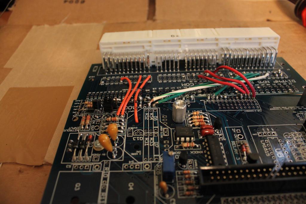
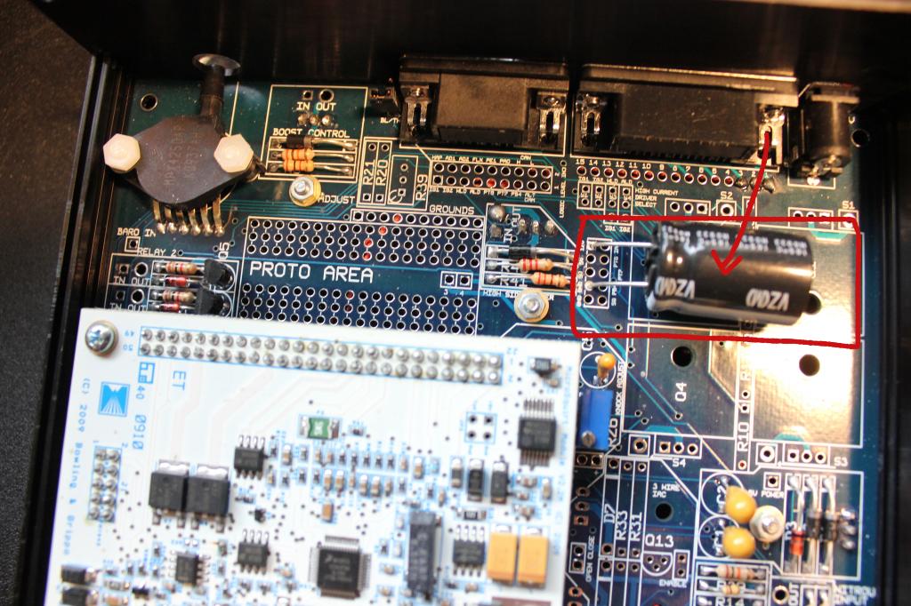
Ok so I obviously I didn't assemble my board and I cannot find any assembly guide for my board. But after looking at images I cant figure out for the life of me what this is. and why I don't have any resistors going down the ignition portion of the board.

Attached Thumbnails Need Help Navigating TS and Uploading a Base Tune-megaa_zpsc16bbe60.jpg  
Old Aug 1, 2013 | 04:59 PM
  #29  
Braineack's Avatar
Boost Czar
iTrader: (62)
 
Joined: May 2005
Posts: 80,552
Total Cats: 4,368
From: Chantilly, VA
Default

it's a capacitor working as a noise filter.

because you dont need resistors.
Old Aug 1, 2013 | 05:04 PM
  #30  
lyodakin's Avatar
Thread Starter
Junior Member
iTrader: (1)
 
Joined: Jul 2013
Posts: 73
Total Cats: -8
Default

Originally Posted by Braineack
it's a capacitor working as a noise filter.

because you dont need resistors.
Ah ok.

TS is properly set to DIYPNP.
Old Aug 2, 2013 | 02:43 AM
  #31  
lyodakin's Avatar
Thread Starter
Junior Member
iTrader: (1)
 
Joined: Jul 2013
Posts: 73
Total Cats: -8
Default

Grr no luck this evening. Tried to re-solder the IG1 & 2 wires and even tried a new location on the board.

Would converting to COP bypass this issue?
Old Aug 2, 2013 | 07:03 AM
  #32  
Braineack's Avatar
Boost Czar
iTrader: (62)
 
Joined: May 2005
Posts: 80,552
Total Cats: 4,368
From: Chantilly, VA
Default

no.

you need to figure out why it's not firing one of the two channels. Could be a bad solder joint between the ECU and IGN1 or IGN2?
Old Aug 2, 2013 | 04:34 PM
  #33  
lyodakin's Avatar
Thread Starter
Junior Member
iTrader: (1)
 
Joined: Jul 2013
Posts: 73
Total Cats: -8
Default

Originally Posted by Braineack
no.

you need to figure out why it's not firing one of the two channels. Could be a bad solder joint between the ECU and IGN1 or IGN2?

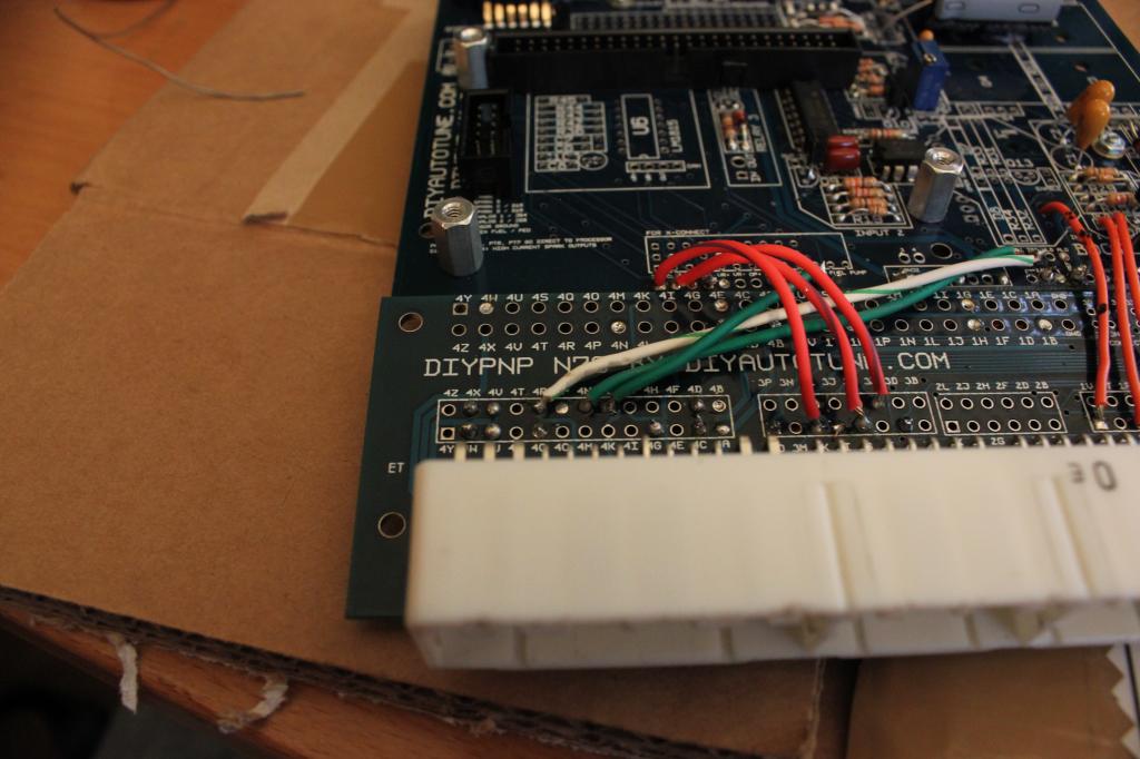
I honestly don't know where to start when checking bad solder joints. I tried re-locating IG1 & 2 on the board, no difference was made.
Old Aug 6, 2013 | 03:26 PM
  #34  
lyodakin's Avatar
Thread Starter
Junior Member
iTrader: (1)
 
Joined: Jul 2013
Posts: 73
Total Cats: -8
Default

How do I go about testing for a bad ignition transistor?
Old Aug 6, 2013 | 03:31 PM
  #35  
Braineack's Avatar
Boost Czar
iTrader: (62)
 
Joined: May 2005
Posts: 80,552
Total Cats: 4,368
From: Chantilly, VA
Default

the spark output comes directly from the CPU IIRC.

review the schematics.

Microsquirt-module - board schematics
Old Aug 6, 2013 | 03:48 PM
  #36  
lyodakin's Avatar
Thread Starter
Junior Member
iTrader: (1)
 
Joined: Jul 2013
Posts: 73
Total Cats: -8
Default

ok got it. Do i need a stim to test the functionality of IG2?
Old Aug 6, 2013 | 04:37 PM
  #37  
Braineack's Avatar
Boost Czar
iTrader: (62)
 
Joined: May 2005
Posts: 80,552
Total Cats: 4,368
From: Chantilly, VA
Default

that would be most helpful. but i'd make sure that your inputs make it all the way back to the CPU first.
Old Aug 6, 2013 | 05:00 PM
  #38  
lyodakin's Avatar
Thread Starter
Junior Member
iTrader: (1)
 
Joined: Jul 2013
Posts: 73
Total Cats: -8
Default

Originally Posted by Braineack
that would be most helpful. but i'd make sure that your inputs make it all the way back to the CPU first.
Yes, I want to do that but I cant find any material on how to perform that test.
Any information would be greatly appreciated.
Old Sep 16, 2013 | 04:37 PM
  #39  
lyodakin's Avatar
Thread Starter
Junior Member
iTrader: (1)
 
Joined: Jul 2013
Posts: 73
Total Cats: -8
Default

Does anyone offer a repair service?
Old Sep 16, 2013 | 05:50 PM
  #40  
bahurd's Avatar
Elite Member
iTrader: (8)
 
Joined: Apr 2013
Posts: 2,408
Total Cats: 316
Default

Originally Posted by lyodakin

Yes, I want to do that but I cant find any material on how to perform that test.
Any information would be greatly appreciated.
Wouldn't you just check for continuity on the circuit with a meter? Sorry if I'm over simplifying it.
Related Topics
Thread
Thread Starter
Forum
Replies
Last Post
LucaCarMods
Build Threads
11
Feb 14, 2016 06:13 AM
tazswing
Race Prep
20
Oct 3, 2015 11:04 AM
The Gleas
MEGAsquirt
3
Oct 1, 2015 09:30 AM
FrankB
Miata parts for sale/trade
6
Sep 30, 2015 11:48 AM
brandonbkd
MEGAsquirt
0
Sep 28, 2015 11:52 PM


All times are GMT -4. The time now is 08:51 AM.