
Oochi's MS3X DIY Build


Thread Starter
Junior Member
Joined: May 2011
Posts: 221
Total Cats: 1
From: Central Kentucky
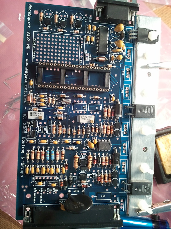
So this is what I am looking at now. I still have to decide on the U3 U7 dilemma but idk which is better, easier. More reading will come. But other than that and the map sensor thing on the bottom, that looks like pretty much everything right?
Reply
 0
0

0


Joined: Sep 2005
Posts: 34,422
Total Cats: 7,542
From: Chicago. (The less-murder part.)
You don't need the two large resistors on the heatsink, either. They're part of the fuel injector circuit you're not using.
You do need either U3 or U7, depending on which circuit you use for the crank input. I suggest that you install U7 and run jumpers from "TachSelect" to "VrIn" and from "VrOut" to "Tsel". (Don't forget to adjust R56 for ~2.5v at R54, and turn R52 to about one full turn clockwise from fully counterclockwise. This will create some hardware latency that you'll need to correct for in software.) I believe that you'll also need a pullup resistor from 5v to the side of R45 which is towards VrIn.
You can go ahead and install the three LEDs. They're kind of pretty.
Nice job of soldering, by the way. It looks very clean.
Reply
0
0
Thread Starter
Junior Member
Joined: May 2011
Posts: 221
Total Cats: 1
From: Central Kentucky
Thanks Joe, it's my second time soldering, and I have a $5 harbor freight iron lol. I'll take the two resistors off of the heatsink this weekend and install the U7 stuff. And how do I go about adjusting R56 for ~2.5v at R54 for sure?
Reply
0
0
Joined: Sep 2005
Posts: 34,422
Total Cats: 7,542
From: Chicago. (The less-murder part.)
Just turn it with a screwdriver while probing between R54 and GND with a voltmeter.
You'll need to do the same on the MS3X board for the cam input, though I don't have the schematic here in front of me and so I can't remember exactly which resistor it is.
Basically, you're just setting the trigger threshold for detecting the cam and crank sensors. They swing from appx 0-5v, so we're setting it in the middle. It's not important to be exact here, anything in the neighborhood of 2-3 volts will be sufficient.
Reply
0
0

At this point I'd use the VR circuit, so you need U7. That means you dont need: d1, d2, c30, c12, u3, r13, and c11... get it? but you have some of them installed.
Our writeup and diagrams were to try to prevent these useless components to be installed.
for example: your ms3x card will take care of the spark and fuel circuits, so you dont need to build them into the mainboard.
Most things should end ultimately end up on the expander card, like your idle, ebc, fuel & spark, cam input, etc.
The only real difference between my component map, is that I am utilzing the opto circuit for the crnak input, where Frank's is setup to use the VR circuit.
I'd suggest going to megamanual.com, and clicking on v3 DIY mainboard, and it shows exactly where component resides and in what circuit is it for. There's a method to the madness.
Reply
0
0
Thread Starter
Junior Member
Joined: May 2011
Posts: 221
Total Cats: 1
From: Central Kentucky
Originally Posted by Joe Perez
ust turn it with a screwdriver while probing between R54 and GND with a voltmeter.
You'll need to do the same on the MS3X board for the cam input, though I don't have the schematic here in front of me and so I can't remember exactly which resistor it is.
Basically, you're just setting the trigger threshold for detecting the cam and crank sensors. They swing from appx 0-5v, so we're setting it in the middle. It's not important to be exact here, anything in the neighborhood of 2-3 volts will be sufficient.
Originally Posted by WestfieldMX5
You're clearly not listening to the advice given here.
You're clearly not reading the manuals, so I'm not going to bother
You're clearly not reading the manuals, so I'm not going to bother
Originally Posted by Braineack
uhhhhh... what dilemma, I mean you've populated the entire board, might as well populate those too. U3 is required to use the opto circuit and has about 6 other components needed in conjunction with it, all look populated. U7 is for the VR circuit and has about 20 other components needed in conjunction with it, all look populated. So I mean, install them both...and pick which circuit you want to use...
At this point I'd use the VR circuit, so you need U7. That means you dont need: d1, d2, c30, c12, u3, r13, and c11... get it? but you have some of them installed.
Our writeup and diagrams were to try to prevent these useless components to be installed.
for example: your ms3x card will take care of the spark and fuel circuits, so you dont need to build them into the mainboard.
Most things should end ultimately end up on the expander card, like your idle, ebc, fuel & spark, cam input, etc.
The only real difference between my component map, is that I am utilzing the opto circuit for the crnak input, where Frank's is setup to use the VR circuit.
I'd suggest going to megamanual.com, and clicking on v3 DIY mainboard, and it shows exactly where component resides and in what circuit is it for. There's a method to the madness.
 ness
ness
Reply
0
0
Thread Starter
Junior Member
Joined: May 2011
Posts: 221
Total Cats: 1
From: Central Kentucky
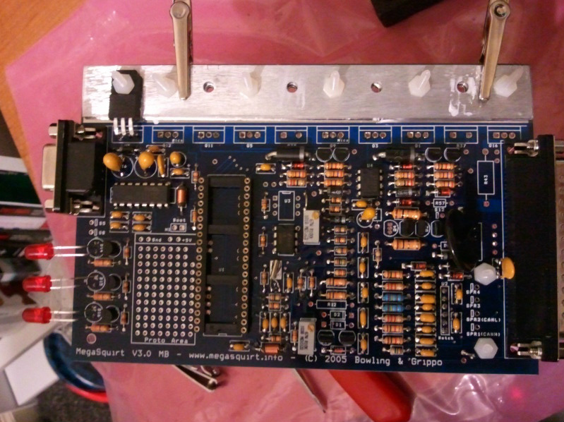
OK, quick update. I finally got to work on it a little more. Removed the 2 resistors on the heatsink that i shouldn't have installed (among many other things I shouldn't have installed), installed the map sensor, completed the U7 circuit. Now I still have to adjust R56, jump S12C to JS9, look into making the harness, which ms3x wires I need and which I don't. And installing the daughter board and expander. I Also received my 64 pin connector from mouser electronics ($20 shipped).
Reply
0
0
Thread Starter
Junior Member
Joined: May 2011
Posts: 221
Total Cats: 1
From: Central Kentucky
Question on this, I have spare 1k ohm resistors i was going to use one as described in westfield's guide, but mine is 1/2W. May be a dumb question but I just wanted to make sure.
Reply
0
0

Junior Member
Joined: Mar 2011
Posts: 163
Total Cats: 0
From: Guildford, UK

Reply
0
0

Senior Member
Joined: Nov 2007
Posts: 999
Total Cats: 73
From: Belgium
For the main board, measure the voltage between R54 and pin 3 of U7 while turning R56. On the MS3X board, measure between R17 and pin 3 of U7 while turning R11. In both cases, you want to see about 2.5 to 3 volts at that point, which puts you right in the middle of the actual output range of the sensors.
Reply
0
0
Junior Member
Joined: Mar 2011
Posts: 163
Total Cats: 0
From: Guildford, UK
For the main board, measure the voltage between R54 and pin 3 of U7 while turning R56. On the MS3X board, measure between R17 and pin 3 of U7 while turning R11. In both cases, you want to see about 2.5 to 3 volts at that point, which puts you right in the middle of the actual output range of the sensors.

Reply
0
0
Thread Starter
Junior Member
Joined: May 2011
Posts: 221
Total Cats: 1
From: Central Kentucky
In my case, the harness should look like this, right?
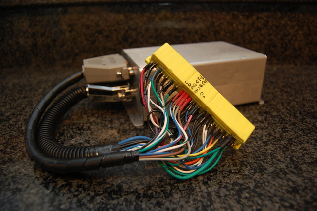
Edit: On this pinout, I bought the 64 pin connector, but this diagram is for the 48 pin. I would assume I just leave the middle section out and just fill in the outer two sections according to the diagram? Also, How do I know what is needed out of the mainboard and what is needed out of the expander card? Thanks for help. I have attempted searching, but haven't found anything regarding ms3x

Edit: On this pinout, I bought the 64 pin connector, but this diagram is for the 48 pin. I would assume I just leave the middle section out and just fill in the outer two sections according to the diagram? Also, How do I know what is needed out of the mainboard and what is needed out of the expander card? Thanks for help. I have attempted searching, but haven't found anything regarding ms3x
Last edited by Oochi; Feb 23, 2012 at 11:41 PM.
Reply
0
0
Junior Member
Joined: Mar 2011
Posts: 163
Total Cats: 0
From: Guildford, UK
Here ya go.
http://www.msextra.com/doc/ms3/hardware.html#wiring
Write a list, start with everything that is definitely connected to the 3X, injection, cam, idle, spark, etc
Everything else from the V3 board, IAT, coolant fuel pump, o2
http://www.msextra.com/doc/ms3/hardware.html#wiring
Write a list, start with everything that is definitely connected to the 3X, injection, cam, idle, spark, etc
Everything else from the V3 board, IAT, coolant fuel pump, o2
Reply
0
0

Junior Member
Joined: Mar 2010
Posts: 413
Total Cats: 2
From: onion city,ca
having just finished my first ms3 w/ ms3x i can attest to the fact that it is hella confusing for a noob on what components are required and also what components go with what mods. I ended up soldering in most of the stuff even though i'm using the expander but i still managed to leave out q22 and q23 so my crank input didn't work. duh.
people here have been saying to check out megamanual for schematics etc, but i found the msextra schematics very useful when checking my VR input (crank) stuff. towards bottom of this page: http://www.msextra.com/doc/index.html
Definitely stim that thing. the stim is awesome as a confidence booster. you can twiddle all the inputs and see them move on tunerstudio.
i'd also recommend using the usb connector on the cpu board. works perfectly for me. also worth mentioning that if you have any can bus devices you will need to run 2 wires to connect them up to the db37 (in my case my dash is can connected).
edit: ms3x connector is listed on the link i gave above. or here if you are lazy:: http://www.msextra.com/doc/ms3/hardw...ml#wiring-ms3x
Reply
0
0
Thread Starter
Junior Member
Joined: May 2011
Posts: 221
Total Cats: 1
From: Central Kentucky
Thanks for all the help freaky!
Interested! Do you have pictures of it completed? What year is your car? And would you be willing to part with the stim?
On a different topic, I need to reassure this: In step 22 of westfield's guide it says
Step 22: install a jumper from S12C to JS9. Ignore the rest of the instructions in this step
But in the megamanual, it states that:
DO NOT INSTALL THIS JUMPER FOR NON-MegaSquirt-II APPLICATIONS - IT WILL DESTROY THE PROCESSOR!!
I would think this isn't a problem since nobody has said anything about it and it is in fact in westfield's guide.
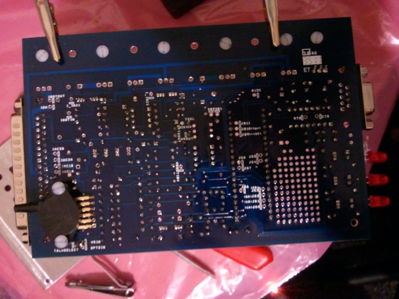
Also with the 90-93 fuel pump circuit, referring to this picture:
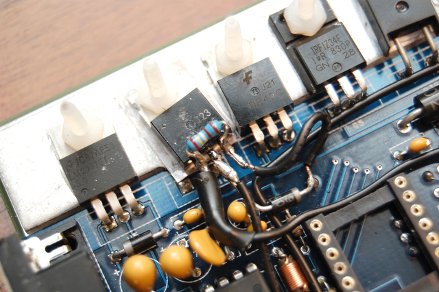
the 3rd lead on the transistor is connected to the same spot as that jumper that I just mentioned above. Would it be reccomended to connect both the jumper and the fuel pump circuit to that spot? And if Anyone has any other pictures of their fuel pump mod, i would appreciate seeing those. but other than that mod, there really isnt any other mods I need to worry about right? Not keeping ac
having just finished my first ms3 w/ ms3x i can attest to the fact that it is hella confusing for a noob on what components are required and also what components go with what mods. I ended up soldering in most of the stuff even though i'm using the expander but i still managed to leave out q22 and q23 so my crank input didn't work. duh.
people here have been saying to check out megamanual for schematics etc, but i found the msextra schematics very useful when checking my VR input (crank) stuff. towards bottom of this page: http://www.msextra.com/doc/index.html
Definitely stim that thing. the stim is awesome as a confidence booster. you can twiddle all the inputs and see them move on tunerstudio.
i'd also recommend using the usb connector on the cpu board. works perfectly for me. also worth mentioning that if you have any can bus devices you will need to run 2 wires to connect them up to the db37 (in my case my dash is can connected).
edit: ms3x connector is listed on the link i gave above. or here if you are lazy:: http://www.msextra.com/doc/ms3/hardw...ml#wiring-ms3x
people here have been saying to check out megamanual for schematics etc, but i found the msextra schematics very useful when checking my VR input (crank) stuff. towards bottom of this page: http://www.msextra.com/doc/index.html
Definitely stim that thing. the stim is awesome as a confidence booster. you can twiddle all the inputs and see them move on tunerstudio.
i'd also recommend using the usb connector on the cpu board. works perfectly for me. also worth mentioning that if you have any can bus devices you will need to run 2 wires to connect them up to the db37 (in my case my dash is can connected).
edit: ms3x connector is listed on the link i gave above. or here if you are lazy:: http://www.msextra.com/doc/ms3/hardw...ml#wiring-ms3x
On a different topic, I need to reassure this: In step 22 of westfield's guide it says
Step 22: install a jumper from S12C to JS9. Ignore the rest of the instructions in this step
But in the megamanual, it states that:
DO NOT INSTALL THIS JUMPER FOR NON-MegaSquirt-II APPLICATIONS - IT WILL DESTROY THE PROCESSOR!!
I would think this isn't a problem since nobody has said anything about it and it is in fact in westfield's guide.
Also with the 90-93 fuel pump circuit, referring to this picture:
the 3rd lead on the transistor is connected to the same spot as that jumper that I just mentioned above. Would it be reccomended to connect both the jumper and the fuel pump circuit to that spot? And if Anyone has any other pictures of their fuel pump mod, i would appreciate seeing those. but other than that mod, there really isnt any other mods I need to worry about right? Not keeping ac
Last edited by Oochi; Feb 28, 2012 at 11:56 PM.
Reply
0
0
Junior Member
Joined: Mar 2010
Posts: 413
Total Cats: 2
From: onion city,ca
i'll send you my stim and power supply if you will return it when you are done. its worth noting that both of us are using ms3x which means the stim doesn't see those outputs. it can generate all of the standard inputs though (crank/clt/o2/mat/tps/etc).
Reply
0
0


