MEGAsquirt A place to collectively sort out this megasquirt gizmo

Second optoisolator on MS2

Thread Tools
 
Search this Thread
 
Old 03-05-2013, 08:06 AM
  #41  
Senior Member
 
WestfieldMX5's Avatar
 
Join Date: Nov 2007
Location: Belgium
Posts: 999
Total Cats: 73
Default

2nd opto .
I just seem to remember that you use both stock input circuits (VR and Opto). Not sure though, I seem to have developed 'youth alzheimer' .
WestfieldMX5 is offline  
Old 03-05-2013, 09:45 AM
  #42  
Ben
Supporting Vendor
iTrader: (33)
 
Ben's Avatar
 
Join Date: Jul 2006
Location: atlanta-ish
Posts: 12,659
Total Cats: 134
Default

Originally Posted by WestfieldMX5
2nd opto .
I just seem to remember that you use both stock input circuits (VR and Opto). Not sure though, I seem to have developed 'youth alzheimer' .
I've set them up using the mainboard VR conditioner for CKP input and the mainboard opto input for CMP input. That works well, too.
__________________
Chief of Floor Sweeping, DIYAutoTune.com & AMP EFI
Crew Chief, Car Owner & Least Valuable Driver, HongNorrthRacing

91 Turbo | 10AE Turbo | 01 Track Rat | #323 Mazda Champcar

Originally Posted by concealer404
Buy an MSPNP Pro, you'll feel better.
Ben is offline  
Old 03-15-2013, 09:05 AM
  #43  
Junior Member
Thread Starter
iTrader: (1)
 
duffbuster243's Avatar
 
Join Date: Sep 2010
Location: Scranton PA
Posts: 264
Total Cats: 4
Default

I'm going to try the 2nd optoisolator and I am ordering the parts now. Please make sure these parts number are appropriate for my needs:

Index Quantity Part Number Description Customer Reference Available Quantity Backorder Quantity Unit Price Extended Price
1 2 4N25VS-ND OPTOCOUPLER PHOTOTRANS 20% 6DIP 2
Immediate 0 0.57000 $1.14
2 5 470QBK-ND RES 470 OHM 1/4W 5% CARBON FILM 5
Immediate 0 0.10000 $0.50
3 5 4.7KQBK-ND RES 4.7K OHM 1/4W 5% CARBON FILM 5
Immediate 0 0.10000 $0.50
4 5 1.0KQBK-ND RES 1.0K OHM 1/4W 5% CARBON FILM 5
Immediate 0 0.10000 $0.50


I also need the 0.01 uF Capacitor, what is a good digikey part number for this?

I'm ordering some extras as I may also do this for a friend that is having the same issues with his MS1.
duffbuster243 is offline  
Old 03-15-2013, 09:15 AM
  #44  
Boost Czar
iTrader: (62)
 
Braineack's Avatar
 
Join Date: May 2005
Location: Chantilly, VA
Posts: 79,501
Total Cats: 4,080
Default

399-4326-nd
Braineack is offline  
Old 03-15-2013, 09:24 AM
  #45  
Junior Member
Thread Starter
iTrader: (1)
 
duffbuster243's Avatar
 
Join Date: Sep 2010
Location: Scranton PA
Posts: 264
Total Cats: 4
Default

Originally Posted by Braineack
399-4326-nd
Great, Thanks! I'll post again if I'm successful, Probably won't be for a few weeks as I have my cracking weekly ebay manifold off getting duplicated by a professional welder.
duffbuster243 is offline  
Old 03-15-2013, 09:25 AM
  #46  
Boost Czar
iTrader: (62)
 
Braineack's Avatar
 
Join Date: May 2005
Location: Chantilly, VA
Posts: 79,501
Total Cats: 4,080
Default

please post about how shitty it is and what you had to do to solve it so people stop buying them.
Braineack is offline  
Old 04-01-2013, 08:14 AM
  #47  
Junior Member
Thread Starter
iTrader: (1)
 
duffbuster243's Avatar
 
Join Date: Sep 2010
Location: Scranton PA
Posts: 264
Total Cats: 4
Default

Success at last! The 2nd optoisolator for the CMP input has solved my problem. I drove around for and hour or so yesterday and not one sync loss.
duffbuster243 is offline  
Old 04-01-2013, 08:19 AM
  #48  
Boost Czar
iTrader: (62)
 
Braineack's Avatar
 
Join Date: May 2005
Location: Chantilly, VA
Posts: 79,501
Total Cats: 4,080
Default

glad to hear. I wish I knew why on some installs it doesn't like the simple pull-up in, but on others there's no issue.
Braineack is offline  
Old 04-01-2013, 02:38 PM
  #49  
Boost Pope
iTrader: (8)
 
Joe Perez's Avatar
 
Join Date: Sep 2005
Location: Chicago. (The less-murder part.)
Posts: 33,050
Total Cats: 6,608
Default

The traditional circuit, with a pullup on JS8 and nothing else, has virtually no noise immunity and zero hysteresis. In other words, it's extremely sensitive to every form of noise and distortion imaginable.

The opto converts the circuit from being a voltage-mode device to a current-mode device. This grants it some immunity from induced noise. (eg: voltages induced into the long wire between the ECU and the sensor have relatively little effect on this topology.)

And, to the extent that optoisolators do have a miniscule amount of hysteresis, that also helps.
Joe Perez is offline  
Old 04-04-2013, 09:01 PM
  #50  
Junior Member
Thread Starter
iTrader: (1)
 
duffbuster243's Avatar
 
Join Date: Sep 2010
Location: Scranton PA
Posts: 264
Total Cats: 4
Default

OK so after I did the second optoisolator I didn't touch the timing which I had set prior. I went to check the timing tonight as it seems to be running sluggish, I set the timing in megasquirt to fixed at 10 degrees and couldn't find the mark. Well as I looked around the pulley I found it on the alternator side as show in the picture. Before I did the 2nd optoisolator I set the timing at 10 degrees and it worked fine. it now looks like I'm 180 degrees out If I put my timing light on the 2nd plug the mark shows up on the opposite side closer to where I want it to be. How is this even running?
Attached Thumbnails Second optoisolator on MS2-20130404_202820.jpg  
duffbuster243 is offline  
Old 04-05-2013, 10:54 AM
  #51  
Junior Member
Thread Starter
iTrader: (1)
 
duffbuster243's Avatar
 
Join Date: Sep 2010
Location: Scranton PA
Posts: 264
Total Cats: 4
Default

No suggestions? Is there something in the software I need to change such as the polarity of the CMP input?
duffbuster243 is offline  
Old 04-05-2013, 10:57 AM
  #52  
Boost Czar
iTrader: (62)
 
Braineack's Avatar
 
Join Date: May 2005
Location: Chantilly, VA
Posts: 79,501
Total Cats: 4,080
Default

the crank and cam polarity have to be the same, else you wont sync.

since you did change the input method it's possible the trigger angle needs to be readjusted.
Braineack is offline  
Old 04-05-2013, 10:59 AM
  #53  
Elite Member
iTrader: (10)
 
Reverant's Avatar
 
Join Date: Jun 2006
Location: Athens, Greece
Posts: 5,979
Total Cats: 356
Default

You need to set it to falling edge, going high.
Reverant is offline  
Old 04-05-2013, 11:03 AM
  #54  
Junior Member
Thread Starter
iTrader: (1)
 
duffbuster243's Avatar
 
Join Date: Sep 2010
Location: Scranton PA
Posts: 264
Total Cats: 4
Default

Originally Posted by Reverant
You need to set it to falling edge, going high.
I'll give that a try this weekend. How is this thing running right now as it is though?
duffbuster243 is offline  
Old 04-05-2013, 01:12 PM
  #55  
Elite Member
 
JasonC SBB's Avatar
 
Join Date: Jul 2005
Posts: 6,420
Total Cats: 84
Default

Originally Posted by Joe Perez
A second opto is a second band-aid.

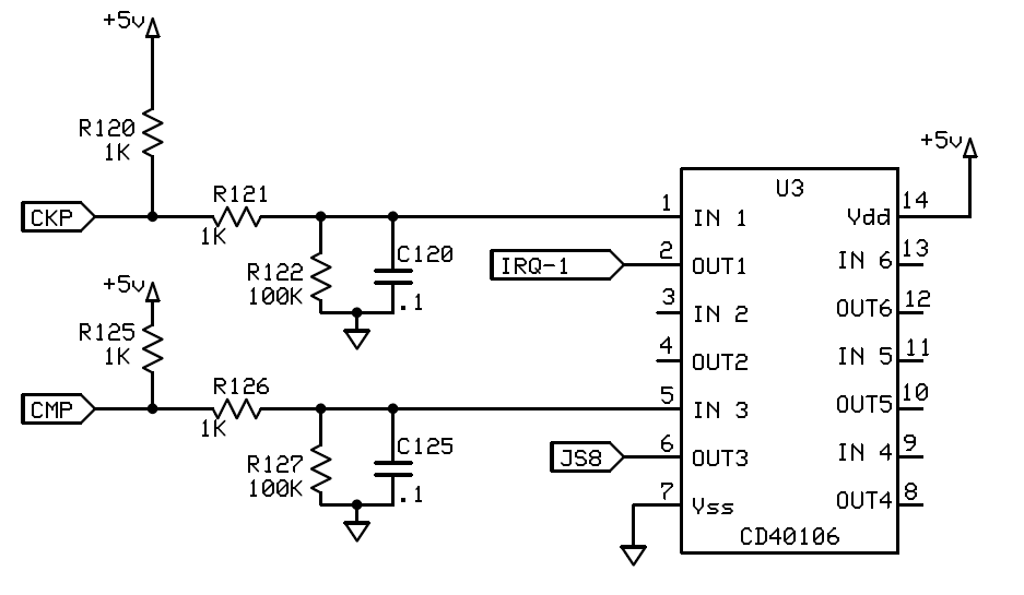
If you want a proven reliable input circuit, build this:

Originally Posted by Joe Perez
The value and stability of C120 and C125 are highly critical. Use low-tolerance parts here (eg: 5%, C0G).
I would shrink them to 10 nF each, and 10% X7R type would be fine. In this thread
https://www.miataturbo.net/ecus-tuni...-sensor-71726/
10 nF worked well.

0.1 uF would produce a delay of around 100 us, (4° at 7000 RPM) which would vary if the input trigger thresholds of the CDxxxx IC varied, like due to temperature.

BTW one thing the opto-isolator circuit does, is be slow and not respond to very thin spikes of noise.
JasonC SBB is offline  
Old 04-05-2013, 01:40 PM
  #56  
Bannisheded
iTrader: (1)
 
GAMO's Avatar
 
Join Date: Jan 2008
Posts: 203
Total Cats: 9
Default

With a .1uF cap, the ECU wouldn't even sync since the RC constant was so high.

As for the 40106 discussion, it's an excellent trigger due to it's delay (lack thereof) and hysteresis. I think for 10V, it has about 3.5V of Hysteresis, and the response time is sub-100ns.

Glad the optoisolator worked.
GAMO is offline  
Old 04-05-2013, 02:03 PM
  #57  
Boost Pope
iTrader: (8)
 
Joe Perez's Avatar
 
Join Date: Sep 2005
Location: Chicago. (The less-murder part.)
Posts: 33,050
Total Cats: 6,608
Default

Originally Posted by GAMO
With a .1uF cap, the ECU wouldn't even sync since the RC constant was so high.
I have built that exact circuit a number of times, and it syncs just fine. Probably wouldn't be a good thing to use with high-toothcount wheels or wheels with very small teeth (NBs), but on NAs it's the best thing since sliced bread.

Although it's nice to be able to converse with people who actually understand the concept of an RC filter and how it applies to the real world.
Joe Perez is offline  
Old 04-05-2013, 02:18 PM
  #58  
Junior Member
Thread Starter
iTrader: (1)
 
duffbuster243's Avatar
 
Join Date: Sep 2010
Location: Scranton PA
Posts: 264
Total Cats: 4
Default

Originally Posted by Reverant
You need to set it to falling edge, going high.
Right now its at rising edge going high, I set it to Falling edge going high last night and it died and would not start back up until I changed back to rising edge.
duffbuster243 is offline  
Old 04-05-2013, 02:30 PM
  #59  
Boost Czar
iTrader: (62)
 
Braineack's Avatar
 
Join Date: May 2005
Location: Chantilly, VA
Posts: 79,501
Total Cats: 4,080
Default

what does the composite look like?
Braineack is offline  
Old 04-05-2013, 02:35 PM
  #60  
Junior Member
Thread Starter
iTrader: (1)
 
duffbuster243's Avatar
 
Join Date: Sep 2010
Location: Scranton PA
Posts: 264
Total Cats: 4
Default

Originally Posted by Braineack
what does the composite look like?
I didn't have time last night to take a composite log or any log for that matter, I probably won't be able to get a log until sunday evening. My weekend is booked up with a bunch of things, none of which I want to do. It sucks.
duffbuster243 is offline  


Quick Reply: Second optoisolator on MS2


All times are GMT -4. The time now is 04:59 AM.