
Second optoisolator on MS2


email DIYAUTOTUNE.
I've never heard of a DIYPNP losing sync like that.
the crank signal goes in on the opto circuit and cam VR.
it appears your cam signal is getting out of whack every now and again--it's still reading it, but the pattern gets off. I'd almost want to look into the CAS.
I've never heard of a DIYPNP losing sync like that.
the crank signal goes in on the opto circuit and cam VR.
it appears your cam signal is getting out of whack every now and again--it's still reading it, but the pattern gets off. I'd almost want to look into the CAS.
Reply
 0
0

0

Newb
Joined: Jun 2014
Posts: 18
Total Cats: 0
It's been a couple month, I have done a lot to try to figure out what is going on here with my MSII DIYPNP.
I swapped the CAS, resoldered VR2+ related connections on the unit, checked and cleaned ECU grounds, checked wiring and plug connection related to CAS. The problem still persist. Note, I am only getting drop in cam signal VR2+ and never crank from every composite log I have recorded. This seems to happen more consistently when some sensor is open circuited and then reconnected; Example my wideband 12V connector was loose and I got crazy amount of sync loss.
Finally, I bit the bullet and purchased a MS2PNP. No sync loss so far in conditions where I would definitely had before.
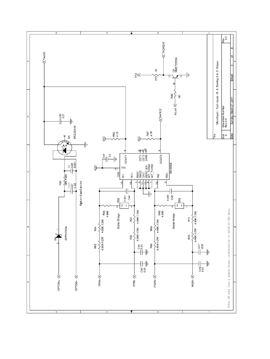
I took a look at the microsquirt schematic and it looks like the cam signal doesnt have any conditioner but the crank does have an optoisolator. Not sure if MS2PNP have any conditioner for cam signal, I would assume so.
94-95 miata doesnt seem like it has separate sensor ground (looking at the electrical schematics) unlike 90-93, I could be wrong. I am guessing maybe DIYPNP MSII suffers the same problem here. Just want to share what I went through so far and look for some opinions since I am pretty new so this megasquirt stuff.
I swapped the CAS, resoldered VR2+ related connections on the unit, checked and cleaned ECU grounds, checked wiring and plug connection related to CAS. The problem still persist. Note, I am only getting drop in cam signal VR2+ and never crank from every composite log I have recorded. This seems to happen more consistently when some sensor is open circuited and then reconnected; Example my wideband 12V connector was loose and I got crazy amount of sync loss.
Finally, I bit the bullet and purchased a MS2PNP. No sync loss so far in conditions where I would definitely had before.
I took a look at the microsquirt schematic and it looks like the cam signal doesnt have any conditioner but the crank does have an optoisolator. Not sure if MS2PNP have any conditioner for cam signal, I would assume so.
94-95 miata doesnt seem like it has separate sensor ground (looking at the electrical schematics) unlike 90-93, I could be wrong. I am guessing maybe DIYPNP MSII suffers the same problem here. Just want to share what I went through so far and look for some opinions since I am pretty new so this megasquirt stuff.
Reply
0
0
When you say DIYPNP MSII you just mean DIYPNP.
you dont mean the MSPNP2, correct?
if so, please just use DIYPNP, otherwise it's confusing. MSII is implied.
the cam signal on the DIYPNP goes through a MAX9926.
I've built literally hundreds of DIYPNPs and never heard of one once losing the cam signal. Not saying it can't happen, but it's unusal to me.
Last edited by Braineack; Jul 30, 2015 at 11:28 AM.
Reply
0
0
Newb
Joined: Jun 2014
Posts: 18
Total Cats: 0
Reply
0
0
Newb
Joined: Jun 2014
Posts: 18
Total Cats: 0
Is this on the microsquirt unit or the 1.5x diypnp board?
Edit: I am guessing it's on microsquirt because I been told that the 1.5x diypnp board has only a simple pullup circuit and then it feeds into VR2IN+ of the microsquirt, looking at the schematic of microsquirt, cam signal only goes through an opamp U10B and transistor Q7 then straight into the microcontroller.
Edit: I am guessing it's on microsquirt because I been told that the 1.5x diypnp board has only a simple pullup circuit and then it feeds into VR2IN+ of the microsquirt, looking at the schematic of microsquirt, cam signal only goes through an opamp U10B and transistor Q7 then straight into the microcontroller.
Last edited by Zhimin90; Jul 30, 2015 at 11:11 AM.
Reply
0
0
the microsquirt unit. U10 is a MAX9926.
yeah the DIYPNP connector board itself only provides the pullup for the signal, but the microsquirt itself has a vr conditioner.
it's supossed to be a pretty damn good conditioner too.
yeah the DIYPNP connector board itself only provides the pullup for the signal, but the microsquirt itself has a vr conditioner.
it's supossed to be a pretty damn good conditioner too.
Last edited by Braineack; Jul 30, 2015 at 11:39 AM.
Reply
0
0
Newb
Joined: Jun 2014
Posts: 18
Total Cats: 0
Reply
0
0
oh interesting, i havent kept up with that. I didnt start building DIYPNPs until late 2009, i believe that was after that latest microquirt module version was already released.
now that I think about it, IIRC, the older version still went through a conditioner, but it was similar to like what the MS3 Expander board or v3.0/3.57 mainboard uses.
now that I think about it, IIRC, the older version still went through a conditioner, but it was similar to like what the MS3 Expander board or v3.0/3.57 mainboard uses.
Last edited by Braineack; Jul 30, 2015 at 11:56 AM.
Reply
0
0
Newb
Joined: Jun 2014
Posts: 18
Total Cats: 0
Reply
0
0
so youre right. i just looked for the first 16-pin IC I saw. :P
here: http://www.msextra.com/doc/general/p...squirt_2_0.pdf
it's still going through the MC34072.
so the similar circuit we use on v3.0 and v3.57 mainboards.
that's what I thought it was using, but that docs screwed me up showing the MAX9926--i guess that's in the works?
here: http://www.msextra.com/doc/general/p...squirt_2_0.pdf
it's still going through the MC34072.
so the similar circuit we use on v3.0 and v3.57 mainboards.
that's what I thought it was using, but that docs screwed me up showing the MAX9926--i guess that's in the works?
Last edited by Braineack; Jul 30, 2015 at 12:35 PM.
Reply
0
0
Newb
Joined: Jun 2014
Posts: 18
Total Cats: 0
In V3.0 microsquirt, they revised this circuit. That leads me to believe they probably had some issues with applications with more noisy in the cam or crank signals. My DIYPNP works and gets the cam signal but just not all the time. The cam signal just seems fragile to other sensors.
Reply
0
0
Reply
0
0

Thread
Thread Starter
Forum
Replies
Last Post
StratoBlue1109
Miata parts for sale/trade
21
Sep 30, 2018 01:09 PM
stubbs
MEGAsquirt
14
Feb 13, 2009 11:32 AM


