
Sequential cop driver


Thread Starter
Junior Member
Joined: Jul 2007
Posts: 57
Total Cats: 0
I've built 4 identical circuits to run sequential COPS. I'm using toyota cops.
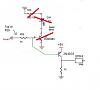
Here is a pic of the circuits I've built and I'm wondering if these make sense to run the toyota cops which I believe are active high devices.
I've set spark out to not inverted and I'm using 4/1 cas. The car wouldn't start and just spits, it's all out of sync. Before attempting further starting, I am wondering if the circuits I've build make sense.
Thanks for your help
Reply
 0
0

0


Thread Starter
Junior Member
Joined: Jul 2007
Posts: 57
Total Cats: 0
the idea is to have it normally grounded and around 5 (4.3 should be enough) to trigger the COP internal igniters. I'm guessing the COP igniters are active high devices so whenever I give it 5 volts, it should fire. Am I wrong? Is it ground switching instead? What do you think would be a better circuit?
Reply
0
0
Joined: Sep 2005
Posts: 34,428
Total Cats: 7,548
From: Chicago. (The less-murder part.)
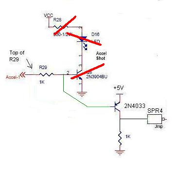
No, you've got it correct- +5 to turn on the primary, GND to turn it off. I'm just not sure why you'd deliberately voltage-limit the trigger.
Here's the traditional output circuit that most of us use:

As you can see, a full +5v is available to drive the coil trigger. The circuit has the disadvantage of being inverting (so the coil trigger floats to +5 when the CPU is off) so I did a revised version that de-inverts it:

In both of the above designs, you have no voltage division, and just a bit of current limiting through the pullup.
Here's the traditional output circuit that most of us use:
As you can see, a full +5v is available to drive the coil trigger. The circuit has the disadvantage of being inverting (so the coil trigger floats to +5 when the CPU is off) so I did a revised version that de-inverts it:
In both of the above designs, you have no voltage division, and just a bit of current limiting through the pullup.
Reply
0
0
Thread Starter
Junior Member
Joined: Jul 2007
Posts: 57
Total Cats: 0
I've seen your work (good stuff btw), I totally understand what you did and what is the point. I just thought the circuit i've built is simpler but it's true that the trigger doesn't get a full 5V and a 4.3 instead so I'll have to revise it to something similar to yours.
The only thing I don't like about the above circuit is that the 2nd transistor conducts all the time but I think it's the only way to get a full 5 volts at the output.
I will try taking out the spark plugs with the COPS and while cranking see, if I'm getting any spark that way. My guess is that they fire but at the wrong moment, hence I get kickbacks and backfires. Hell, I might just connect the processor through resistors to the COPs just to see if they work.
Reply
0
0

Thread
Thread Starter
Forum
Replies
Last Post
bigmackloud
Miata parts for sale/trade
19
Jan 8, 2021 11:24 AM


