Notices
MEGAsquirt A place to collectively sort out this megasquirt gizmo

Standalone 1.6 Wiring Diagram / Schematic

Old Jan 6, 2009 | 09:26 AM
  #21  
Braineack's Avatar
Boost Czar
iTrader: (62)
 
Joined: May 2005
Posts: 80,552
Total Cats: 4,368
From: Chantilly, VA
Default

Originally Posted by 92Miata
Thanks alot for that diagram though helped alot in wiring my car.

you should be thanking me....all he did was take my two diagrams and connect the lines.


follow the DIY MS link....
Old Jan 6, 2009 | 01:34 PM
  #22  
miatamoxie's Avatar
Junior Member
iTrader: (1)
 
Joined: Apr 2008
Posts: 174
Total Cats: 0
From: Springfield Oregon
Default

'tis true....it is just an easier to read version of Braineack's diagrams....so thanks Brain!
Old Jan 6, 2009 | 02:25 PM
  #23  
92Miata's Avatar
Junior Member
iTrader: (3)
 
Joined: Jul 2008
Posts: 308
Total Cats: 1
From: Pinellas park Fl
Default

Originally Posted by Braineack
you should be thanking me....all he did was take my two diagrams and connect the lines.


follow the DIY MS link....

Well i will thank you for the DIY thread because i followed that for the fan and spark mods. Thanks alot for that!
Old Jan 19, 2009 | 04:47 AM
  #24  
ogwazza's Avatar
Thread Starter
Junior Member
iTrader: (6)
 
Joined: Aug 2008
Posts: 248
Total Cats: 3
From: New Zealand
Default

Alright, Just adding this extra diagram, even tho the threads been Jackd- Dam newbs!

I did this so I knew relative wiring lengths

[IMG][/IMG]
Old Mar 19, 2009 | 12:05 AM
  #25  
557795's Avatar
Newb
 
Joined: May 2008
Posts: 19
Total Cats: 0
From: New Zealand
Default

will this diagram work with ms2?

cheers
557795
Old Mar 19, 2009 | 05:27 PM
  #26  
ogwazza's Avatar
Thread Starter
Junior Member
iTrader: (6)
 
Joined: Aug 2008
Posts: 248
Total Cats: 3
From: New Zealand
Default

Im going to assume it would be pretty close. Although if you just use universal relays, it is much cleaner and easier (which is what I ended up doing)
Old Mar 29, 2009 | 04:43 AM
  #27  
ogwazza's Avatar
Thread Starter
Junior Member
iTrader: (6)
 
Joined: Aug 2008
Posts: 248
Total Cats: 3
From: New Zealand
Default

(Slight Update)
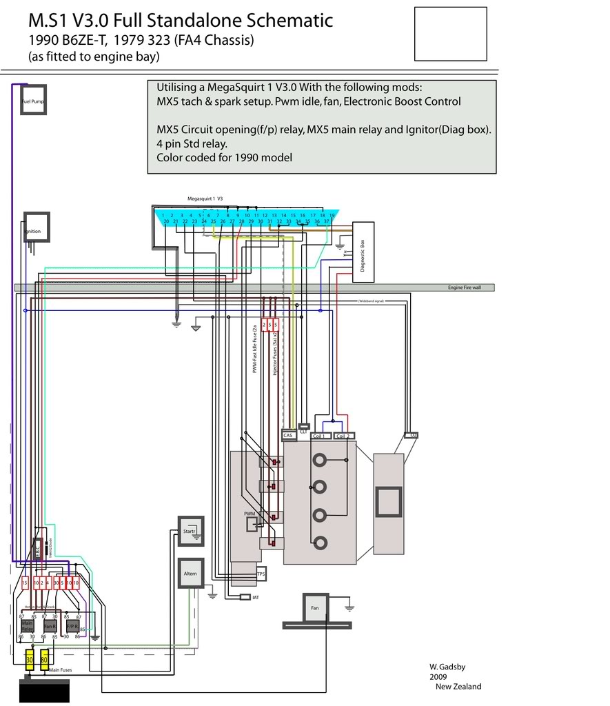
My diagram is still a bit of a work in progress. What I didn't put into the diagram and according to Joe Perez (people who know a S#!T load more than me -see the link below), is that if you are using a 90-93 TPS you dont connect pin 22 and pin 26. I didn't know this at the time, but have left the wires in anyways, for later, if I end up wanting to update my TPS to a proper position sensor rather than the on/off switch the 90-93's come out with.


90-93 db37 Standalone pinout
Old Dec 29, 2009 | 04:31 AM
  #28  
ogwazza's Avatar
Thread Starter
Junior Member
iTrader: (6)
 
Joined: Aug 2008
Posts: 248
Total Cats: 3
From: New Zealand
Default

Name:  B6ZET323WiringSchematic.jpg
Views: 3617
Size:  113.7 KB

update for the above pic
Related Topics
Thread
Thread Starter
Forum
Replies
Last Post
Zaphod
MEGAsquirt
47
Oct 26, 2018 11:00 PM
slomiata
MEGAsquirt
5
Oct 7, 2015 01:11 PM
Trent
WTB
2
Oct 1, 2015 12:15 PM
btabor
ECUs and Tuning
10
Sep 28, 2015 05:33 PM


Thread Tools
Search this Thread

All times are GMT -4. The time now is 10:39 AM.