Sync issues with Secondhand MS2E
#1
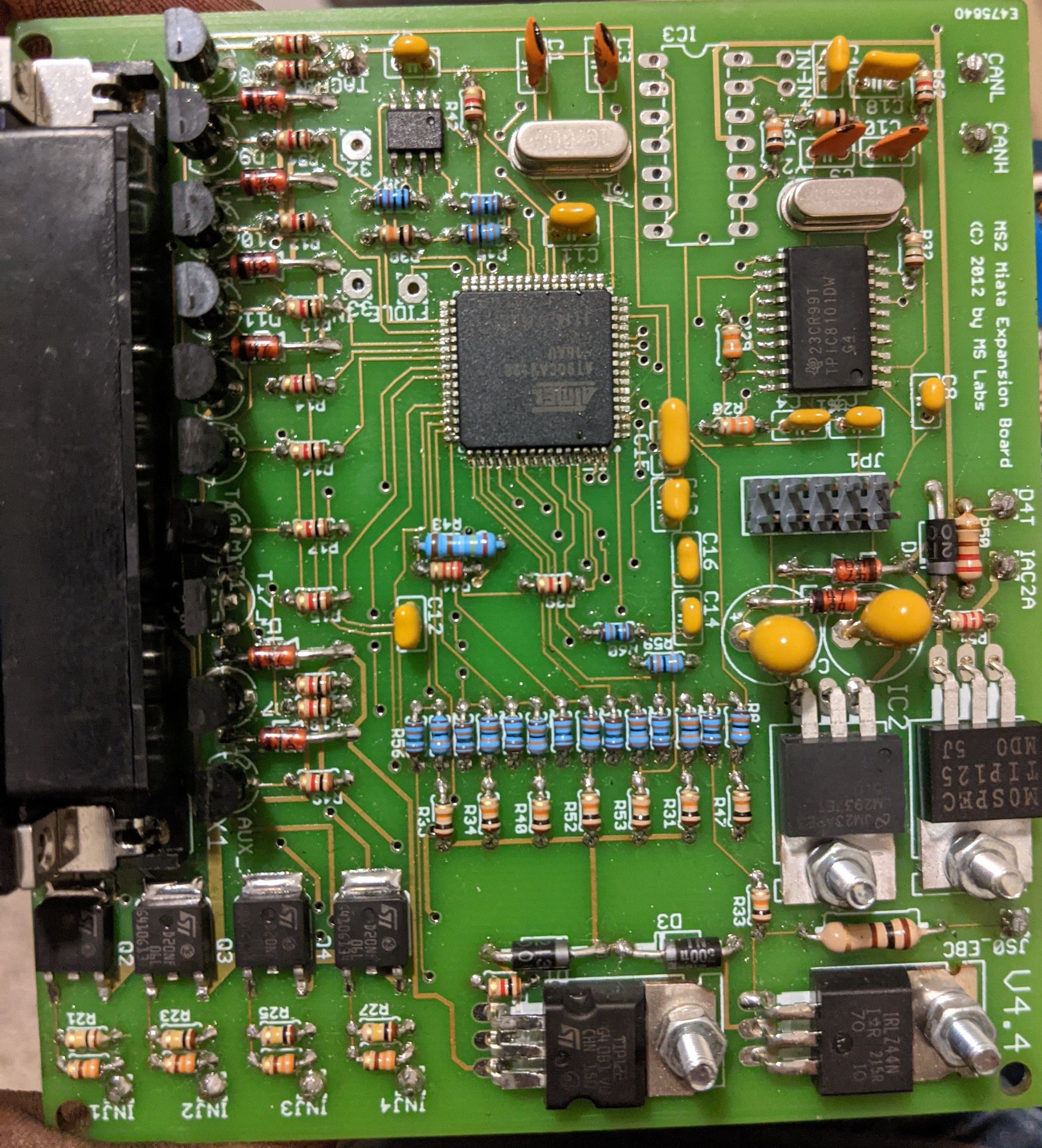
Hey Everyone, as you may have read in a previous thread, i have recently acquired a MSlabs MS2 Enhanced. it was built for a 90-97 miata, according to the case.
my issue is that i have no sync at all. it appears like i have no cam signal input to it. i do see crank input though. Falling/rising edge made no difference.
I have it set up as 4g63 and believe i have everything setup correctly. but nothing shows up..
i can hook up my speeduino and have sync from it, and i even borrowed a good friends mspnppro and i have sync with it without any loss over multiple hundreds of miles from each ecu
so im guessing i have a hardware problem with the ms2Enhanced.
i am attaching my cranking logs, tune files, and .inis from both the ms2e and my speeduino, just to show the difference.
Kinda getting the feeling that i have a fancy paperweight here.
Last edited by Stormfinder; 12-06-2020 at 03:54 PM.
#2
Ok so trying to check the wiring for the cam signal and I am more confused then ever.
The crank signal is coming in on db37 pin 24, goes to tachselect, then to xg1, where I lose it after there. But it works as far as I can tell, from the datalog above.
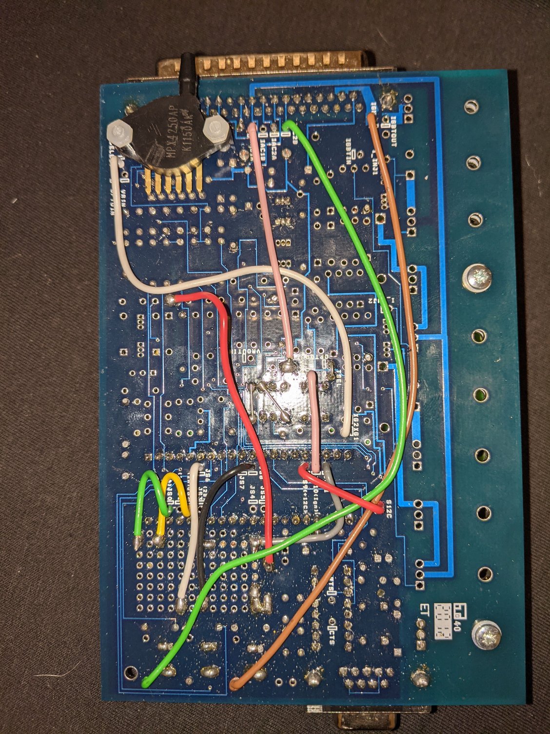
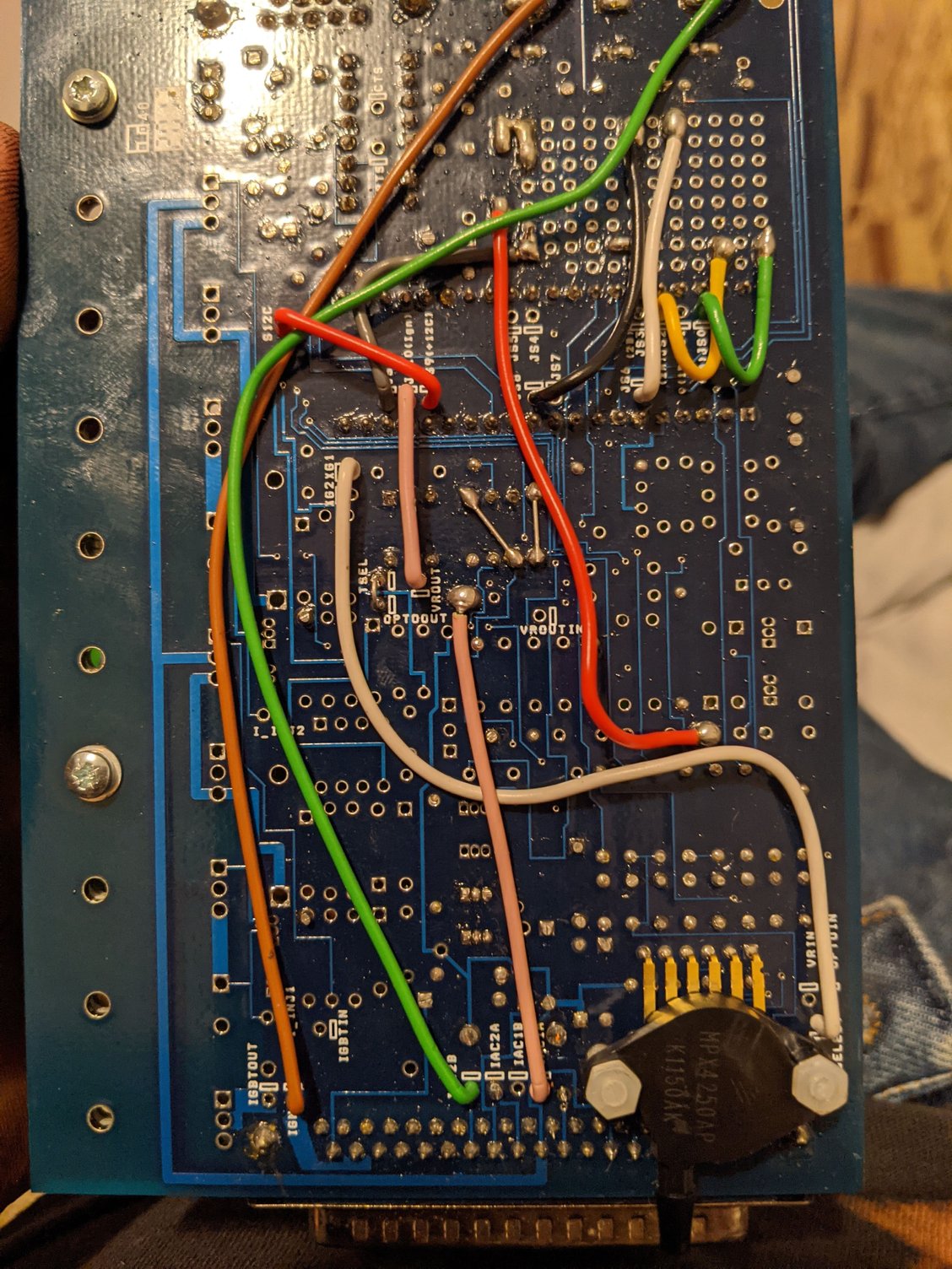
The cam signal comes in on db37 pin 25, goes to IAC1A, then to r52 both top and middle holes, then to the middle pin of u7 on the side closest to the cpu. I lose it after there.
#4
Elite Member

iTrader: (10)
Join Date: Jun 2006
Location: Athens, Greece
Posts: 5,979
Total Cats: 356
Start by making sure no one has flashed a Microsquirt/Microsquirt Module firmware on it, as this will happen if you flash the wrong firmware type. It needs to have the correct firmware type on it.
#7
Elite Member

iTrader: (10)
Join Date: Jun 2006
Location: Athens, Greece
Posts: 5,979
Total Cats: 356
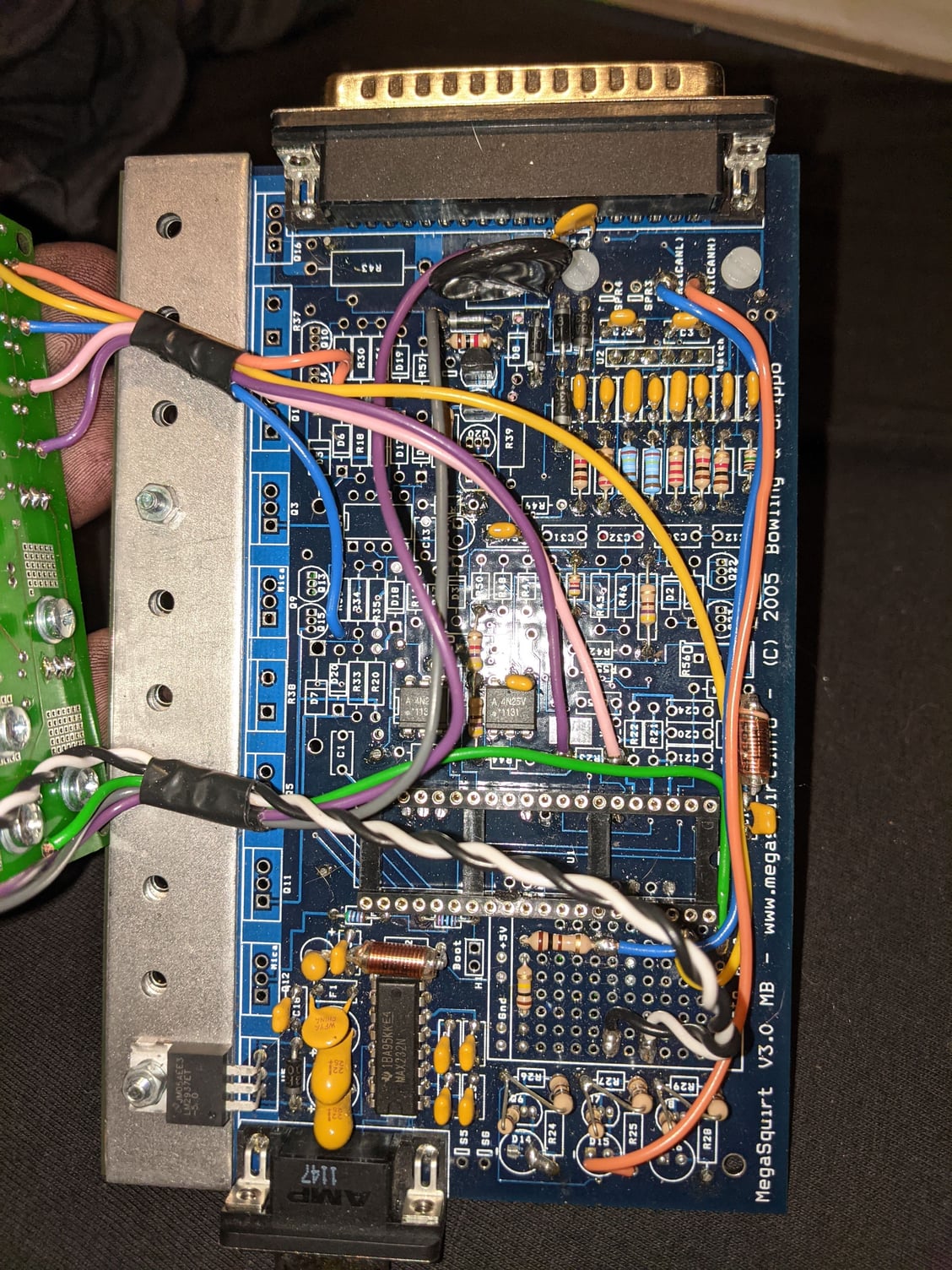
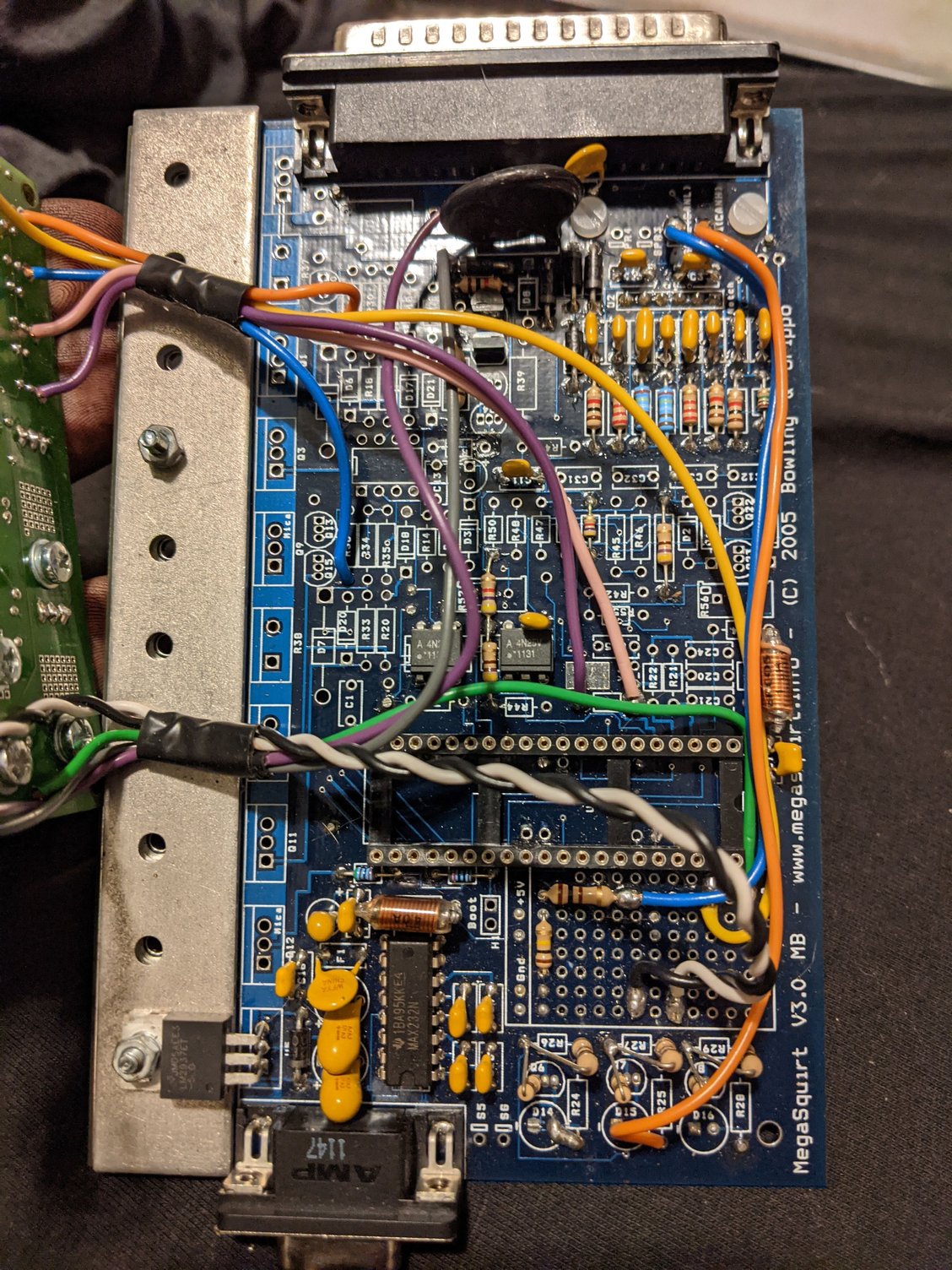
It's a V3 mainboard so you can get the schematics for it and trace the cam routing. It's been 8 years since we've stopped building these so I can't really help. The signal goes to one of the two white optoisolators on the board, and from there to the CPU.
#12
Elite Member

iTrader: (10)
Join Date: Jun 2006
Location: Athens, Greece
Posts: 5,979
Total Cats: 356
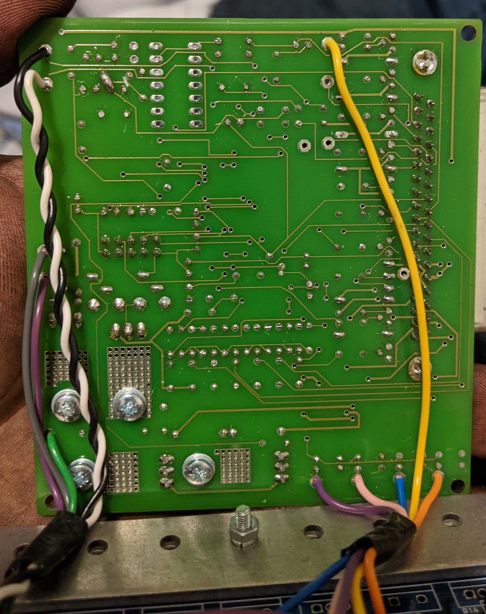
The two pink wires on the bottom are the cam signal (in from the sensor, VRout from the 4n25 optoisolator to the CPU). The 4N25 on the top that has the capacitor soldered directly on it is for the cam circuit, which consists of this 4N25, the cap on it and the two resistors directly above it (one 470R which acts as a 5V feed and current limiting for the light emitter in the 4N25 and one 4.7K which acts as a pullup for the open collector output of the 4N25). Both resistors are connected together on one end, this is the 5V for them, so the other end of each resistor is the sensor (470) and the CPU output (4.7K).
#14
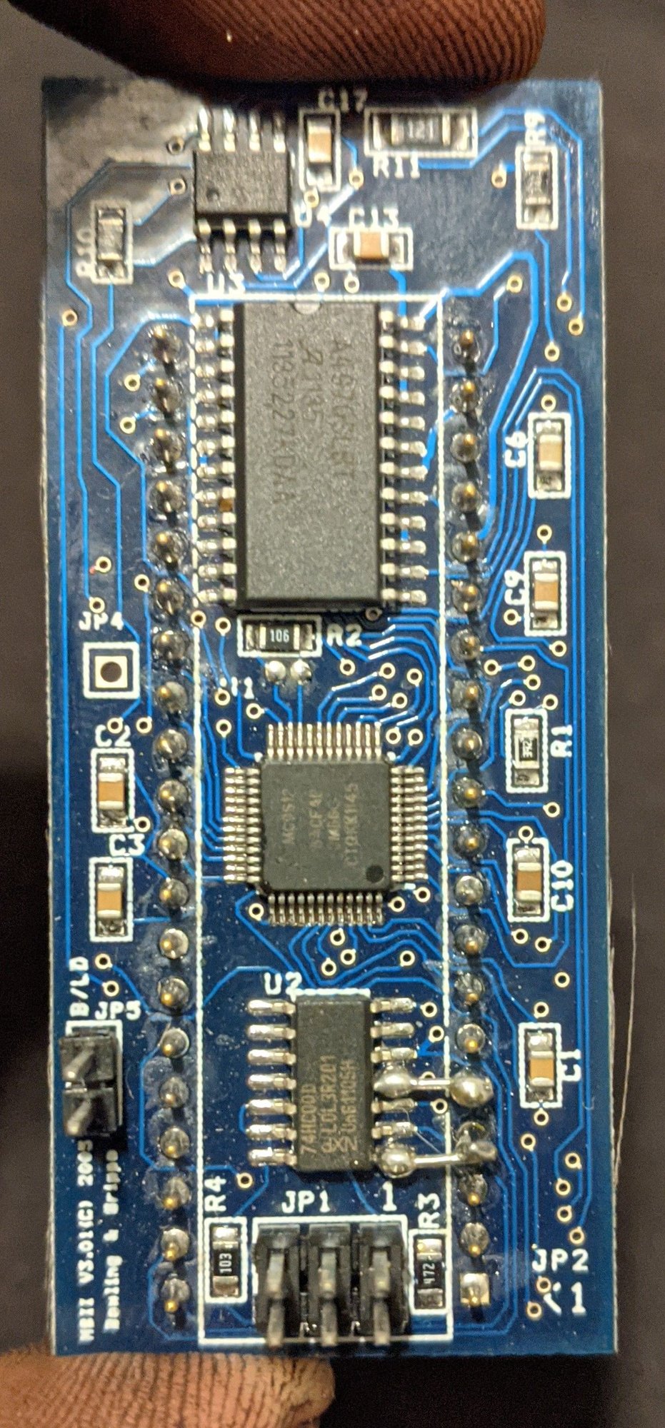
UPDATE!! Thanks to Servaas, i was able to find that it was the daughterboard that was dead on my hardware, js10 was stuck high at all times, even on different hardware, . with a test ms2 daughterboard it worked great, so i have ordered a new one from diy.
Wanted to post the update and put an end to the story if anyone wondered.
Wanted to post the update and put an end to the story if anyone wondered.
Thread
Thread Starter
Forum
Replies
Last Post


