MS2 v3 No RPMs with JimStim. Pictures and Composite File Attached
 01-03-2015, 02:31 PM
#1
Junior Member
Thread Starter
iTrader: (1)

Join Date: Aug 2014
Location: Wisconsin
Posts: 78
Total Cats: 12
Hello All,
I have built my MS2. Some things are working and some things are not.
Most importantly, I cannot see any RPMs when using my JimStim. Please let me know if any further information would be helpful to help me.
'94 mx-5
MegaSquirt 2 v 3.0
JimStim v 1.5
TunerStudio MS Lite v2.6.04
MS2/Extra release 3.3.3 20141112
Spark Mode: 4G63
Dials that work
� TPS
� CLT
� EGO (Narrow)
� MAT
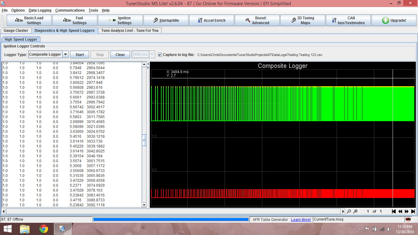
Signals show with Composite logger when RPM C is turned. Attached.
I don�t know how to view composite logger files (CSV�s)
I followed MSExtra for secondary tach input w/ change suggested by Braineack
https://www.miataturbo.net/megasquir...jimstim-81956/
5.2.3
a) Solder a link between VRIN and TACHSELECT
b) Solder a wire between VrOUTInv and TSEL
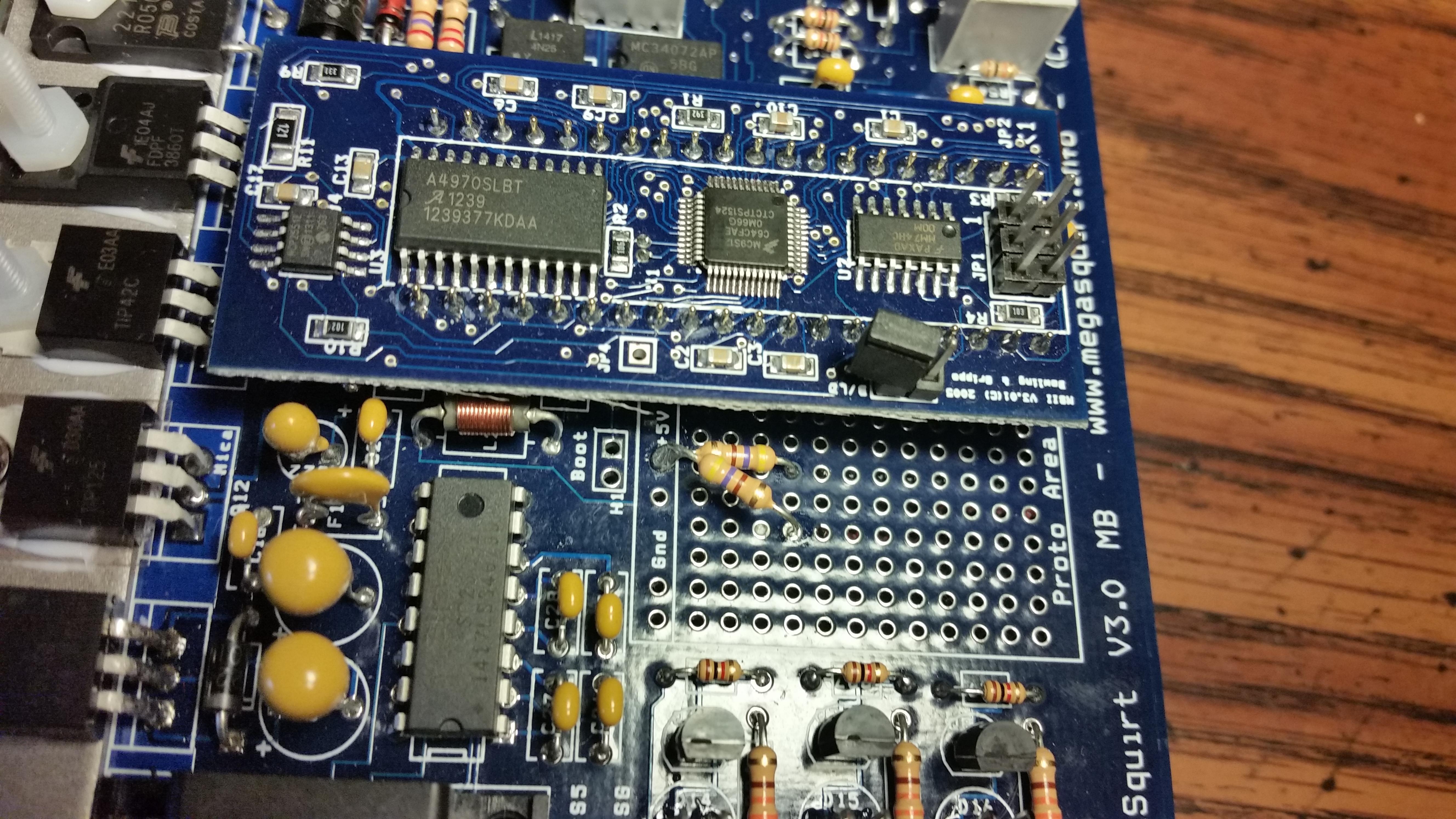
c) Install a 1k resistor (any value 470R - 2k2 is likely OK) in the proto area. Connect one end to the 5V hole and
join the other end to VRIN with a jumper wire.
d) With a small screwdriver, turn the pots, R52 and R56, about 12 turns anticlockwise (sometimes you may feel
a "click" when the end position is reached, they can't be damaged by turning too far.) and then turn R56 back
about 6 turns clockwise.
5.2.14.2 Adding a cam sensor input - hall sensor / optical sensor
This option uses the spare opto-isolator on the mainboard for the cam input and matches the polarity inversion
of the VR/universal tach input.
This section is for open-collector sensors as covered in 5.2.3 that ground switch only.
a) The OptoIn pad should be connected to a spare pin on the main DB37 connector (e.g. SPR3)
b) Connect OptoOut to JS10 (ensuring that nothing else is connected.)
c) Jumper XG1 - XG2
d) Check that R12 is a 390R to 470R resistor, replace if not.
e) Install a 470R 1/4W resistor on the proto area to +5V.
f) Jumper the other end of the 470R resistor to OptoIn (joining the jumper wire there.)
g) Ensure that C30 is not fitted.
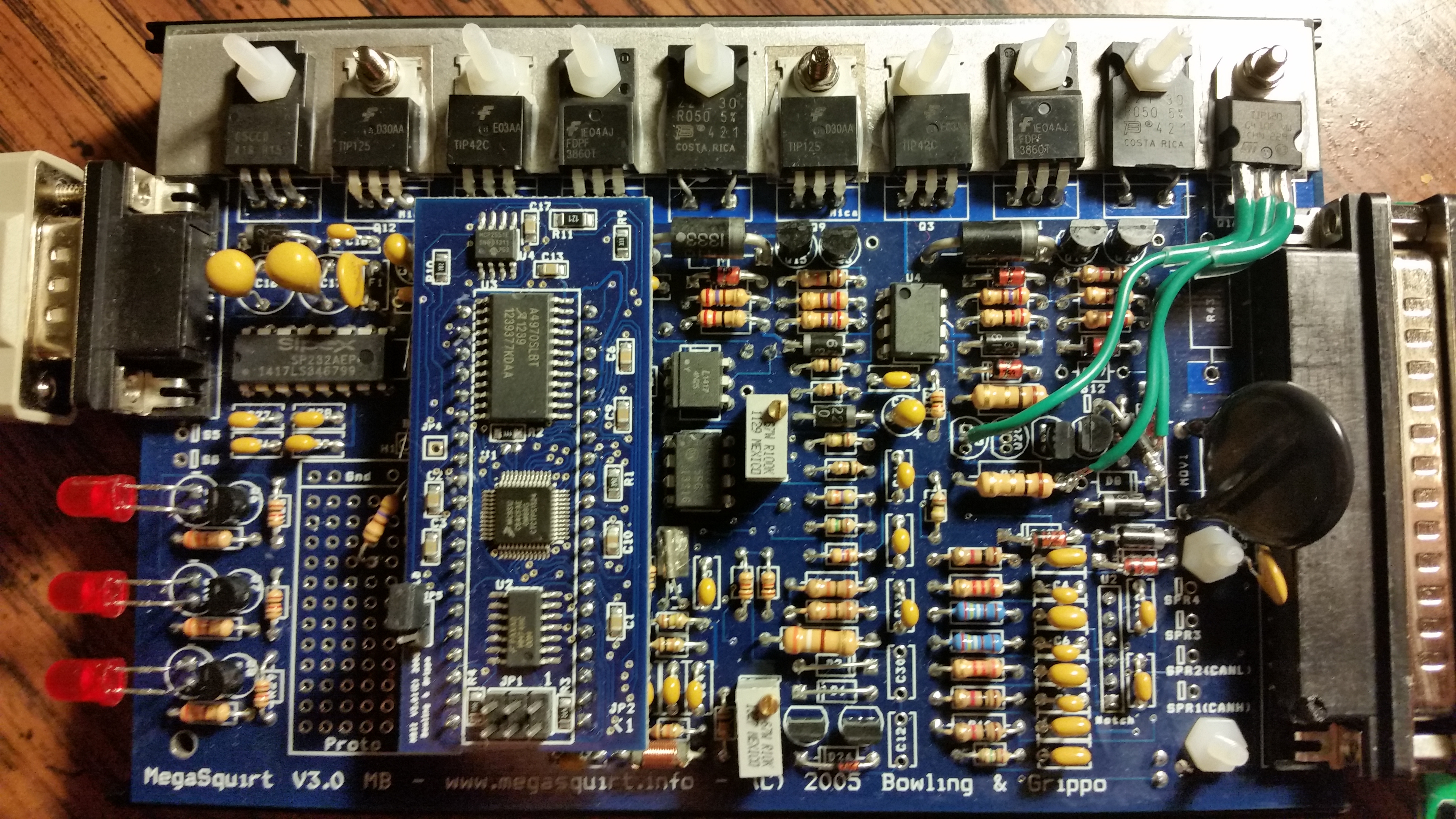
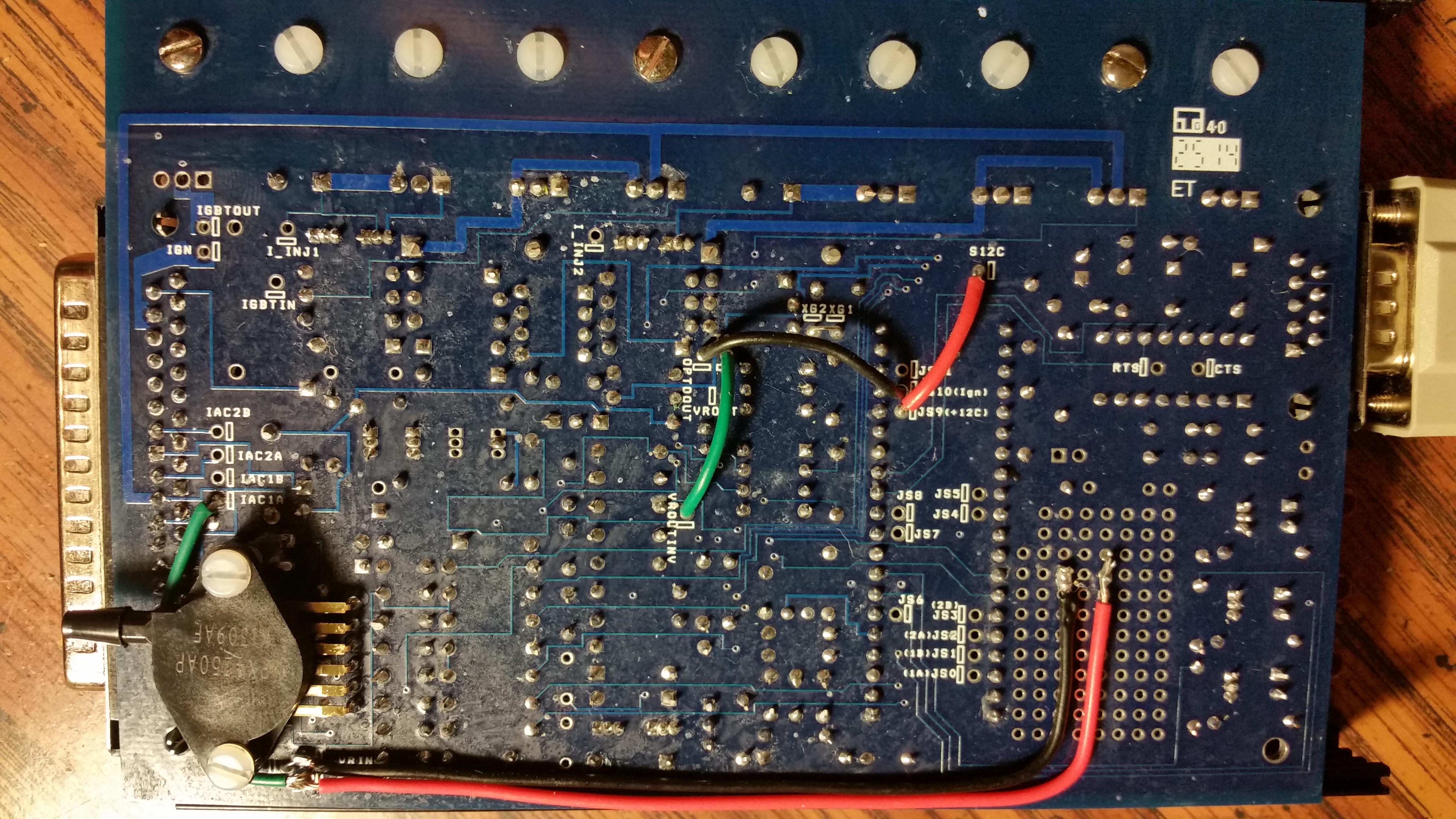
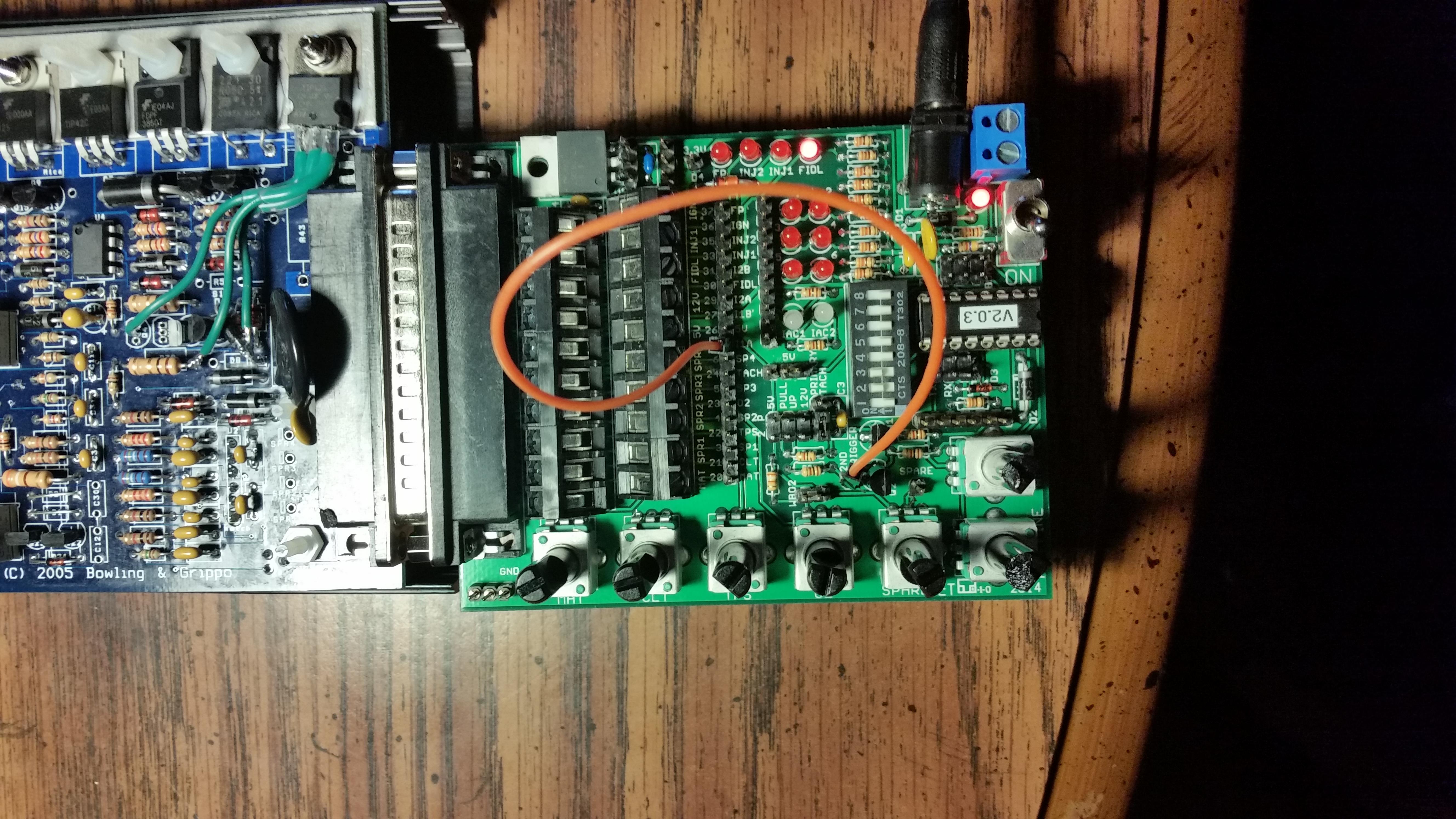
Mods done
Red Jump S12C -> JS9(+12c) JS0-JS4 In/outs
Green Jump TSel -> VROutInv Tach
Black Jump 470oProto-> OptoIn 2nd tach in
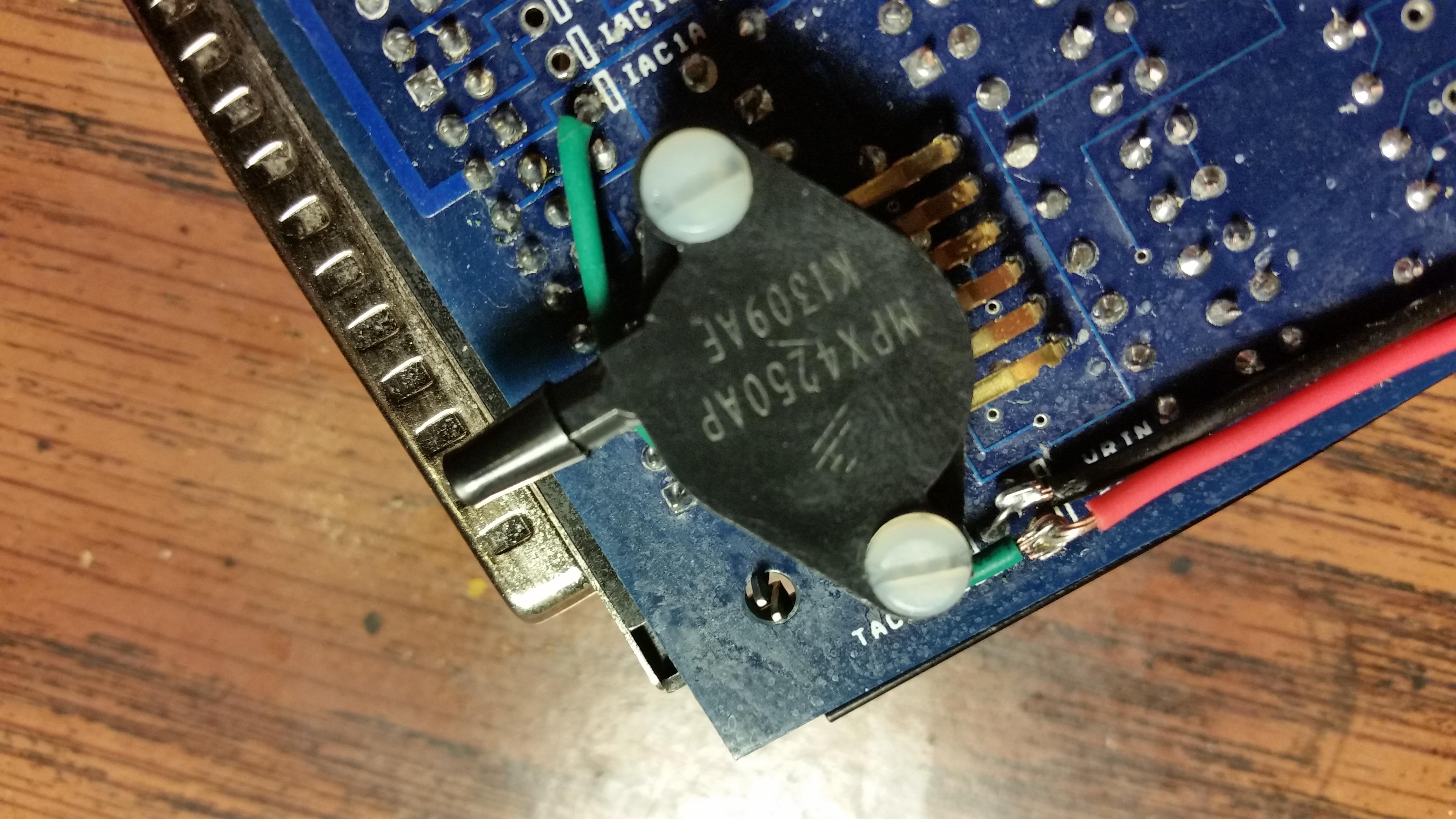
Green Jump IAC1A -> OptoIn 2nd tach in
Lead Jump XG1 -> XG2 2nd tach in
Black Jump JS10 -> OptoOut 2nd tach in
Lead Jump VRIN -> TachSelect
Red Jump OptoIN -> Proto
I believe I still need to modify the board for another ignition out signal for the second ignition coil but I�ll work on that after this is resolved.
I have the JimStim supplying a signal with the Miata (4g63) dip switch setup and the secondary tach signal jumpered to Pin 25 (IAC1A). The RPM jumper is setup for square wave.
Can someone help me so I can get �Not RPM Synced� fixed and start seeing RPMs in TunerStudio? I searched and searched but not many people opt for this secondary tach in setup.
Thanks,
Chris
I have built my MS2. Some things are working and some things are not.
Most importantly, I cannot see any RPMs when using my JimStim. Please let me know if any further information would be helpful to help me.
'94 mx-5
MegaSquirt 2 v 3.0
JimStim v 1.5
TunerStudio MS Lite v2.6.04
MS2/Extra release 3.3.3 20141112
Spark Mode: 4G63
Dials that work
� TPS
� CLT
� EGO (Narrow)
� MAT
Signals show with Composite logger when RPM C is turned. Attached.
I don�t know how to view composite logger files (CSV�s)
I followed MSExtra for secondary tach input w/ change suggested by Braineack
https://www.miataturbo.net/megasquir...jimstim-81956/
5.2.3
a) Solder a link between VRIN and TACHSELECT
b) Solder a wire between VrOUTInv and TSEL
c) Install a 1k resistor (any value 470R - 2k2 is likely OK) in the proto area. Connect one end to the 5V hole and
join the other end to VRIN with a jumper wire.
d) With a small screwdriver, turn the pots, R52 and R56, about 12 turns anticlockwise (sometimes you may feel
a "click" when the end position is reached, they can't be damaged by turning too far.) and then turn R56 back
about 6 turns clockwise.
5.2.14.2 Adding a cam sensor input - hall sensor / optical sensor
This option uses the spare opto-isolator on the mainboard for the cam input and matches the polarity inversion
of the VR/universal tach input.
This section is for open-collector sensors as covered in 5.2.3 that ground switch only.
a) The OptoIn pad should be connected to a spare pin on the main DB37 connector (e.g. SPR3)
b) Connect OptoOut to JS10 (ensuring that nothing else is connected.)
c) Jumper XG1 - XG2
d) Check that R12 is a 390R to 470R resistor, replace if not.
e) Install a 470R 1/4W resistor on the proto area to +5V.
f) Jumper the other end of the 470R resistor to OptoIn (joining the jumper wire there.)
g) Ensure that C30 is not fitted.
Mods done
Red Jump S12C -> JS9(+12c) JS0-JS4 In/outs
Green Jump TSel -> VROutInv Tach
Black Jump 470oProto-> OptoIn 2nd tach in
Green Jump IAC1A -> OptoIn 2nd tach in
Lead Jump XG1 -> XG2 2nd tach in
Black Jump JS10 -> OptoOut 2nd tach in
Lead Jump VRIN -> TachSelect
Red Jump OptoIN -> Proto
I believe I still need to modify the board for another ignition out signal for the second ignition coil but I�ll work on that after this is resolved.
I have the JimStim supplying a signal with the Miata (4g63) dip switch setup and the secondary tach signal jumpered to Pin 25 (IAC1A). The RPM jumper is setup for square wave.
Can someone help me so I can get �Not RPM Synced� fixed and start seeing RPMs in TunerStudio? I searched and searched but not many people opt for this secondary tach in setup.
Thanks,
Chris

Reply
 0
0

0
01-06-2015, 12:13 AM
#2
Junior Member
Thread Starter
iTrader: (1)
Join Date: Aug 2014
Location: Wisconsin
Posts: 78
Total Cats: 12
Hi All,
I found this post from Braineak showing what the composite logger should look like for an MSIII v3.57 and a different year motor. I assume it should look the same on mine.
Thread: https://www.miataturbo.net/megasquir...cas-cam-60824/
Picture of healthy CMP and CMK i think:
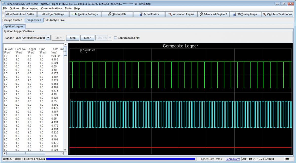
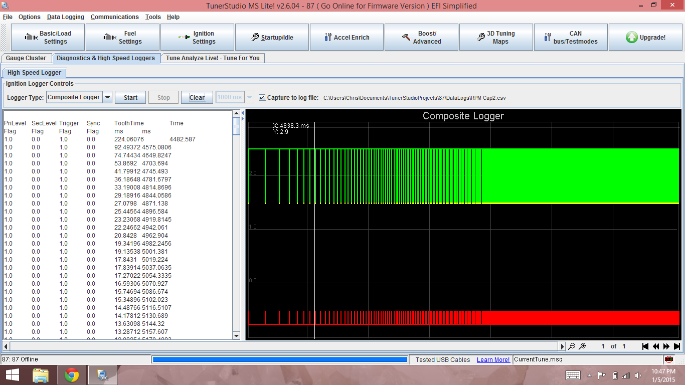
To match I needed to change the Ignition Settings to falling edge also as Braineak suggests to that user. Now, I see a signal that matches the top one but not the bottom signal.
In that same thread they fiddled with the variable resistors (potentiometers) on their MS3X and found their missing signal. They had to measure voltage between the sensor and a U7 to achieve about half of their 5v signal from the sensor. I'm not sure whether that might be an issue on my board, but I don't know where I would measure voltage between. Anybody have any ideas for me?
~ Chris
I found this post from Braineak showing what the composite logger should look like for an MSIII v3.57 and a different year motor. I assume it should look the same on mine.
Thread: https://www.miataturbo.net/megasquir...cas-cam-60824/
Picture of healthy CMP and CMK i think:
To match I needed to change the Ignition Settings to falling edge also as Braineak suggests to that user. Now, I see a signal that matches the top one but not the bottom signal.
In that same thread they fiddled with the variable resistors (potentiometers) on their MS3X and found their missing signal. They had to measure voltage between the sensor and a U7 to achieve about half of their 5v signal from the sensor. I'm not sure whether that might be an issue on my board, but I don't know where I would measure voltage between. Anybody have any ideas for me?
~ Chris
Reply
0
0

Thread
Thread Starter
Forum
Replies
Last Post


