
very low rpm when ac + clutch


Thread Starter
Senior Member
Joined: Nov 2012
Posts: 650
Total Cats: -480
From: Israel
Hey,
I use DIYPNP on my 97 turbo miata.
When I press the clutch paddle with no ac on, the rpm will go down nice and smooth to around 900 and stay there.
When I do the same with the ac on, the rpm will go down very low 500-600 and almost stall - sometimes it does.
The CL is not even on yet (2sec delay on both situations.
Any help ?
Thanks !
Reply
 0
0

0

Is it a MS1? If it is the MS1 doesnt have the idle up feature. I ran into the same issue. You can play with the Closed loop settings and get it to work however you are going to have a very high idle when the ac is off, however when it is on the idle will be normal. I switched mine back to Warm Up only till my MS2 daughter board gets in and then ill use the idle setting. There is a vid on youtube showing how it works. Much better then then relying on MS1.
Reply
0
0

yeah his fw does that, as well as any of the new 3.3 betas will have the same thing. You also need to re-wire a few things on the board to get it to work right...it's all in gslender's documentation for his mods.
Reply
0
0
Supporting Vendor

Joined: Sep 2006
Posts: 2,332
Total Cats: 67
Can you post a data log of the problem and a copy of your MSQ?
Reply
0
0
Thread Starter
Senior Member
Joined: Nov 2012
Posts: 650
Total Cats: -480
From: Israel
I would like to install gslender fw in order to fix the ac drop, I just do not understand what to do with the wires.
Can you give me a hand ?
I need to use 1K ? where do I need to put it ?
Can you give me a hand ?
I need to use 1K ? where do I need to put it ?
Reply
0
0
I just woke up, so maybe sanity check this.....
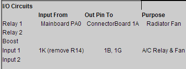
1K (AC switch) should be routed to an input circuit (PE1, PE0, or PA0). I believe I used one of the input circuits for this to protect the ECU.
Signal to enable AC relay (1B, 1G) is routed from an output port (WLED, ALED)
1K (AC switch) should be routed to an input circuit (PE1, PE0, or PA0). I believe I used one of the input circuits for this to protect the ECU.
Signal to enable AC relay (1B, 1G) is routed from an output port (WLED, ALED)
Reply
0
0


That wiring makes no sense. The 1K going directly into the CPU is cause for alarm, it should be going through the input circuit. You have the output traveling through an input circuit, that's silly.
Do:
1K to Input 1 IN (install r14)
Input 1 OUT to PE1
ALED to 1B, 1G
Do:
1K to Input 1 IN (install r14)
Input 1 OUT to PE1
ALED to 1B, 1G
Reply
0
0
Then I'd say your MS is fine. I actually think I wired mine up initially without going thru the input, then re-did it (without ever plugging it back in the car, like you). Never had any sort of issues.
Reply
0
0
Thread Starter
Senior Member
Joined: Nov 2012
Posts: 650
Total Cats: -480
From: Israel
Luckily a fw re-flush helped, I'm back on track again.
I got it updated to 3.3beta13
looks ok, I need to plug it to the car and see.
Thanks !
I did:
1k--->Input2IN
Input2OUT--->PE1
WLED--->1B, 1G
No need to put something on the WLED pull up - right ?
I got it updated to 3.3beta13
looks ok, I need to plug it to the car and see.
Thanks !
I did:
1k--->Input2IN
Input2OUT--->PE1
WLED--->1B, 1G
No need to put something on the WLED pull up - right ?
Last edited by elior77; Jun 11, 2013 at 08:44 AM.
Reply
0
0
Thread Starter
Senior Member
Joined: Nov 2012
Posts: 650
Total Cats: -480
From: Israel
Tuned CL fixed the very low rpm when ac + clutch.
(Use last value or table: use initial value table (CLT) - did the trick, keeps the pwm valve open when rpm drops)
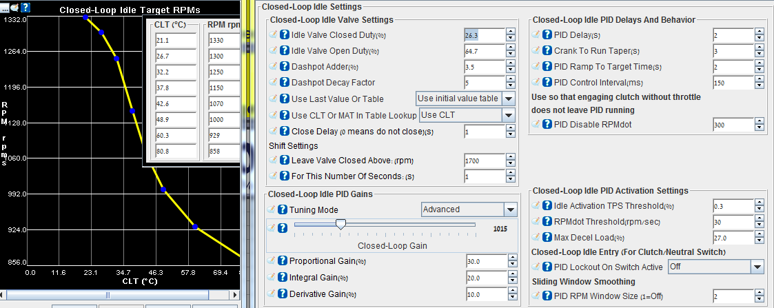
*Just closing up all my threads with the solutions I found.
(Use last value or table: use initial value table (CLT) - did the trick, keeps the pwm valve open when rpm drops)
*Just closing up all my threads with the solutions I found.
Reply
0
0

Thread
Thread Starter
Forum
Replies
Last Post
graexodus
Miata parts for sale/trade
5
Oct 26, 2015 01:48 PM
JesseTheNoob
DIY Turbo Discussion
15
Sep 30, 2015 02:44 PM


