
vvt tuner wiring help!

Thread Starter
Senior Member
iTrader: (1)
Joined: May 2010
Posts: 581
Total Cats: 8
From: Harrisburg, Pa
Ok so I have it wired up right.
I have the crank and cam sensor signals in. OCV in and 12v out, and power and ground.
Now I cant get the car to start. I have it the vvt tuner in NB pass thru trigger out put. My current settings for idle are pwm warmup. I've also tried putting it in closed loop always on with no luck.
Any idea's? Thanks...
Ok here's exactly how I have it wired. Ben said it was ok but I just found a thread where brain walked through it and I might have done it wrong?
I have it as follows.
This is what I'm not sure I did right after reading EO2K's thread
Pins 1, 2, 9, 10. Open because I'm not inputting it to the ecu, nor am I even sure which wires I would need to splice into to do so.
Pin 3 Signal in from camshaft sensor
Pin 4 Signal in from crankshaft sensor
Pins 5, 6, 11, 12, 13. Open because the car is a 2001 so the sensor are already powered and grounded
Pin 7 12V input on durning cranking and when the engine is running. I took this from what used to power the OCV with the stock ecu, via 5amp fuse.
Pin 14 Ground also taken from the crankshaft sensor.
Pins 8, 15. Wired into the OCV.
Last edited by gorillazfan1023; Apr 13, 2013 at 09:44 PM.
Reply
 0
0

0
Thread Starter
Senior Member
iTrader: (1)
Joined: May 2010
Posts: 581
Total Cats: 8
From: Harrisburg, Pa
I'm at my wits end. I wired it as brain and rev suggested in this thread (https://www.miataturbo.net/megasquir...nms-ecu-69111/).
It will not start. I tried changing my idle settings, that did nothing.
Not sure where to go from here. Any help would be appreciated.
It will not start. I tried changing my idle settings, that did nothing.
Not sure where to go from here. Any help would be appreciated.
Reply
0
0


Thread Starter
Senior Member
iTrader: (1)
Joined: May 2010
Posts: 581
Total Cats: 8
From: Harrisburg, Pa
Ok it wont take a datalog with the vvt attached. I give it a file name, hit save, hit start, crank, stop then nothing. Also my computer is old and not taking screenshots it looked like a bunch of vertical lines without/vvt and with it was nothing
Reply
0
0
no vvt.csv looks good and normal, really need to see it with the VVTuner plugged in. Why can't it log with it attached, the MS has no idea, unless you've introduced a ground fault and are shorting out the system and the MS is not powering up.
Reply
0
0
Thread Starter
Senior Member
iTrader: (1)
Joined: May 2010
Posts: 581
Total Cats: 8
From: Harrisburg, Pa
Ill change my power and ground again tonight and see if that helps. For clarity though should my idle settings mess up where or not it will work right? Because I know its a closed loop vvt controller I wasn't sure if I needed a closed loop idle control.
Reply
0
0
no.
but the VVTuner shares or sends the ckp/cmp signals, so that could easily prevent the MS to work if it cant figure out the crank and cam positions any longer.
so that's why i want to see what the composite log looks like with the VVTuner attached, to see if the MS is getting the correct singals, to be able to even sync.
Reply
0
0
Thread Starter
Senior Member
iTrader: (1)
Joined: May 2010
Posts: 581
Total Cats: 8
From: Harrisburg, Pa
Ok so I've been looking at the circuit board its self with a buddy. He noticed that this jumper labeled "BOOT" was not on both pins as shown in these pictures. Should I try it with the jumper on both pins?
As it was found
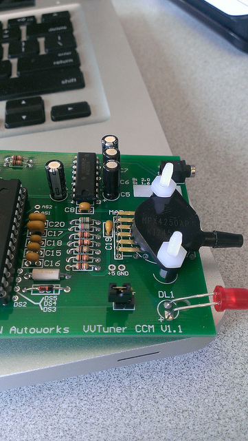
IMAG0571 by Gorillazfan, on Flickr
Should it be like this?
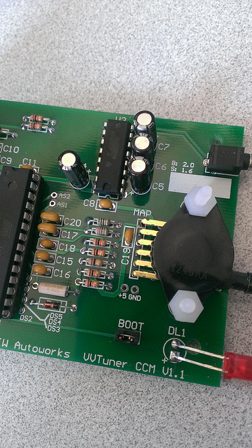
IMAG0570 by Gorillazfan, on Flickr
As it was found
IMAG0571 by Gorillazfan, on Flickr
Should it be like this?
IMAG0570 by Gorillazfan, on Flickr
Reply
0
0
Thread Starter
Senior Member
iTrader: (1)
Joined: May 2010
Posts: 581
Total Cats: 8
From: Harrisburg, Pa
Ok. Well I found a thread on mnet that the guy had to change something in the megasquirt to get it to start. I'm going to check voltage out of pins one and two later. Also we were thinking it could be that big centiped looking thing
Reply
0
0
Thread Starter
Senior Member
iTrader: (1)
Joined: May 2010
Posts: 581
Total Cats: 8
From: Harrisburg, Pa
It gives literally nothing. It shows nothing when cranking and won't save. So I figure I f'd up the board somehow. Everything looks ok and that caterpillar thing is like 0.80$ so I can afford to replace it
Reply
0
0
it's gotta be how you wired it.
Are you just tapped into the CMP/CKP or are you going into the VVTuner then back to the MS?
can you take pics of the harness and where you took your signals from?
this is an 01 with factory VVT?
yes, they have a diypnp for 01-05 now.
Are you just tapped into the CMP/CKP or are you going into the VVTuner then back to the MS?
can you take pics of the harness and where you took your signals from?
this is an 01 with factory VVT?
yes, they have a diypnp for 01-05 now.
Reply
0
0


