vvt tuner wiring help!
 04-16-2013, 03:03 PM
#41
Senior Member
Thread Starter
iTrader: (1)
Join Date: May 2010
Location: Harrisburg, Pa
Posts: 581
Total Cats: 8
Yes I can take pics. Yes 01 with factory vvt.
It goes crank sensor (ckp) to pin 4. Then pin 2 wired to 3Y. Not tapped. I removed the taps because diy told me to, to be sure I had a viable signal. I have the cam sensor (cmp) to pin 3 and pin 1 to 3V
It goes crank sensor (ckp) to pin 4. Then pin 2 wired to 3Y. Not tapped. I removed the taps because diy told me to, to be sure I had a viable signal. I have the cam sensor (cmp) to pin 3 and pin 1 to 3V

Reply
 0
0

0
04-16-2013, 05:16 PM
#47
Senior Member
Thread Starter
iTrader: (1)
Join Date: May 2010
Location: Harrisburg, Pa
Posts: 581
Total Cats: 8
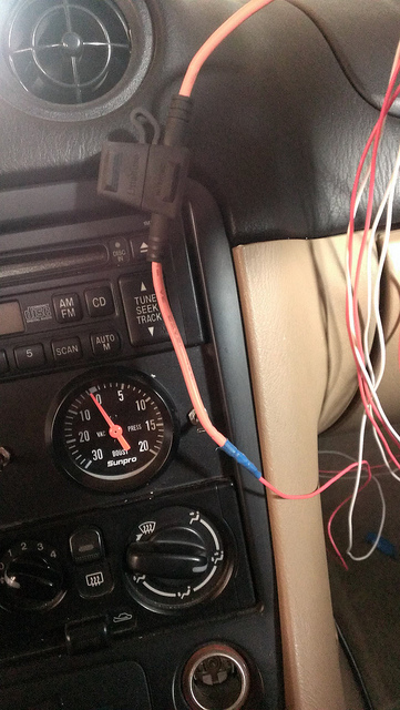
Ok here is the crank signal (purple white to white), OCV 12v in (yellow w/blue heat shrink), and OCV input (white to purple yellow)
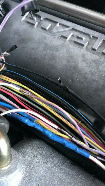
IMAG0579 by Gorillazfan, on Flickr
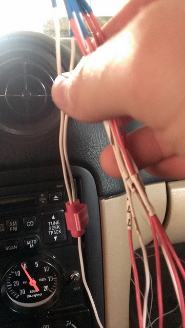
Here is the cam shaft signal
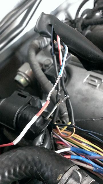
IMAG0576_BURST002_COVER by Gorillazfan, on Flickr
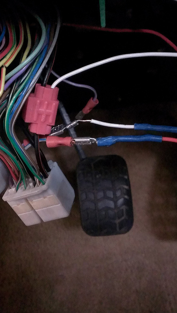
Here is all the garbage I disconnected (cmp, ckp to ecu, 12v into OCV, OCV input)
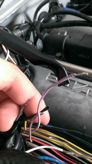
IMAG0577 by Gorillazfan, on Flickr
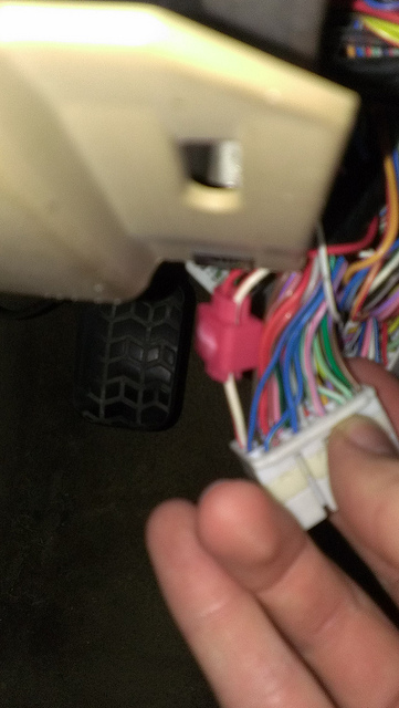
Here is my connector
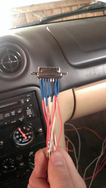
IMAG0583 by Gorillazfan, on Flickr
5amp fuse in my power line
IMAG0584 by Gorillazfan, on Flickr
Grounds tied together
IMAG0585 by Gorillazfan, on Flickr
Power
IMAG0588 by Gorillazfan, on Flickr
Ground and ckp and cmp back into the ecu
IMAG0590 by Gorillazfan, on Flickr
IMAG0579 by Gorillazfan, on Flickr
Here is the cam shaft signal
IMAG0576_BURST002_COVER by Gorillazfan, on Flickr
Here is all the garbage I disconnected (cmp, ckp to ecu, 12v into OCV, OCV input)
IMAG0577 by Gorillazfan, on Flickr
Here is my connector
IMAG0583 by Gorillazfan, on Flickr
5amp fuse in my power line
IMAG0584 by Gorillazfan, on Flickr
Grounds tied together
IMAG0585 by Gorillazfan, on Flickr
Power
IMAG0588 by Gorillazfan, on Flickr
Ground and ckp and cmp back into the ecu
IMAG0590 by Gorillazfan, on Flickr
Reply
0
0
04-16-2013, 05:42 PM
#48
Senior Member
Thread Starter
iTrader: (1)
Join Date: May 2010
Location: Harrisburg, Pa
Posts: 581
Total Cats: 8
Here's a megalog because it wont composite log during cranking with vvt's attached
Edity edit:
In my one picture you can see my quick connect crap things. I did this because I was hoping to leave the wires soldered together so I can switch and unplug, which I will have to do once a year for emissions. Thats also why I originally just tapped the wires and hoped I could share the signal.
Reply
0
0
04-17-2013, 03:38 PM
#50
Senior Member
Thread Starter
iTrader: (1)
Join Date: May 2010
Location: Harrisburg, Pa
Posts: 581
Total Cats: 8
I put the car back to a drivable state last night (where I have the sensors shared). I tried starting it and it of course did not start(with vvt attached). Is it possible that something is internally damaged despite still powering up and connecting with my pc?
Reply
0
0
04-17-2013, 07:44 PM
#51
Senior Member
Thread Starter
iTrader: (1)
Join Date: May 2010
Location: Harrisburg, Pa
Posts: 581
Total Cats: 8
I have more questions like did I fubar my OCV. So Ben told me to measure voltage at pin 8 and 15. With the ocv unplugged I got 1.25-1.75v at pin 8. At pin 15 I got 12.3v.
When I plugged it in I got no volts from either.
I then tested resistance across the ocv. I swear I saw it change but could not get it to do it again. Does no resistance mean I broke it?
Edity edit: I'm not sure my ammeter goes low enough to measure resistance. Or there is an issue with it. It never drops below one and the lowest setting for measuring ohm's is 200
Last edited by gorillazfan1023; 04-17-2013 at 09:17 PM.
Reply
0
0
04-19-2013, 04:33 PM
#53
Senior Member
Thread Starter
iTrader: (1)
Join Date: May 2010
Location: Harrisburg, Pa
Posts: 581
Total Cats: 8
Ok I'm back to thinking the box is broke or something. I measured resistance on the OCV today with a different multimeter and it was around 8.0 ohms and I believe its supposes to be ~7.5ohms
Reply
0
0
04-20-2013, 02:59 PM
#58
Boost Czar


iTrader: (62)
Join Date: May 2005
Location: Chantilly, VA
Posts: 79,499
Total Cats: 4,080
Here bro.
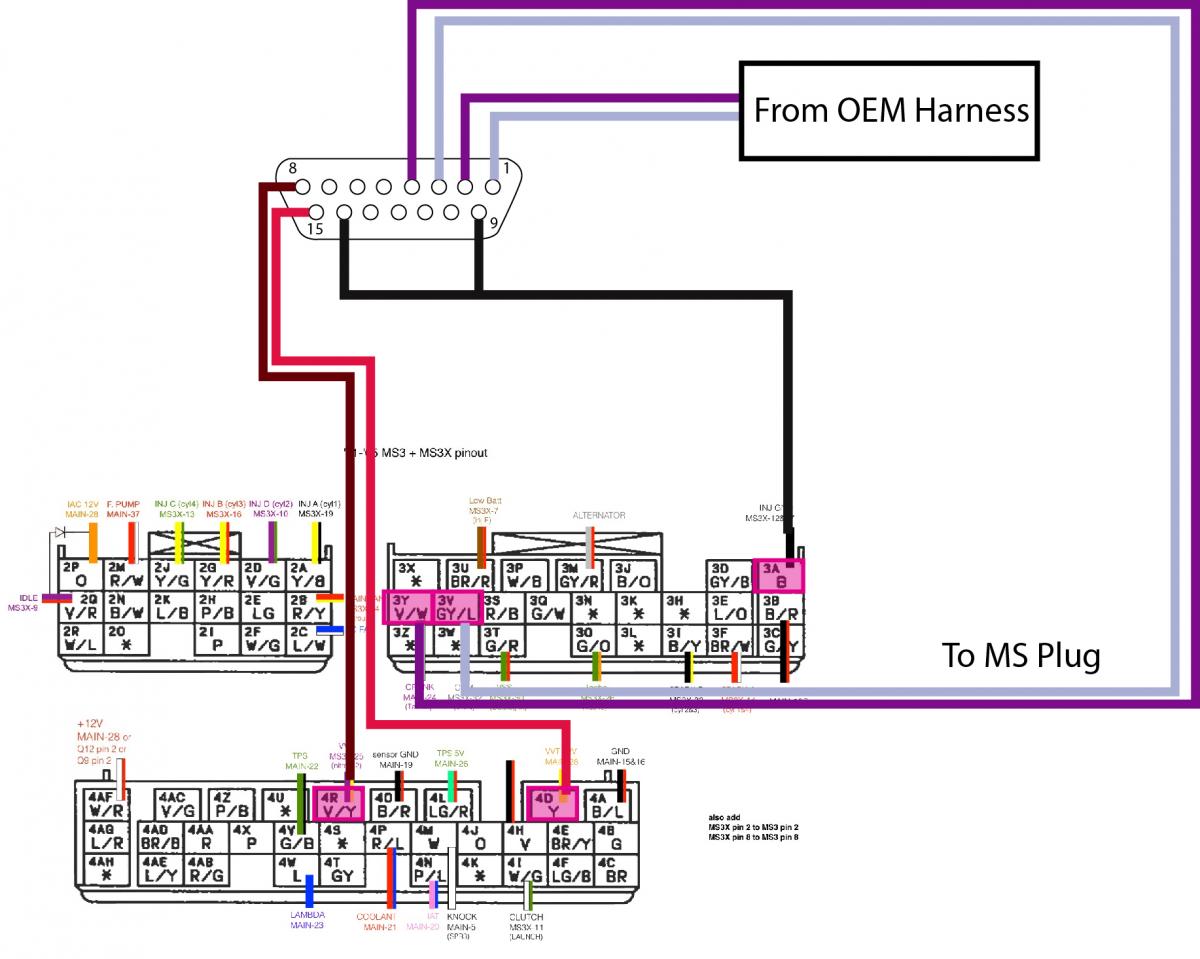
Pin 1 - CUT from OEM Harness, GY/L wire, 3V
Pin 2 - CUT from OEM Harness, V/W wire, 3Y
Pin 3 - Wire to the ECU side of the cut wire, GY/L, 3V
Pin 4 - Wire to the ECU side of the cut wire, V/W, 3Y
Pin 8 - To V/R wire, 4R
Pin 15 - To Y wire, 4D
Pins 14 & 9, to B wire, 3A
Pin 1 - CUT from OEM Harness, GY/L wire, 3V
Pin 2 - CUT from OEM Harness, V/W wire, 3Y
Pin 3 - Wire to the ECU side of the cut wire, GY/L, 3V
Pin 4 - Wire to the ECU side of the cut wire, V/W, 3Y
Pin 8 - To V/R wire, 4R
Pin 15 - To Y wire, 4D
Pins 14 & 9, to B wire, 3A
Reply
0
0
04-20-2013, 09:13 PM
#59
Senior Member
Thread Starter
iTrader: (1)
Join Date: May 2010
Location: Harrisburg, Pa
Posts: 581
Total Cats: 8
Here bro.
Pin 1 - CUT from OEM Harness, GY/L wire, 3V
Pin 2 - CUT from OEM Harness, V/W wire, 3Y
Pin 3 - Wire to the ECU side of the cut wire, GY/L, 3V
Pin 4 - Wire to the ECU side of the cut wire, V/W, 3Y
Pin 8 - To V/R wire, 4R
Pin 15 - To Y wire, 4D
Pins 14 & 9, to B wire, 3A
Pin 1 - CUT from OEM Harness, GY/L wire, 3V
Pin 2 - CUT from OEM Harness, V/W wire, 3Y
Pin 3 - Wire to the ECU side of the cut wire, GY/L, 3V
Pin 4 - Wire to the ECU side of the cut wire, V/W, 3Y
Pin 8 - To V/R wire, 4R
Pin 15 - To Y wire, 4D
Pins 14 & 9, to B wire, 3A
Reply
0
0
04-20-2013, 10:11 PM
#60
Senior Member
Thread Starter
iTrader: (1)
Join Date: May 2010
Location: Harrisburg, Pa
Posts: 581
Total Cats: 8
Here's a really stupid question. On you're drawing you have pin 1 oriented so it's at the right side. Is that just how you drew it? Because looking at my connector, from the side the wires go into. Its number 1-8. 1 being on the very left. I assumed the numbers corresponded to the numbers on the connector. However looking at diy's drawing they also have it oriented the same way you do.
Also my unit is plug and play so I'm not sure whats mean by to MS. because my plugs to my oem ecu are the same as the MS. And by "from OEM harness" do you mean from the sensor end of the oem harness or from the ecu of the oem wiring harness.
Clearly the issue is megasquirt isn't getting a crank or cam signal and therefore will not fire when cranking.
If I understand this correctly it should be.
3Y cut in half. The sensor half to pin 4, the ecu half to pin 2
3V cut in half. The sensor half to pin 3, the ecu half to pin 1
That's assuming I have all of the other wires correct. ( I know I do) I get proper voltages across pins 8 and 15 and good resistance across the OCV.
Heres what I've tried;
Sensors shared:
pin 4 tapped to 3Y
pin 3 tapped to 3V
I haven't tried flipping these wires yet, but I will. Though I'm under the impression that I have to change a resistor pull up on the megasquirt.
Pass through:
CKP sensor signal wire direct to pin 4
CMP sensor signal wire direct to pin 3
Pin 2 directly into 3Y
Pin 1 directly into 3V
In pass through I've also tried switching pin 2 into 3V and pin 1 into 3Y to be sure I didn't have it flipped.
In pass through I've also tried
switching CKP sensor directly into pin 2
switching CMP sensor directly into pin 1
Pin 4 directly to 3Y
Pin 3 directly to 3V
I also tried switching pin 4 directly to 3V and pin 3 directly to 3Y
Last edited by gorillazfan1023; 04-20-2013 at 11:22 PM.
Reply
0
0


