

brake duct air entry 3D printing

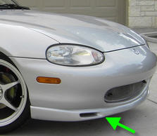

will that little hole move enough air to cool the brakes?
__________________
OG Racing
Your Source For Motorsports Safety Equipment
WWW.OGRACING.COM
800.934.9112
703.430.3303
info@ogracing.com
OG Racing
Your Source For Motorsports Safety Equipment
WWW.OGRACING.COM
800.934.9112
703.430.3303
info@ogracing.com
Reply
 0
0

0

With stock plastic in place I would rather make ducts from the one inch gap below the radiator ending in a hose attachments poking through the sides of OEM undertray just in front of the steering rack.
I have made one rough paper mockup and it looks possible, for someone who can channel energy in the right direction.
No extra opening in the front
Very short hoses
Foam strip below the rad replaced with something useful.
Folding thin aluminum and some tape would do it...
So why haven't I done it yet...
Reply
0
0

Measure the hole to find out.. 3" hose has ~7 sq. in. area, 2.5" hose ~5 sq. in.
Keep in mind that an opening low and to the side of the bumper like that, especially without a splitter below it to build pressure near the inlet opening, will be less effective/efficient by some percentage. I'd probably want that opening to be ~1.5x the area of the hose given its location.
-Ryan
Keep in mind that an opening low and to the side of the bumper like that, especially without a splitter below it to build pressure near the inlet opening, will be less effective/efficient by some percentage. I'd probably want that opening to be ~1.5x the area of the hose given its location.
-Ryan

Reply
0
0

I was thinking of making an insert for the GV lip NA brake duct if I ever get around to it.
Pass made some good points. Figure out the cross sectional area of that inlet first. If it is adequate the easiest way would be a digitizing arm get the CAD envelope would be easiest. Or use some can of foam to prototype it then reverse engineer it into CAD
Pass made some good points. Figure out the cross sectional area of that inlet first. If it is adequate the easiest way would be a digitizing arm get the CAD envelope would be easiest. Or use some can of foam to prototype it then reverse engineer it into CAD
Reply
0
0

IMO, no. If you're going to hamstring the ducting by feeding it through tiny holes, why bother at all? I get plenty of people asking me how to attach brake duct hose to the R-package inlets, and I tell them not to. If you want effective ducting, run dedicated holes in the bumper or route it alongside the radiator (inboard of the undertray) and attach it to the corners of the mouth.
Reply
0
0
Elite Member

Joined: Mar 2007
Posts: 5,306
Total Cats: 888
From: Santa Clara, CA
IMO, no. If you're going to hamstring the ducting by feeding it through tiny holes, why bother at all? I get plenty of people asking me how to attach brake duct hose to the R-package inlets, and I tell them not to. If you want effective ducting, run dedicated holes in the bumper or route it alongside the radiator (inboard of the undertray) and attach it to the corners of the mouth.
--Ian
Reply
0
0

Senior Member
Joined: May 2011
Posts: 638
Total Cats: 76
not an effective location for brake ducts. At that point in the bumper the air is already headed nearly perpendicularly to the direction that you want.
IE, laminar flow Laminar flow - Wikipedia, the free encyclopedia
IE, laminar flow Laminar flow - Wikipedia, the free encyclopedia
Reply
0
0
not an effective location for brake ducts. At that point in the bumper the air is already headed nearly perpendicularly to the direction that you want.
IE, laminar flow Laminar flow - Wikipedia, the free encyclopedia
IE, laminar flow Laminar flow - Wikipedia, the free encyclopedia
Reply
0
0
Senior Member
Joined: May 2011
Posts: 638
Total Cats: 76
This is what i've been told by others and then confirmed with my own research. YMMV i guess?
Reply
0
0
I don't think it works like that. Air is headed in that direction because of the nose of hte car is pushing it aside and around the car. Therefor the air is already headed in a direction perpendicular to the hole.
This is what i've been told by others and then confirmed with my own research. YMMV i guess?
This is what i've been told by others and then confirmed with my own research. YMMV i guess?
Reply
0
0

Assuming the cross section is adequate the easiest and cheapest way to fabricate these would be similar to how subwoofer boxes are made. You can use that process to make a plug, create a split mold, and then make the final part out of fiberglass.
I have come to the conclusion that the FDM printing available to most consumers sucks at making thin walled ducts. SLS printing thin walled parts works a lot better but it is expensive.
I have come to the conclusion that the FDM printing available to most consumers sucks at making thin walled ducts. SLS printing thin walled parts works a lot better but it is expensive.
Reply
0
0

Junior Member
Joined: Feb 2012
Posts: 60
Total Cats: 21
From: near Ottawa Ontario Canada
We did the Fog Light brake duct solution on our NB1 (the 99 racer). It worked great for us in the great white north�
All prices are by memory but you get the idea... total ~ $240 with shipping from various suppliers.
$20 ebay fog light rings,
$20 Aircraft Spruce 2 1/2" duct flanges (an Emilio recommended supplier), ALUMINUM FLANGES FOR DUCTING from Aircraft Spruce
$30-60 2 1/2" air ducting � a wide range in prices based on temp resistance and quality...
$125 Aluminum brake duct backing plates from ISC, Miata power train
$20 hose clamps, wire ties, screws & nuts, aluminum strip, other stuff.
I merged ideas from 949 (brake cooling duct running - attaching it to the sway bar and end links), ISC, plus I like the fog light rings to keep everything clean. Alternately, forward facing ducts in the rad air inlet should also work�
ISC Brake ducts:
Like � they direct the cooling air at the center of the disk, wheel bearing and the inner pad / caliper. The design forces cold air into the center of the disk for maximum vane effectiveness. Inside face of the disk is not covered so it benefits from any additional air that happens to pass by the 9� 6UL wheel.
Don�t like � the lower backing plate rubs on the lower ball joint boot. I reshaped this for more clearance and had it tig welded. You also have to cut off the wheel speed sensor boss from the spindle so no ABS. Our race regs do not allow ABS so not really an issue for us.
Effectiveness � on a typical summer day for us (75-80 F) we had to tape off about 1/3 of the air inlet as the front brakes were running too cool vs the rear (without the tape we had to continue to adjust the bias throughout the race since the front brakes never really heated up however the rear brakes did changing the front rear balance). At about 95 F or so, it worked fine without tape.
The car has stock NB1 brakes & PF97 pads. No inner fender liners, no brake backing plates front or rear.
Previously configuration WITHOUT air ducts - The front rotors would glow red on one or more braking zones per lap (depending on track). Calipers got hot enough to discolor 750F caliper paint at the outer pad. Engine near stock (RB header + 2 1/2� exhaust).
The fog light entry and 2 �� ducting worked for us, with more HP & larger brakes better ducting & more air flow may be needed.
Reply
0
0

Thread Starter
Elite Member
Joined: Jul 2005
Posts: 6,420
Total Cats: 84
The slots in the pic in my first post are 6x1". That's 1.5x the area of 2" brake ducts.
I agree foglight holes would be great but I use 1 already for my oil cooler. It's a small Setrab but drops temps 7*C in a 5 mile steep slow mountain road run.
I agree foglight holes would be great but I use 1 already for my oil cooler. It's a small Setrab but drops temps 7*C in a 5 mile steep slow mountain road run.
Reply
0
0
With a splitter I bet you would get good airflow through there. Without one I think it needs some testing to determine it's worth the effort. There's not much at that location preventing the air from going under the bumper vs through that hole.
Reply
0
0

Thread
Thread Starter
Forum
Replies
Last Post


