When you click on links to various merchants on this site and make a purchase, this can result in this site earning a commission. Affiliate programs and affiliations include, but are not limited to, the eBay Partner Network.
Rywire / Moristech P12 PDM Power Distribution Module Review and Instructions
Figured this might be of interest to some of you. I posted some details in my build thread but I felt like this might deserve a thread of its own and there isn't much info available online for this unit. I am not associated with any of the companies (Moristech or Rywire), I just happen to love the product and paid full retail ($800) for the unit I am using.
It is essentially a solid state power, fuse and relay controller. You have 10 inputs (power or ground switched) and 12 outputs (15 amps continuous each and two can be combined for 30 amps). This has made the chassis wiring on my build very simple and easy to do. Rywire didn't supply an instruction manual, so there was a bit of experimenting on my end to figure out all the options and how exactly this thing works. I'm doing a simple write-up for them so they can provide instructions to customers in the future. There are other devices on the market similar to this, but I believe the P12 is the most affordable and probably the best value right now. They also have a P30 unit that is very similar but offers more outputs and higher amperage on those outputs.
Rywire offers a universal chassis harness that connects to the P12. I purchased this, but the chassis harness is designed for a much larger car than a miata. For anyone going down this path, I would recommend just buying the P12 and and using the connector kit it comes with. Then get some Tefzel wire from Prowireusa to simply make your own chassis harness. I went with Tefzel 16 gauge for the inputs and 14 gauge for the outputs and grounds.
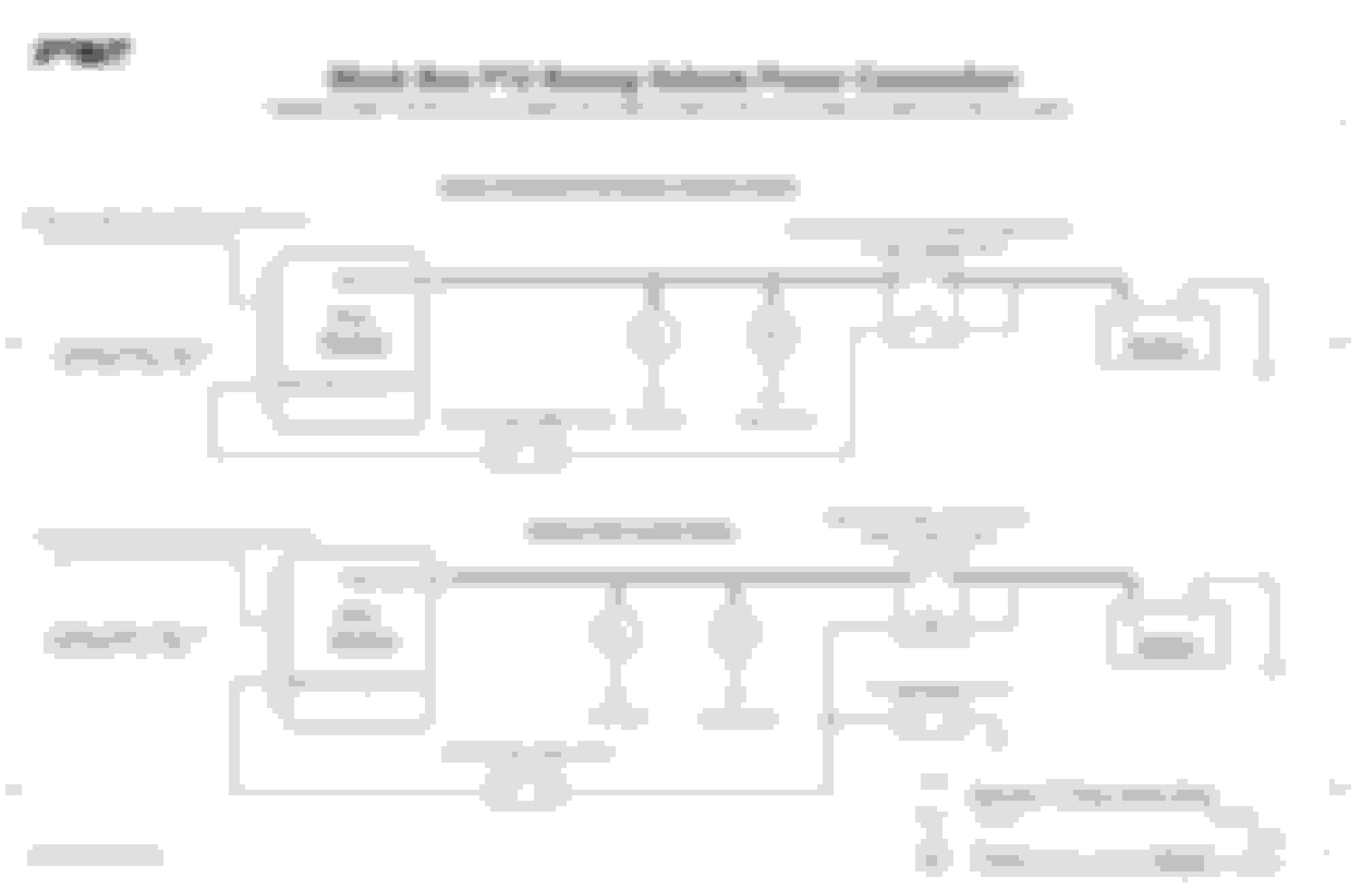
The P12 unit needs a few connections to power up and and connect to your computer.
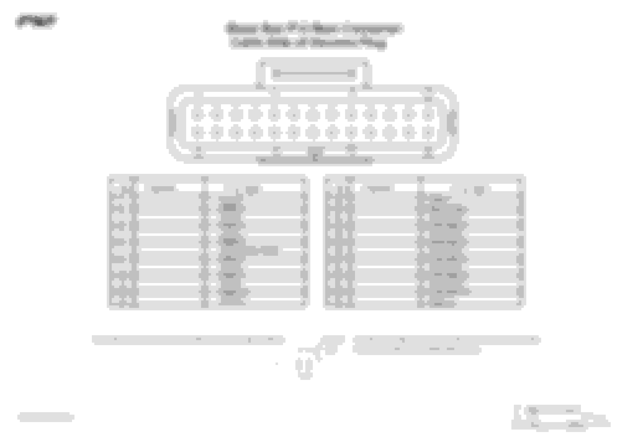
Top Stud on Unit: This needs to be supplied power with a high quality battery cable (ideally 4awg). This post provides the power to all of the output channels on the unit. Pin 15: This wire needs to be provided power (12v) to switch the unit on. Pins 3+11: These are the ground wires for the unit. Pins 16-25: These are the input switches. The unit is set up to default to ground switches, but can be configured to run powered switches as well. Pins 1, 2, 4, 5, 6, 8, 9, 10, 12, 13, 14, 26: These are the outputs and can be connected to anything you want to send power to. These can be combined to provide 30 amps to a fuel pump for example.
Here is the list of features from the manufacturer:
Features:
� 12 * 15 Amp continuous outputs.
� Outputs can be combined for higher output current.
� 100 Amp maximum total current recommended.
� Easy to use and understand software.
� Programmable output current and fuse reset time and
count.
� 10 Switch Inputs + Master Switch Input.
� Switch inputs can be connected to power, ground or
floating (3 state, center-off type switches).
� Fault indicator Output can drive a lamp or LED to indicate
output short circuit, open circuit or low battery voltage.
� Fault indicator output can alternatively be used as an
additional low current output.
� On board data logging to record battery voltage, total
current, individual output current, module temperature and
input switch voltage.
� Compatible with 24volt systems.
� Reveres battery protected and transient overvoltage
protected.
� Programmable functions including True, False, AND, OR,
Flash, Pulse Train, Toggle, Set/Reset to control such things
as Turning Indicators, Hazard and Emergency lights.
� Ideal for transmission brake staging or ‘bump’ control.
� Software displays live values of output currents, battery
voltage, switch status, function status and outputs/fuse
status.
� Compact Size. Main body: 123mm * 112mm * 33mm.
� Main and USB connectors are sealed with gold plated
terminals.
� Field upgradable to keep up to date with the latest software
and firmware.
� 1 year warranty.
Install was a breeze, simply connect your inputs and outputs and then configure what inputs control which outputs in the software. The unit even has options to control blinkers with timed flashes which is really nice and removes any need for external relays. I'm currently working on a write-up for using the software and will post that up shortly. For the connector pins, I used the tool below and it worked great.


 0
0


