When you click on links to various merchants on this site and make a purchase, this can result in this site earning a commission. Affiliate programs and affiliations include, but are not limited to, the eBay Partner Network.
BTW, consider of throwing some methanol in the mix too.
Yes certainly going to have a bit of a play with the mix once it is up and running. Going to run atleast 5 or 10% to start, just to keep the tank and lines free.
Might strengthen the mix if we find it has benefits for this setup.
I think that I sent a mixed message. I think that using WI is a great idea in your case. I had the same thought a couple years ago when I didn't have e85 available. In fact I still have all the WI parts in a box somewhere.
I also think that for where you are and your goal of decreasing the IATs to below 40C, it may not meet the requirements.
Nothing left but to do the experiment! If you were in the US, I'd send you the parts to test.
Thanks mate I appreciate the thought.
I'm with you on sub 40degC IATs on a hot day most likely being out of reach with WI.
What I hope is that the in cylinder benefits of WI - effective octane increase, slower and cooler combustion allow for timing to be advanced even if the IAT is higher than I initially would like.
I have a buyer for my old sc setup and I still have my old Torsen to sell so plan is to get the WI ordered next month.
What I really want is a PWM system so the water / meth ratio to fuel can be kept linear through the rev range, unlike the systems that operate either as a on / off or boost referenced.
The Aquamist HFS3 sytem fits the bill, but it is possible that I can put something together using my ECU and a PWM valve.
Need to see what inputs / outputs I have available and what the cost difference is.
Been a little while since I updated, progress has been a bit slower than I had wanted for a few reasons but hopefully over the next month or so I can get the the water injection on the car.
I was really just enjoying driving the car at the end of the summer rather than having it off the road fiddling with it. Went to a few shows, went on some nice drives and did a private trackday at a local sprint track, Curborough. It was mostly wet all day but I did get a dry run in, link of a video from the day below.
Then I crashed it on a cold damp morning. Wasn't even pushing it, got caught out on some mud on a damp country road and ended up going up a curb sideways at about 50mph. Luckily the car didn't flip but it broke 3 wheels, bent the wishbones, subframes and one of my front coilovers, broke the lh rear hub in two and to add insult to injury I went sideways through a sign, damaging the door and rear qtr just in front of the wheelarch. The car looked a right state lying in the road on its belly with broken wheels, but luckily the damage proved to be relatively limited.
I rebuilt the suspension with new arms, hubs and front subframe and new coilovers (Meister R Clubrace). Repaired a small bit of damage to the lh side floor pan rail and replaced the stainless steel frame rails that seemed to have done a very good job protecting the underside of the car during the crash. While the car was off the road I also made some door bars, which I had wanted to do for a while.
I got the car back on its wheels and went to the alignment shop. Good news is the car itself is straight still. However, I didn't replace the rear subframe during the repair and that proved to be a bit of an error. It measured up ok with my tape measure, but under more accurate measurement it turned out it had been knocked a bit. We still got a decent alignment in the car, but it has limited the range of camber adjustment in the rear. I have found a decent subframe now and I will swap it out at some point to correct that. I would like to get some track driving under my belt with the new coilovers first before swapping and another alignment so we can tweak the setup if required.
I got the car home and set about repairing the body. Swapped the door out for a half decent replacement and then tried and failed to pull the dent out the rear qtr. In the end I had to cut the dent out and weld in a new panel. It went alright. I hadn't done any body welding like this so it was certainly nerve wracking but the result is ok for now. I'm actually pretty happy with the metal work but painting in the cold winter is a total PITA. There are some imperfections in the paint but it looks presentable and nothing that a quick flat and brush over won't fix when the weather warms up in spring.
Back on its wheels but body still to do. Doesn't look to bad really but was too stretched and deformed to just pull out. Looks good from underneath though! All nice and straight again. No turning back now! Welding complete The finished job - ok for now
Anyway that sort of put a bit of a dampener on the water injection plans as it was not a cheap fix, but I'm back on it now! Luckily or not I ordered a lot of the WI parts before the crash and I was waiting for them to arrive when the accident happened. So the plan for the WI is as follows:
> 5x nozzles - 1x 140cc nozzle pre sc, 4x 85cc nozzles across the exit of the chargecooler. This gives me the the ability to run a water / meth to fuel ratio of up to 25%. I hope the pre sc nozzle will help just take a bit of an edge off the temps while keeping the charge cooler efficiency high and also help cool the sc. The nozzles after the chargecooler will then inject the majority of the water to cool the air charge a bit further before working its magic in the cylinders allowing me to add some timing without pinging.
> PWM valve to control the flow, controlled by my MS2. I was going to highjack the boost valve control function on my ECU but this was not ideal, as it did duty by TPS vs RPM. I really wanted MAP vs RPM for ease of tuning, but my ECU didn't have a generic PWM output to do this. I was looking at upgrading to MS3X, but then I found the Tiny I/Ox board from Jean. The 9 additional ADC and 2x generic PWM outputs mean I will be able to run the whole show from my MS2 now with MAP vs RPM for the valve. Well chuffed with that.
> AEM failsafe flow gauge to ensure safety. It maps flow rate from its flow sensor against valve or pump duty and you can set cutoff points for abnormal flow rates at these duties, safe guarding against lack of flow (blocked nozzle) or too much flow (burst pipe). It has outputs to send a signal to the ECU in the event abnormal flow. I will use this to deactivate the WI fuel and spark mapping in the ECU, reverting it back to the non WI map. It also has a 0-5v output for water flow rate, which I will feed into the MS2. This will allow me to be able create a water / fuel ratio channel and accurately tune to my desired water / fuel ratio when I am setting it up.
Really the only bits I need to sort now are the tank and the routing of the pipework on the engine. I have settled on making a stainless steel feed rail next to my fuel rail like the picture below, it looks neat and inkeeping with the rest of the engine bay. The PWM valve and flow sensor I will mount on the chassis leg somewhere and then route the water feed under the car along the fuel lines. The tank I think I am going to fabricate myself. from stainless. I can't really find anything I like off the shelf that fits efficiently in the boot space I have in mind, has the right capacity (approx 10L - I estimate this is what I would go through at a 10-15% ratio on a normal trackday) and has the right anti surge characteristics to work properly at lower fluid levels during hard driving. Using stainless means I can use higher methanol % in the future if I want to, whereas using aluminium would likely create corrosion issues.
Got to love MS Paint :-)
Anyway fabrication will start again very soon so I won't have to resort to MS Paint, stay tuned
Made a start on the tank this afternoon using a bit of CAD to mock it up. It fits nicely in the lh side boot wheelarch cavity, so doesn't really intrude into the boot too much. The main section has a volume of around 9.3litres and it features a smaller lower section at the back of the tank that will have the pickup and low level sensor in it. The lower section should ensure that there is water available to the pickup and reduces surge of the water by the pickup under braking, acceleration and turning. It might be a bit OTT, really I will only be using the water under hard acceleration so the water should always be against the back of the tank when required, but as I am making the tank myself anyway and the space allows it I may as well do it. It should also give me more stable readings from the level sensor and allow me to use all of the capacity of the main tank above.
CAD tank in place. Not 100% sure on pump placement yet. Underside of the tank with the lower section to prevent surge
Just need to think about the pump placement. Ideally I want it as low as possible, but I don't think it will fit under the tank.
That's a lot of work, nicely done to keep it on the road. You won't see as much of that on this site. In the US, Miatas are cheap enough that it doesn't make as much sense to do that intense of a repair. The follow-on being that cars that have that much repair cost spent will not see the return when sold.
It's probably too late, but consider an injection nozzle upstream of the supercharger. It's supposed to provide the greatest benefit. It allows the water the maximum amount of time in the intake tract to cool the charge, cools the blower, and helps with rotor sealing (efficiency). I started another project, so I have never had a chance to test myself, but it's common in other autorotor supercharged cars. The other common modification is a huge, high flow, throttle body and intake tract. This is due to the fact that it is very difficult to "pull" air, an equal sized restriction across both sides of an air pump will have non equal outcomes.
Ignore the above comment about the upstream injector. I am on mobile and just noticed that you are terminating the line at the intake in the photo.
I would think hard about whether you have the flow to maintain the same pressure across the entire "water rail". You may want to split the feed to both ends, or some other strategy to help distribute the water in a reliable way.
I nozzles being so close to the cylinders... doesn't give me confidence that they will be measurable (no change in a sensor for you ecu to use- so you will be relying on whatever changes you make can be sustainable at all times) and effective (time for the air vaporize into the intake air before combustion), but I could be wrong.
here is the final incarnation.
I have no idea as to what led me to split the subject like that. I really should have brought everything together in one thread.
Anyway, such a setup allows me to use the full width of the trunk, as well as a nice, correct placement for the pump.
That's a lot of work, nicely done to keep it on the road. You won't see as much of that on this site. In the US, Miatas are cheap enough that it doesn't make as much sense to do that intense of a repair. The follow-on being that cars that have that much repair cost spent will not see the return when sold.
It's probably too late, but consider an injection nozzle upstream of the supercharger. It's supposed to provide the greatest benefit. It allows the water the maximum amount of time in the intake tract to cool the charge, cools the blower, and helps with rotor sealing (efficiency). I started another project, so I have never had a chance to test myself, but it's common in other autorotor supercharged cars. The other common modification is a huge, high flow, throttle body and intake tract. This is due to the fact that it is very difficult to "pull" air, an equal sized restriction across both sides of an air pump will have non equal outcomes.
Thanks mate, the repair wasn't too bad. Most of the work / expense was rebuilding the suspension and to be honest it had had 4 years of commuting and trackdays on it. It was in need of going through. Once I knew the chassis was straight the reasonably localised body repair made far more sense than replacing the shell or buying another car to swap the driveline into.
Yeah I actually had a similar thought about the water rail or whatever I call it :-) and actually I have made changes to my nozzle plans too. So I will be using the pre sc nozzle - as you say there are well documented benefits of spraying water into the back of an sc. The temps in the sc are high enough to vaporise the water, putting high latent heat of vaporisation of water to the best use. It should also help take heat out of the sc itself and probably oil temps too (oil fed supercharger). The reason I don't want to go too mad on the pre sc nozzle size is due to the chargecooler. If too much water is injected a lot of it will likely condense out the air in the cooler. This could give me running issues and a lot of water may not actually get to the cylinders in usable small droplets. I just want to inject a bit to take the edge off the temps, seal and cool the rotors.
Instead of injecting right after the charge cooler just before the AIT sensor I am actually going to put the nozzles just in front of the injectors, after the AIT sensor and in each port of the manifold. I've got a few reasons for doing this. From the research I have been doing one of the key considerations when spraying only water is keeping the water in suspension in the air to get it actually into the cylinders where it can perform its cooling properly, particularly where AITs are lowish (intercooled setups like mine), as the water can condense into large droplets on surfaces inside the induction system. In this respect methanol performs better as it has a lower flashpoint so stays in the air stream more easily - I think this is one of the reasons on dry flow designed manifolds people often see better results using 50/50 or higher mixtures of meth. From where I had my nozzles planned initially on the charge cooler outlet the water would first be battered into a steeply angled part of the manifold, before another sharp turn into the ports, before then going down the ports into the cylinders. I think it is likely this path at temps in the 50-60degC range would result in poor atomisation of the water and unreliable water % making it to the cylinders. Injecting behind the injectors in the ports does two things - ensures as even as possible water % in every cylinder and best quality of water into the cylinders (small atomised droplets) in order to best cool the combustion process and protect against detonation.
However, the setup above probably would not result in a significant, if any affect on the AITs my sensor sees, but I'm not convinced that it is as important anymore. Meth seems to do a better job of cooling the air charge in the induction tract from what I have read so far. It has the lower flashpoint, evaporating more easily than water and so taking heat out of the charge more readily (even though it's latent heat of vaporisation is less than water) Lower AITs mean higher charge density, and lower combustion temperatures resulting in a lower likelihood of knock. Water has a better cooling effect in extreme temperatures (in cylinder combustion) because of the higher latent heat of vaporisation, and so a better ability to reduce knock when delivered to the cylinder correctly (small atomised droplets to allow full vaporisation during combustion).
The reason my ECU pulls timing and reduces power at higher AITs is to reduce the risk of knock. Injecting well atomised water into the combustion chamber should do a fantastic job of preventing this, and should mean there is no need for my ECU to pull timing anymore during WI at the max temps I see on a hot day - around 60degC. What I want is my ECU to pull timing as normal with WI off, but give me more headroom when it is on, and I have come up with a way to do this in my ECU. Basically I am going to install a transistor and an extra resistor in parallel to the existing AIT sensor bias resistor. When WI is on the transistor will switch on and the second resistor in parallel will skew the AIT voltage the ECU sees by whatever I want it to. I will probably start at just 10-15degC. That should keep me out retardation temps normally under WI, but if AITs really did get excessive (charge cooler pump failure etc) it still retards timing, just at a higher temp.
Tuning wise my intention is to get the water % setup at 10-15% between say 8-14psi across the rev range, blending the water in from say 6psi. I am then going to back the fuel out slowly to 12.5-13AFR in these areas - this seems to be the max power AFR for gasoline from what I have read so seems to be a good place to start (something about reduced CO and increased CO2 formation in the second stage of combustion and an increase in energy release due to this). Once fuelling is setup I will start to add timing. I'm not going to go too mad here, I want to be able to go flat out on track in the summer for decent length sessions safely. I will happily trade a few hp for that safety margin.
That's the plan until next week anyway :-) One trend I have really seen with WI / meth injection is that there are all types of ways of going about it on a multitude of different engine setups. Different mixtures, different fuelling, different timing, turbo / sc / intercooled / non intercooled , ECU, WI control, nozzle sizes, qty and position and every choice / setting seems to effect something else. Hopefully what I have written above isn't a load of total bollocks, I have 0 practical experience of WI but I've got technical papers, forum threads and builds coming out my ears! Once I have it setup running water I will have a play with adding meth. I want to do some trackdays on the water only just to see what tank capacity is like.
here is the final incarnation.
I have no idea as to what led me to split the subject like that. I really should have brought everything together in one thread.
Anyway, such a setup allows me to use the full width of the trunk, as well as a nice, correct placement for the pump.
Just my 2 cents.
Cheers for that - I have already had a snoop through the first thread before - great work. I feel blessed with the decent petrol we get over here in the UK :-)
I will have a look through your second thread too.
I like your multi tank setup, really good use of the space and excellently engineered. I may well do something similar if I find the single 10L side tank falls a bit short.
Interesting that you are port injecting after the AIT sensor (I plan to do the same, see obnoxiously long post above). How did you tune for the water? What AFRs and spark advance over just petrol / gasoline?
Hope everyone had a great Christmas, and Happy New Year.
Managed to crack on a bit with the car today.
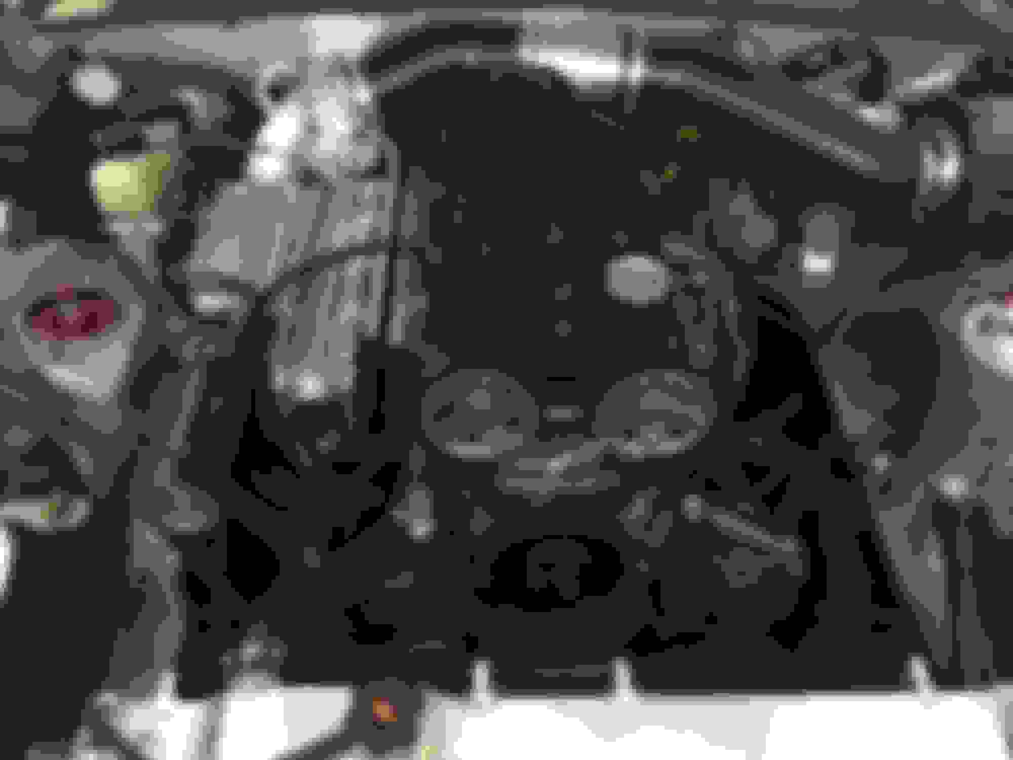
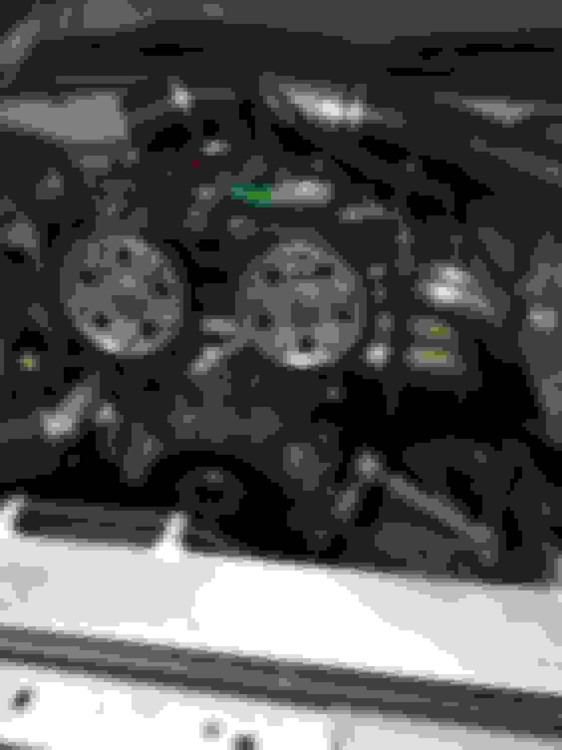
I removed the supercharger system from the engine so I can weld the nozzle bosses on the manifold. I managed to get two of them on today. Fitment is tight but there is room there to get the pipework to the nozzles. I will have to make a little bit of a change to the injector loom to allow me to rotate the injector plugs clear of the WI nozzles.
Two of the bosses welded onto the manifold runners. Fitment is tight but ok A sign from God?
While the car is off the road I am going to send the supercharger away to be inspected. I noticed last time I took the supercharger off the car there was a small amount of debris in the oil in the inlet and manifold. There was also a bit of light scoring in the supercharger case. At the time I thought maybe something had been through the back of it after the first install, so I cleaned everything out, new air filter and reinstalled it. I've taken it apart again and there is a small amount of debris in the manifold and inlet again. I have been through everything, looked in the head, checked the catch can and inlet / filter and no sign of anything. Its like little bits of metallic shavings - certainly not something I am going to chance now I know that whatever is being shaved is continuing to be shaved. I had noticed that the rear bearings were getting a bit rumbly also, it may well be related. Also the charger does seem to contribute to an increase in oil consumption and there is certainly a reasonable amount of oil in the intake. Another clue is if I cruise for a while (intake in vacuum) then get on the throttle often there is a puff of smoke. It only ever does it when I have been in vacuum for a while, and it is only at the very start of the throttle application. If you get on the throttle again soon after the first time you accelerate it doesn't puff. I think what is going on it the vacuum draws oil from the gear case through the seal, but there isn't sufficient air flow to suck it all into the cylinders and some of it sits in the manifold. When you then hit the throttle the increased air flow picks the oil up and pushes it into the cylinders, clearing out the manifold. If you stay in the throttle there is no vacuum so no more oil gets past the seal.
Anyway luckily after speaking with a contact of Dennis' contacts there is a place here in the UK I can send the unit to be inspected and that have spare parts and assembly tooling if required. Hopefully an issue will be found that can be resolved, as I am 100% sure the shavings are from the scoring on the case. I haven't noticed any drop in boost pressures, in fact they have been increasing to about 14.5psi in the cold weather (up from 13.5 in the summer) Hopefully new bearings and seals and we will be back in business.
I have also been playing around a bit with some ways to measure any performance increases (or decreases) with the WI, exhaust etc without having to spend loads on dyno time.
I got a 10Hz capable GPS receiver that will allow me to see power and torque figures in Tunerstudio, and also came across Virtual Dyno, which doesn't need the GPS, it just calculates from time and rpm (which makes life a bit simpler than faffing with the GPS receiver).
I plugged in a few of my previous datalogs into tunerstudio and a couple of them produced very very close representations of what I saw from my last dyno session, both in terms of peak whp but also the position and value of peak torque. Quite a few also produced figures that were way off - I think due to me normally testing stuff out on quiet but bumpy country roads. A lot of my 3rd gear pulls contain bits of wheelspin over these bumps that throw the power calculations out. I also plugged in one of the few logs I have from my old M45 setup. That showed power figures that I would expect also - I had that setup dynod at 182whp - the development of that setup over the years I had it hopefully bought me a few additional hp so I think virtual dyno is probably spot on. Red is the Autorotor, blue is the old M45.
If I actually produce logs taking into account Virtual Dyno's requirements - lack of wheelspin on the same bit of flat level road - I should be able to make pretty accurate comparisons from tuning and hardware changes.
What is also interesting from the plot above is that it was taken from a log where the ambient temperature was about 13degC, and did not have any MAT spark retard present. It shows the same power / torque curve that I saw on the dyno on the 30degC day. I thought that maybe the ECU was pulling timing at the top end on the dyno due to the MAT it was seeing, reducing the torque in those higher rpms and therefore the netting the lower peak hp than I expected on the new pulleys. The virtual dyno plot does not suggest this is the case. It shows that the torque is dropping off a bit without any MAT spark retard.
I think to net the expected gains from the pulleys I need to increase the flow capacity / volumetric efficiency of the engine / exhaust to maintain higher torque for longer in the rpm range. I have already measured pretty high back pressure in the exhaust at higher rpm and I am already planning to build a more suitably sized exhaust manifold. I will take a look at different back box options, as actually the car is pretty quiet at the moment exhaust wise - I have a bit of room to play with there flow / vs noise.
On the intake side there is some smoothing out inside the charge cooler and manifold that can be done pretty easily. I have also realised that I didn't really optimise the bit of headwork I did when I put my head together two or three years ago. I did smooth out the casting as it meets the valve seat machining on the long side of the port and a bit of unshrouding in the combustion chamber, but I didn't do anything on the short side. Now I have the sc system off I can feel the 'cliff edge' on the short side radius. There was some really interesting testing of the above mods on the BP4W head, see link below. Basically a bowl cleanup, short side radius and unshrouding gave just over a 4% increase in flow across valve openings up to 10mm over a stock BP4W. So I may well take the head off while I have the supercharger off and revisit the ports, maybe even some +1 intake valves as the linked investigation suggested further performance gains could be had with them (I will see - I want to see how much the sc and the machining costs for fitting the valves is first, I may leave them for another day). The added kicker is that if head flow can be increased, then manifold pressure will drop, lowering MATs with it.
Some good news from my supercharger rebuilder Pete today! There were some issues with it. It had been rebuilt at some point with the incorrect seals and bearings. The rotors were also slightly out of tolerance, not enough to touch at any point but still not right. The scoring is very light in the case and he says it will be absolutely fine. Great news and so glad that I got it rebuilt now. It would have most likely destroyed the bearings pretty quickly on any more trackdays. Hopefully should have that all back in a couple of weeks.
The WI nozzle ports on the inlet are almost done, just need to smooth them out a little, I will post a picture when I do that this weekend.
I have also started work on my exhaust manifold. Really happy so far, I have the top pipes in place and they are looking pretty simple to get down to the collector in the right order. Starting with a short length of 1 3/4" before stepping into 1 7/8 has worked well and is really useful as they slip fit over one another. You can mock things up without having to tack weld, just keeps it clean if you have to adjust something. Also I am not going to have to shrink the 1 3/4" to meet the exhaust port size. The flange I bought has a perfect 3mm step out of the port, and the 1 3/4" inside diameter is exactly the same as the circumference of the flange port.
The only thing will be that they will be about 5cm -15cm shorter than I would ideally like them. My optimum length of between 28 and 32" primaries puts the collector right in the tight spot between the gearbox bellhousing and the start of the trans tunnel. I was looking at making the routing longer in the engine bay, but I am conscious of having too much extremely hot metal near my intake and charge cooler reservoir, or also maybe notching the front subframe, but that would be a PITA. Also I don't want to get too complicated because there is an extremely high likelyhood I will bollocks it all up. As it is I think it is going to look really smart with optimised primary diameters and only slightly too short primaries that I think I could actually dial in retarding the exhaust cam slightly, if that makes a difference in the end.
I realised the reshaping of the tubes to meet the ports can change the angles at the other end and effect the runner geometry, so best to crush them to shape at the start once you have a reasonable idea of the angle and where they need to point. I did this in a bench vice, no high tech solutions here but it works well. Best to crush the pipe down to slightly smaller than the height of the port, then turn the pipe 90 deg and slightly crush the tube back, correcting the height and also nicely adjusting to match the semi circle ends of the port. It was also best to crush the pipe with the connecting pipe engaged on the other end, it kept it circular during the work. One of the pipes didn't form a nice uniform semicircle but it can be corrected using a suitably sized socket in the vice to open the rad back up.
I am going to redo cyl 4 bring it arching up higher which will help routing. But I have cyl 1 and 3 now pointing right where they need to, cyl 2 is a 45deg away from lining up. Once I have all four in line I will look at whether I cut my losses and add the collector at that point making a shorty style header, or try to go whole hog and try to squeeze 4x 1.875" tubes down past the gearbox. I need to research how the shortys work because I think I could add my collector at half my target primary length, at 15" to 16", and this might be quite helpful in boosting the rpms I want to without the difficulty and cost of squeezing all that pipe past the gearbox.
*update - definitely going with a shorty header design. Should help boost the upper rpms which is what I am after.
High tech solutions Correcting the radius But they come out pretty good Good fit up, will be easy to smooth out after welding Pointing in the right direction I am redoing cyl 4, bringing it up slightly higher which will help a little geometry wise.
Quality work, bravo! Is the tubing pre-bent, or do you have access in a bender?
Thanks very much I'm pretty excited to see how it comes out!
They are those prebent mandrel bends you can buy. I wish I hade a tube bender and a bandsaw, it would make life so much easier.
The top bends aren't too bad to work out, cyl 1 is 90deg, cyl 2 & 3 are 30deg followed by 135deg bends and cyl 4 will be a 45deg then 135deg.
It gets way trickier on the next set of bends because they are all 3D compound angles. The life saver has been having the tight slip fit between the bend straight out the flange and the next bend where it steps to 1 7/8. It means you can make small adjustments that hold the position without having to constantly tack weld then grind off and make a mess of everything.
Also I swear the engine bay gets smaller everytime I look at it, and I really have all the space in the world. Fair play to those guys who thread headers out of big v8s tight against frame rails.
I had to double take that for a moment I thought the exhaust elves had been in my garage and finished my manifold for me
Nice work, looks great and suitable for your hp level. 2" primaries?
We are obviously going with a similar idea, certainly more similarities than differences. How do you weld that style of collector to the ends of your primaries without it leaking, or are you using spring clamps? I've seen videos on how they are made, but not on how they are welded onto the pipes.
I went with one of those formed collectors, not so much out of a performance choice just that I know I can actually fabricate a leak free exhaust with one. I will weld the primaries together at their ends before welding the collector over the top around its circumference to for a baffle collector, which will complete the seal around all the primaries. Depending on space rearward I may add a 2.5"-->3" cone to form a venturi into the downpipe.
More progress on the manifold over the last few evenings.
I got all the primaries pointing the right way. Cylinder 4 was a bit more complex than I had thought, it required to be made in 5 parts in the end, but it has come out well. I ground back the welds after to check for any holes or cracks and it all looks good. It also looks good inside the pipes. I took a lot of care to make sure they were all lined up exactly before welding, and the radius were very consistent on the bends. There was a little finessing required on a couple of bits of pipe to make sure I didn't create a step up, and so a flow obstruction. I spend a long time getting my weld settings and travel speed sorted on scrap pipe before going onto the pipes proper, to make sure I was getting the penetration but equally not creating dags inside the pipe from blow through / over penetration. I used my MIG in the end rather than the TIG, this might sound odd but on butt welds particularly I am not as consistent with TIG. I knew that I could achieve the joint I wanted with my MIG 100% reliably, even if outwardly they are not quite so aesthetically pleasing (which didn't really matter as I was grinding them back anyway).
The collector arrived so I mocked it all up in the bay and it was very tight but ok. I have about 5mm from the collector to the block to gearbox mount area, about 10-15mm to the car body above, 20-25mm between cy1 primary and the coolant inlet pipe and just enough room between cyl 3 & 4 primary and the body to get the thing off the head.
I fully welded the first 45mm section of each primary to the flange, then slipped the rest of the 48mm primaries back on to the 45mm sections and of course nothing lined up anymore, naturally.
All primaries are basically 450mm in length within about 10-20mm (a little tricky to measure due to the curves). It will be interesting to see how this affects the VE% graph through the rev range when its all done. It should boost the top end nicely, but I am also interested to see if the primary length being only slightly longer than half the mathematical ideal length for peak torque rpm has an effect in this area too, 5krpm to 5.5krpm. Proofs in the pudding, we will see how it looks in the datalogs.
Much bashing with hammers ensued and I finally got it back close to where it had been. So it is ready for the 45mm to 48mm top joins to be welded now, then I need to finesse (hit with hammer) the collector to get a better fit up and then that can be welded.
I've ordered the 3" pipework now for the down pipe and rest of the exhaust, just need to find a big 3" backbox to try and shut it all up without strangling it.


 0
0