1.8 MAF wiring diagram help
 02-25-2014, 09:30 PM
#1
Senior Member
Thread Starter
iTrader: (8)

Join Date: Jan 2012
Location: Azusa, CA
Posts: 1,407
Total Cats: 116
Hi, I am trying to use a spare 1.8 MAF sensor I have in my garage for my Mechanical Engineering controls project. I can not find a wiring diagram to find the pin out for the sensor. Does anyone know the pins?
Were using it to create a PID feedback controller for a dynometer fan for my School's FSAE team
Were using it to create a PID feedback controller for a dynometer fan for my School's FSAE team

Reply
 0
0

0
02-25-2014, 10:14 PM
#2
Boost Pope


iTrader: (8)
Join Date: Sep 2005
Location: Chicago. (The less-murder part.)
Posts: 33,052
Total Cats: 6,615
Pinout varies by year.
For '94-97, wherein the IAT sensor is integrated into the MAF assembly:
Wherein:
W/R = 12v
R/B = IAT
R/W = MAF (0-5v)
B/L = signal ground
B/LG = power ground
For '99-'05:
Wherein:
W/R = 12v
LG/B = MAF (0-5v)
B/L = ground
For '94-97, wherein the IAT sensor is integrated into the MAF assembly:
Wherein:
W/R = 12v
R/B = IAT
R/W = MAF (0-5v)
B/L = signal ground
B/LG = power ground
For '99-'05:
Wherein:
W/R = 12v
LG/B = MAF (0-5v)
B/L = ground
Reply
1
1
02-25-2014, 10:17 PM
#3
Senior Member
Thread Starter
iTrader: (8)
Join Date: Jan 2012
Location: Azusa, CA
Posts: 1,407
Total Cats: 116
https://www.miataturbo.net/megasquir...n-14166/page5/
I found this thread and put 12V to pin 5 and grounded pin 1 and used a DMM to read the voltage between 2 and 4 but am getting 0 volts.
I found this thread and put 12V to pin 5 and grounded pin 1 and used a DMM to read the voltage between 2 and 4 but am getting 0 volts.
Reply
0
0
02-25-2014, 10:23 PM
#4
Boost Pope
iTrader: (8)
Join Date: Sep 2005
Location: Chicago. (The less-murder part.)
Posts: 33,052
Total Cats: 6,615
https://www.miataturbo.net/megasquir...n-14166/page5/
I found this thread and put 12V to pin 5 and grounded pin 1 and used a DMM to read the voltage between 2 and 4 but am getting 0 volts.
I found this thread and put 12V to pin 5 and grounded pin 1 and used a DMM to read the voltage between 2 and 4 but am getting 0 volts.
Re: your most recent test: Did you expect something other than 0v at the output with no airflow? (While the mechanical airflow meter in the '90-'93 cars scaled from 5v = no airflow to 0v = maximum airflow, rest assured that the hotwire MAF sensors in the '94-'05 cars scale "properly," wherein 0v = no airflow and 5v = maximum airflow.)
Reply
1
1
02-25-2014, 10:26 PM
#5
Senior Member
Thread Starter
iTrader: (8)
Join Date: Jan 2012
Location: Azusa, CA
Posts: 1,407
Total Cats: 116
Re: the thread you linked to- know that there was a lot of misinformation floating around back then.
Re: your most recent test: Did you expect something other than 0v at the output with no airflow? (While the mechanical airflow meter in the '90-'93 cars scaled from 5v = no airflow to 0v = maximum airflow, rest assured that the hotwire MAF sensors in the '94-'05 cars scale "properly," wherein 0v = no airflow and 5v = maximum airflow.)
Re: your most recent test: Did you expect something other than 0v at the output with no airflow? (While the mechanical airflow meter in the '90-'93 cars scaled from 5v = no airflow to 0v = maximum airflow, rest assured that the hotwire MAF sensors in the '94-'05 cars scale "properly," wherein 0v = no airflow and 5v = maximum airflow.)
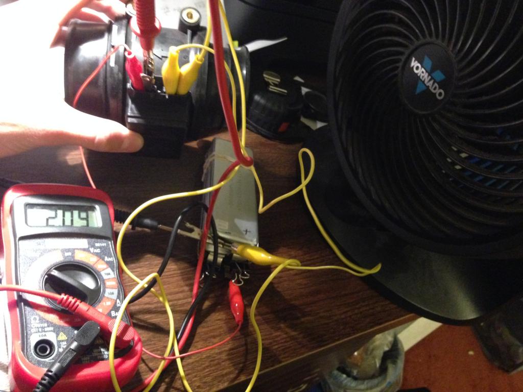
I have a household fan and am measuring voltage with it off and with it blowing full blast into the MAF. I think that should be enough airflow to get a reading on my DMM but nada
Reply
0
0
02-25-2014, 10:41 PM
#6
Senior Member
Thread Starter
iTrader: (8)
Join Date: Jan 2012
Location: Azusa, CA
Posts: 1,407
Total Cats: 116
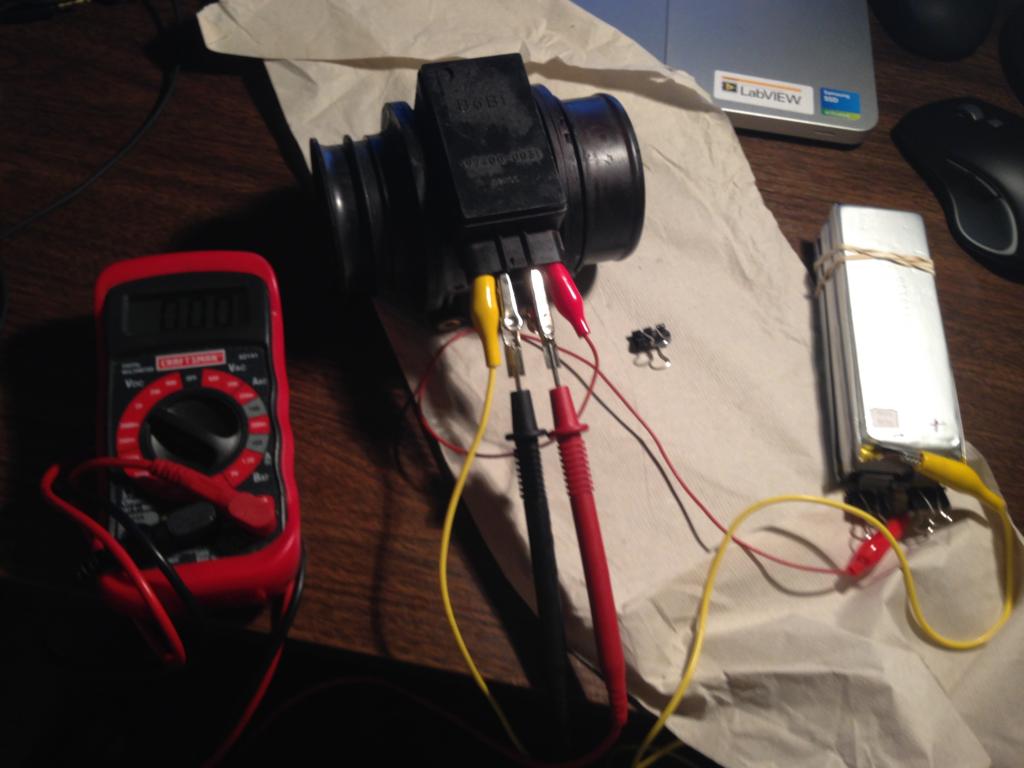
This is how I have it wired at the moment. red alligator is +11.55 from a battery and yellow is the battery negative terminal. 2nd pin from left is DMM ground and 4th from the left is DMM positive. (I made sure I have clean connections to the pin without the two adjacent alligator clips touching). Still no voltage regardless of airflow.

Reply
0
0
02-26-2014, 12:18 AM
#7
Senior Member
Thread Starter
iTrader: (8)
Join Date: Jan 2012
Location: Azusa, CA
Posts: 1,407
Total Cats: 116
This says far left is ecu ground (signal ground). but either way I still get 0 V regardless of airflow.
How to Test a 1995 Mazda Miata Mass Air Flow Sensor | eHow
Nice write up by the way Joe!
AFM Removal from the 1.6 liter Miata using eManage Ultimate
How to Test a 1995 Mazda Miata Mass Air Flow Sensor | eHow
Nice write up by the way Joe!
AFM Removal from the 1.6 liter Miata using eManage Ultimate
Reply
0
0
02-26-2014, 07:14 AM
#8
Boost Pope
iTrader: (8)
Join Date: Sep 2005
Location: Chicago. (The less-murder part.)
Posts: 33,052
Total Cats: 6,615
Just a quick note as I hop on the train- you should probably ground both MAF grounds to the same point, and take your measurement relative to that combined ground.
Reply
1
1
02-26-2014, 09:41 AM
#9
Senior Member
Thread Starter
iTrader: (8)
Join Date: Jan 2012
Location: Azusa, CA
Posts: 1,407
Total Cats: 116
Okay, so the sensor ground and power ground should both go to the negative battery terminal and use a DMM to find the voltage from common ground to the sensor output 0-5V?
Reply
0
0


Thread
Thread Starter
Forum
Replies
Last Post
Zaphod
MEGAsquirt
47
10-26-2018 11:00 PM
JesseTheNoob
DIY Turbo Discussion
15
09-30-2015 02:44 PM


